When you click on links to various merchants on this site and make a purchase, this can result in this site earning a commission. Affiliate programs and affiliations include, but are not limited to, the eBay Partner Network.
I'll include a couple of pic's here with a bit of an explanation. More detail will have to wait 'til I have a bit more time In a nutshell, there was a power supply problem.
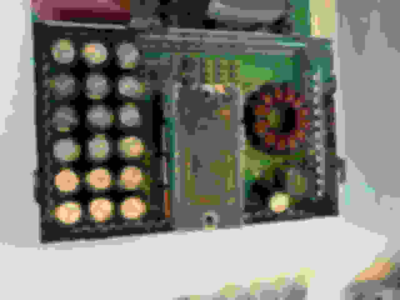
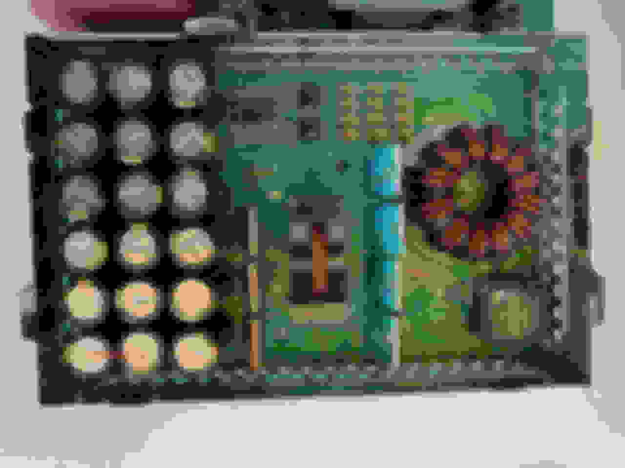
The unit is pretty straight forward to remove once you get the right side of the trunk liner out. Disassembly of the amp is also reasonable, although you do have to remove 7 screws under the "Mark Levinson" label on the top (Fig 1). There are 5 o-rings on the sides of the board that friction fit into extrusions on the inside. If took me a bit to get them going; push in from the power supply end (and out the fan end - to make it easier to disconnect the fan plugs). Fig 2 just shows how I had to pry on the end of the board to get it to start sliding out or the case.
Fig 1
Fig 2
Fig 3 and 4 show the top of the power supply end of the board with the top shield off and then the shield/heat sink removed from around the transformer. There are 2 screws that were removed from the top of the case, and 2 more that mount it to the board from the bottom.
Fig 3
Fig 4
There are also a 3.3V and 5V supply in the power supply end (which were working fine), but the main one is a DC/DC from 12V to +/- 4V for the audio section. When I first set this up on a bench, I managed to catch a 'scope trace of the -4V supply trying to start up and then aborting. I traced this to Q116 which is shown already removed in the pics above. There are 4 - IRF1404Z FETs (2 pairs of 2) driving the input side of that middle transformer from the 12V supply (filtered by 18 1000uF cap's). You can get an automotive spec'd version of those (AUIRF1404Z) which I ordered. I replaced Q116 and the 4V almost came up and then died again, so back to the drawing board to look at the output side. There are 4 dual Shottky diodes on the output end of that transformer (PN: 43CTQ100). Although I haven't figured out exactly how these are configured, they appear to be used in parallel as I later found one side of a couple of them shorted and was able to get the output going by leaving off the shorted side. Bottom line, I think it was a diode going first that took out the driver FET (did that 2 more times before I was done!). I ended up replacing all 4 diode parts and just the one FET before I got it working so it would handle a load. Fig 5 shows the bottom of the PS side of the board were you can see the bottom of the FETs and diodes (with Q116 removed).
Fig 5
Notes (in no particular order):
1) you of course need to re-mount the FETs and diodes with a thermally conductive paste (like ChipQuik)
2) all these components are also insulated from the heat sink / transformer shield, so don't damage the electrically insulating membranes so you can re-use them
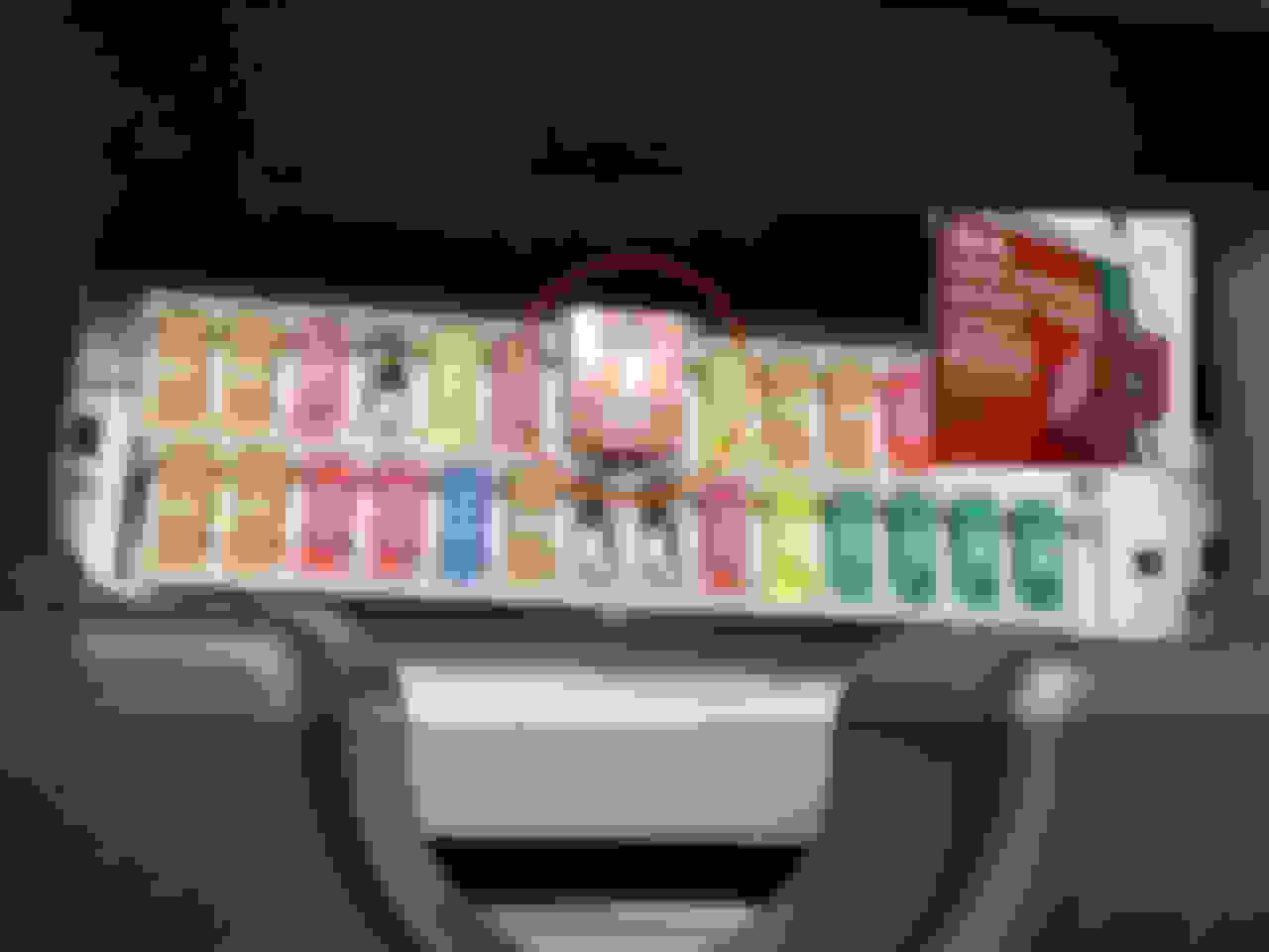
3) you can monitor the +/- 4V outputs by tapping the collectors of any complementary pairs of the bipolar output transistors in the audio section (NPN: 2N6488-> +rail; PNP: 2N6491-> -rail). Fig 6 is a 'scope trace of the supplies coming up and then shutting down when I provided an IGN/ACC input; the 12V input to the supply is always hot unless the 30A fuse in the panel under the passenger side (Fig 7) is blown - I did that too during one test .
4) I have other scope traces; one that shows the 12V input crashing as the supply tries to start and another that shows the output at the same time.
5) I used a little silicon grease on the rings so the board would slide back in easier.
6) I've seen some cite a symptom of blowing out that 30 fuse. I think it's a diode(s) that goes first. If the FETs can survive it will sit there "ticking" as it tries to start up. If it's bad enough that it takes out a FET, as it did for me during one in-car test, then it will blow the fuse and just go dead (and keep blowing that fuse).
7) after all this, the drive signal on the one FET (Q116) is still a bit "jittery" while the other 3 are solid(?). I'm a bit nervous that something else is amiss, but it's been in there about a month now and still seems to be holding up fine. I have to pull it again and stick the remaining trim on and try to re-seal the board (I had to scrape off the conformal coating to work on the board. I'm too cheap to spend the $50 to buy that stuff, so I'm going to use some brush-on electricians tape. I've done some simple tests with it and I think it will do the job Fig_6
Sokay, I am pulling mine and sending it to New Jersey. Spoke with them last week. Just have to get it out of my trunk and box it. Thanks a bunch though! Stay safe.
I have narrowed my audio issue to the wires that come from the frame of the car to the connector. When I hold the wires the apart a little about 5-7cm from the connector the audio works fine. As soon as I bolt the amp into the body of the car and the wires are tight again the audio drops. Has anyone had this issue / know a remedy?
Thanks, Thomas
I have a 2004 with the ML and Nav system. The sound has started cutting out, all channels. I moved the fader control to the front speakers and the sound is fine, left and right. If I add the read speakers, the sound starts cutting out. If you turn the volume control down is works for all channels.
If the volume is turned up past 1/4, the sound cuts out. I presume this is a power amp issue but since it works on the front channels, I am not sure. The power supply for the power amp is working I guess since there is full front L/R sound. I also guess the subwoofer is driven off of the read channels. I am also getting DVD ERROR when I insert the magazine. Not sure if these are related as the system has a communication bus that talks to all of the components.
Any guesses??
I have the exact same problem in my new to me 2005 LX 470. Did you get an answer/solution to this? Is it the amp or the rear speakers?
my speakers in my car will all shut off except for the front speakers and then i have to turn my car off then back on my RC F to get all the speakers to work again
does that mean my amp is going out?
i have amplifier marklevinson 86280-0WA40 the power startup and shutting down
Originally Posted by denardlync
I'll include a couple of pic's here with a bit of an explanation. More detail will have to wait 'til I have a bit more time In a nutshell, there was a power supply problem.
The unit is pretty straight forward to remove once you get the right side of the trunk liner out. Disassembly of the amp is also reasonable, although you do have to remove 7 screws under the "Mark Levinson" label on the top (Fig 1). There are 5 o-rings on the sides of the board that friction fit into extrusions on the inside. If took me a bit to get them going; push in from the power supply end (and out the fan end - to make it easier to disconnect the fan plugs). Fig 2 just shows how I had to pry on the end of the board to get it to start sliding out or the case.
Fig 1
Fig 2
Fig 3 and 4 show the top of the power supply end of the board with the top shield off and then the shield/heat sink removed from around the transformer. There are 2 screws that were removed from the top of the case, and 2 more that mount it to the board from the bottom.
Fig 3
Fig 4
There are also a 3.3V and 5V supply in the power supply end (which were working fine), but the main one is a DC/DC from 12V to +/- 4V for the audio section. When I first set this up on a bench, I managed to catch a 'scope trace of the -4V supply trying to start up and then aborting. I traced this to Q116 which is shown already removed in the pics above. There are 4 - IRF1404Z FETs (2 pairs of 2) driving the input side of that middle transformer from the 12V supply (filtered by 18 1000uF cap's). You can get an automotive spec'd version of those (AUIRF1404Z) which I ordered. I replaced Q116 and the 4V almost came up and then died again, so back to the drawing board to look at the output side. There are 4 dual Shottky diodes on the output end of that transformer (PN: 43CTQ100). Although I haven't figured out exactly how these are configured, they appear to be used in parallel as I later found one side of a couple of them shorted and was able to get the output going by leaving off the shorted side. Bottom line, I think it was a diode going first that took out the driver FET (did that 2 more times before I was done!). I ended up replacing all 4 diode parts and just the one FET before I got it working so it would handle a load. Fig 5 shows the bottom of the PS side of the board were you can see the bottom of the FETs and diodes (with Q116 removed).
Fig 5
Notes (in no particular order):
1) you of course need to re-mount the FETs and diodes with a thermally conductive paste (like ChipQuik)
2) all these components are also insulated from the heat sink / transformer shield, so don't damage the electrically insulating membranes so you can re-use them
3) you can monitor the +/- 4V outputs by tapping the collectors of any complementary pairs of the bipolar output transistors in the audio section (NPN: 2N6488-> +rail; PNP: 2N6491-> -rail). Fig 6 is a 'scope trace of the supplies coming up and then shutting down when I provided an IGN/ACC input; the 12V input to the supply is always hot unless the 30A fuse in the panel under the passenger side (Fig 7) is blown - I did that too during one test .
4) I have other scope traces; one that shows the 12V input crashing as the supply tries to start and another that shows the output at the same time.
5) I used a little silicon grease on the rings so the board would slide back in easier.
6) I've seen some cite a symptom of blowing out that 30 fuse. I think it's a diode(s) that goes first. If the FETs can survive it will sit there "ticking" as it tries to start up. If it's bad enough that it takes out a FET, as it did for me during one in-car test, then it will blow the fuse and just go dead (and keep blowing that fuse).
7) after all this, the drive signal on the one FET (Q116) is still a bit "jittery" while the other 3 are solid(?). I'm a bit nervous that something else is amiss, but it's been in there about a month now and still seems to be holding up fine. I have to pull it again and stick the remaining trim on and try to re-seal the board (I had to scrape off the conformal coating to work on the board. I'm too cheap to spend the $50 to buy that stuff, so I'm going to use some brush-on electricians tape. I've done some simple tests with it and I think it will do the job Fig_6
please i have amplifier marklevinson 86280-0WA40
the power starting up +/-4v and shutting down
and restart.
i check all the power unit how can to help me to get fixed .
please.
Sorry - the car I had with that amp had an accident and was written off (I know longer have it).
There are others in this thread that have listed a couple of places that will repair these; that�s the best I can suggest for now. There's may have some updated information.
- denard
Originally Posted by esmaeil
please i have amplifier marklevinson 86280-0WA40
the power starting up +/-4v and shutting down
and restart.
i check all the power unit how can to help me to get fixed .
please.
Hi
We repair all types of Levinson Amps .... I can tell you that the $250 + price-tag is well worth it.
I can also tell you that there is no $5 component that needs changed either - or not normally.
The complete circuit board is covered in an epoxy resin glue which makes working on them very difficult - this has to be removed first ...... If the DSP processor (more often than not) has to be replaced , it's a very lengthy and tricky job ..the whole area is covered in glue - the processor IC has 208 legs each the width of a hair - to do this manually by hand is pretty much an art.
The Flash ROM may also need reprogrammed after repair - make sure you have the correct one ! - could be one of many.
Also - most of the general components are that small ( 1mm pitch ) that there are no markings on them ..... so unless you know what your looking at you've no chance of checking/replacing.
Why is there so few people repairing ALL faults on them ?? most companies would give up 5 minutes after opening the box !
I'm having to deal with an ML amp failure in an '07 LS460. It started last night with a clicking noise replacing the music. I had a Lexus tech remove the fuse from the front passenger side panel. Now the whole system is silent. Is this the sign that the amp needs replacement/repair? I show a part number of 86800W480 with a replacement cost of $3800.
Is removal of the amp from the trunk rather straightforward? I'm willing to live without the system for a while but I don't want to purchase anything if I'm looking at the WRONG part to replace.
Also, replacing the system itself is another expensive proposition.
Any and all help will be appreciated.
It is your amp, easy to remove from the right side of the trunk (on the spare wheel location), once out you can replace it with a Ebay one or repair it (more $)
Did you do this mod before your amp failed? And if it had failed, would you have done the same mod to the replacement unit?
I'm trying to locate a replacement ML amp for my '07 LS.


 In a nutshell, there was a power supply problem.