When you click on links to various merchants on this site and make a purchase, this can result in this site earning a commission. Affiliate programs and affiliations include, but are not limited to, the eBay Partner Network.
Retrofit/Pixel Performance RGB LED DRL - wiring help
Hi All,
Recently bought this and am ready to install. However, I am not quite familiar with headlight wiring in cars and don't want to mess up any electrical components (Obviously)
This is the product that recently became available from the RetrofitSource https://www.theretrofitsource.com/14...rl-boards.html
Any one know how to properly wire this? As in which color wiring taps into which component of the car (turn signal, DRL, parking lights).
Installation guide not available yet from website.
**Going to post pic of the product itself once I get home**
From reading the information on the product, it appears it comes with a sub harness that has factory connections, so I assume you're not splicing into the factory harness...just plug and play.
However, it also looks like you have to open the DRL lights to install the board...which would mean the front bumper needs to come off.
It would be nice to see the actual product to understand what is involved.
i have to tap i to the OEM wiring for the switchback turn signals.
yep will upload pictures of the product soon with all the wiring (does come with harness); and yes must remove the bumper.
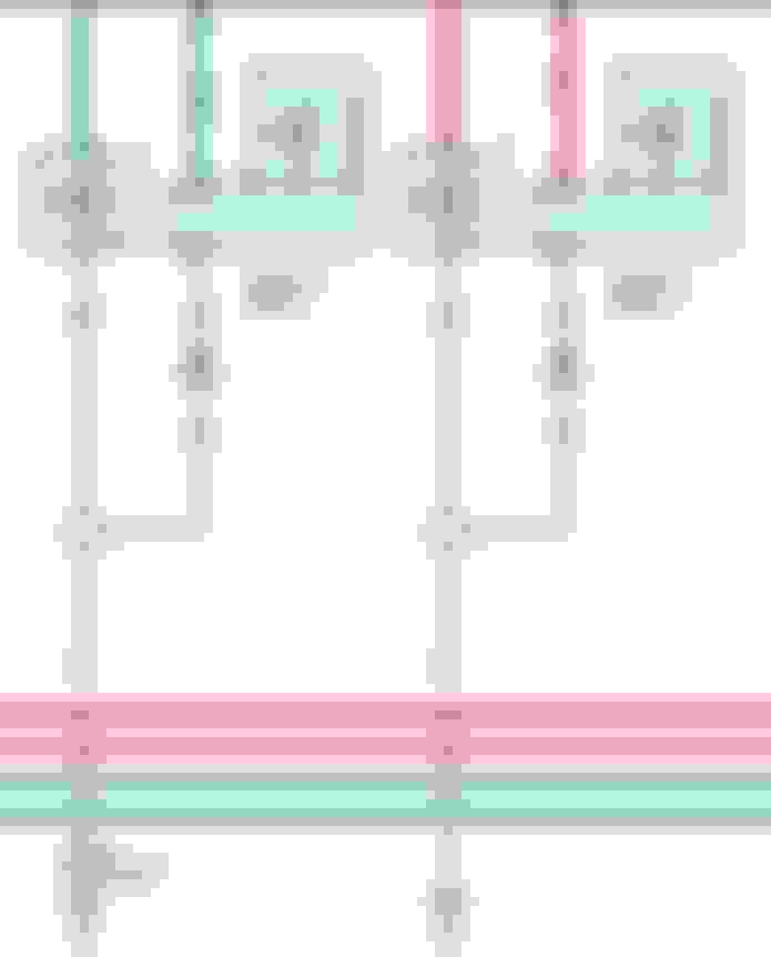
Here's the turn signal...it may not be everything you need, but once you check out the product, hopefully it identifies all the connections you need to make. Just ask for whatever you're missing.
All connectors are 5 pins
3 color coded wires from the driver of which i believe are :
- ground
- turn signal tap
- Parking light tap (for dimming when Headlights go on)
�Thanks for your email! You should have three colors there on the factory connector green, black and yellow. You will connect the red wire to the green, black to black and yellow to white. The orange wire will tap into the turn signal power wire.�
Thanks again for your help,
i�ll post up pictures of the finished product
Bought the same kit about 2 months ago. finally recieved it 2 days ago because the actual boards arent distributed anymore. The red white and black wires splice in to the old DRL wires, the yellow wire splices into the turn signal circuit. you plug the shorter end(with the do no bypass tag) into the DRL board, and the longer end plugs into the Morimoto RGB Controller. Im doing my install on saturday. Let me know how it comes out if you end up doing it before me, and how the DRL removal and cracking go. I started a nearly identical thread to this about 2 weeks ago, didnt get the info I was looking for, your thread filled in the gaps.
Bought the same kit about 2 months ago. finally recieved it 2 days ago because the actual boards arent distributed anymore. The red white and black wires splice in to the old DRL wires, the yellow wire splices into the turn signal circuit. you plug the shorter end(with the do no bypass tag) into the DRL board, and the longer end plugs into the Morimoto RGB Controller. Im doing my install on saturday. Let me know how it comes out if you end up doing it before me, and how the DRL removal and cracking go. I started a nearly identical thread to this about 2 weeks ago, didnt get the info I was looking for, your thread filled in the gaps.
Started take the DRL apart, it was quite easy.
Now, I was wondering if you ended up taking off the old DRL or you simply 3m'ed the new board to the old one?
Seems like a hassle to ply off all the little caps and rip off the old board.
Putting the car on jack stands later, then driving the rims off to the powder coat shop. once that�s done i�m taking the bumper off and doing the DRL�s. I�ll let you know what i do
Please please show pics when you're finished, especially with just the standard light color on. Does it update the DRLs so that it's more a solid LED instead of the dotted ones from OEM? I was very curious in this product from TRS but couldn't find any pictures.