When you click on links to various merchants on this site and make a purchase, this can result in this site earning a commission. Affiliate programs and affiliations include, but are not limited to, the eBay Partner Network.
A good source is local sign companies. They usually have a water-jet cutter in house and lots of various material, even scrap for cheap sometimes (Metals, Plastics, etc). They probably won't have CF but they might be able to source it. Otherwise just look on eBay and try and find a flat sheet of 2mm thick CF large enough to cut a cover from and bring it to them to cut.
Reminds me of my crude version of that I ran for several years. Eventually I really missed having the cigarette lighter for charging my phone. I thought I heard he was ending his business venture and was doing one final closeout sale before he closes up shop.
I was just in contact with the guy who founded and runs AutoExtrude a couple of days before reading your post. I was following up with him today about a custom order request I've made and relayed my concern about his possibly closing up shop soon. He told me that is not the case at all.
This was his response:
"...if you want to throw down a comment for me and let people know that I am not gone. I was going to close up shop but decided not to. I kept it open, doubled down on product development, hired a general manager and made a website... Feel free to let them know I’ll be doing more for the SC300/400 and GS300/400."
You can find his company on Facebook. I've forwarded him the link to this thread so that he and/or his general manager can respond themselves if they wish to.
Hello guys, my name is Jonathan. The owner of AutoExtrude. I read your entire thread and you guys have been doing some really great stuff here. I always like to see a technological progression in our cars name. I wish I could contribute in an open-source methodology like all of you guys but I have a different doctrine on that front. I have a couple free ideas I can put out to the community when I get around to it, I'll be sure to share on here. Thank you...
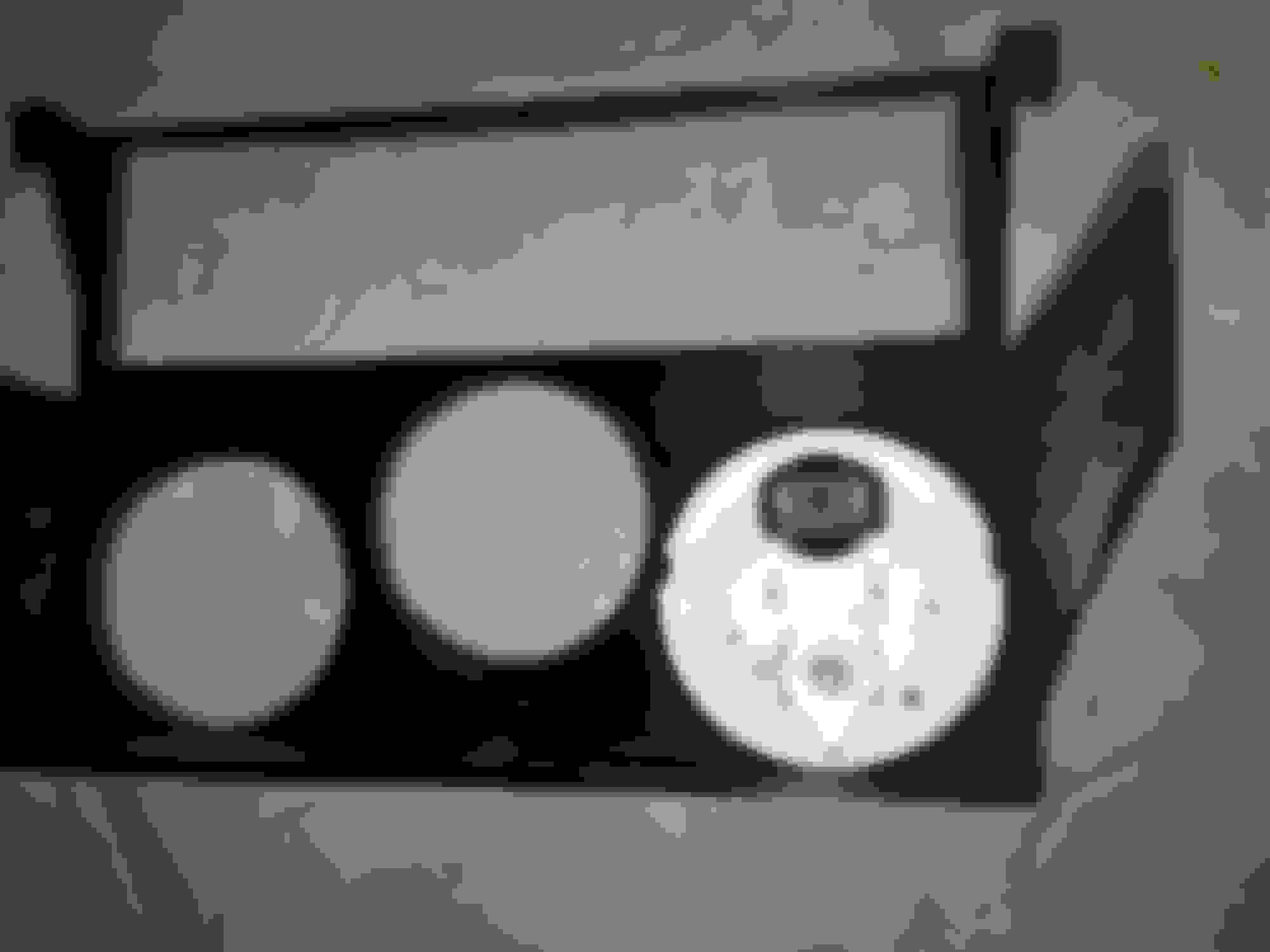
A small update on implementing the beautiful triple gauge bezel that MLeopard designed. As my engine swap project is moving along I've returned to this since I need to run the wiring for the various gauge senders soon. I have a VDO/Continental radio and VDO Vision Black Voltmeter and 0-150 PSI oil pressure gauges on order but I picked up a third VDO Vision Black transmission pressure gauge a little quicker from Amazon which came in yesterday.
I was excited to do a quick test fit with the spin-lock on the inside of the 3D printed bezel but I ran into an issue, at least when using these VDO gauges. MLeopard, your initial concern with this was correct. While the VDO gauges themselves could be spaced out just enough to fit in place, there are clearance issues when using the rear spin-on lock cylinders to set them into place.
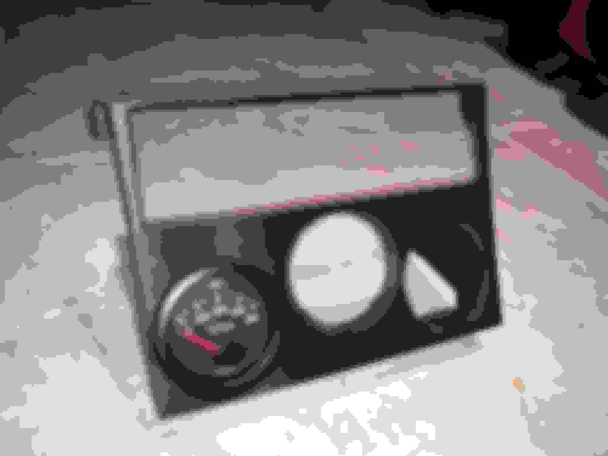
The center gauge fits and locks in perfectly but the other two on the right and left only fit in loose without their respective locking cylinders. The VDO schematics with dimensions probably did not cover the dimensions of the rear spin-locks.
I can see that there isn't much room for readjustment in the CAD file. I can Dremel tool to trim out most or all of the sides and bottom of the assembly where the spin locks are hitting but this would probably start to compromise the structural integrity and flex resistance of the assembly.
If more millimeters of room are needed internally on the sides and at the bottom as well as between the 52mm VDO gauges themselves... I think maybe these gauges in a triple arrangement might not work vs the two gauge setup in the same bunch of CAD files or the smaller diameter triple gauge opening versions. It is SO close though! I still love the look of this bezel, MLeopard but I think you were right at the onset about the tight space for more than two 52mm gauges.
Unfortunately Egauges is taking quite a while to fulfill my order which includes the 1-DIN stereo. I really want to see how the top head unit bezel works out. Hopefully soon.
A small update on implementing the beautiful triple gauge bezel that MLeopard designed. As my engine swap project is moving along I've returned to this since I need to run the wiring for the various gauge senders soon. I have a VDO/Continental radio and VDO Vision Black Voltmeter and 0-150 PSI oil pressure gauges on order but I picked up a third VDO Vision Black transmission pressure gauge a little quicker from Amazon which came in yesterday.
I was excited to do a quick test fit with the spin-lock on the inside of the 3D printed bezel but I ran into an issue, at least when using these VDO gauges. MLeopard, your initial concern with this was correct. While the VDO gauges themselves could be spaced out just enough to fit in place, there are clearance issues when using the rear spin-on lock cylinders to set them into place.
The center gauge fits and locks in perfectly but the other two on the right and left only fit in loose without their respective locking cylinders. The VDO schematics with dimensions probably did not cover the dimensions of the rear spin-locks.
I can see that there isn't much room for readjustment in the CAD file. I can Dremel tool to trim out most or all of the sides and bottom of the assembly where the spin locks are hitting but this would probably start to compromise the structural integrity and flex resistance of the assembly.
If more millimeters of room are needed internally on the sides and at the bottom as well as between the 52mm VDO gauges themselves... I think maybe these gauges in a triple arrangement might not work vs the two gauge setup in the same bunch of CAD files or the smaller diameter triple gauge opening versions. It is SO close though! I still love the look of this bezel, MLeopard but I think you were right at the onset about the tight space for more than two 52mm gauges.
Unfortunately Egauges is taking quite a while to fulfill my order which includes the 1-DIN stereo. I really want to see how the top head unit bezel works out. Hopefully soon.
I went back and looked at VDO's tech sheets and I see that I made a couple of errors with the lock ring reliefs. I made them the exact same diameter as what the lock rings should be. I should have put some clearance in there.I also see that I neglected to relief cut the brace I added along the bottom.
What is the actual diameter of the lock ring?
It's possible that you can forgo the lock rings and perhaps use some tape wrapped around the gauges to hold them in their holes. I employed that tactic in the A pillar gauge mount I have on my Firebird. I hope you can find a solution!
Hello guys, my name is Jonathan. The owner of AutoExtrude. I read your entire thread and you guys have been doing some really great stuff here. I always like to see a technological progression in our cars name. I wish I could contribute in an open-source methodology like all of you guys but I have a different doctrine on that front. I have a couple free ideas I can put out to the community when I get around to it, I'll be sure to share on here. Thank you...
Would love to see what you do feel you can share. I'm curious what your parts are printed from?
I went back and looked at VDO's tech sheets and I see that I made a couple of errors with the lock ring reliefs. I made them the exact same diameter as what the lock rings should be. I should have put some clearance in there.I also see that I neglected to relief cut the brace I added along the bottom.
What is the actual diameter of the lock ring?
It's possible that you can forgo the lock rings and perhaps use some tape wrapped around the gauges to hold them in their holes. I employed that tactic in the A pillar gauge mount I have on my Firebird. I hope you can find a solution!
I used the tape method to hold my gauges also. Works really well.
I’d prefer not to use tape to hold my gauges in if I can find any other solution. There has to be something I can do to massage the 3D printed housing just a bit with my Dremel, though that won’t help the lock rings being spaced from each other if they conflict.
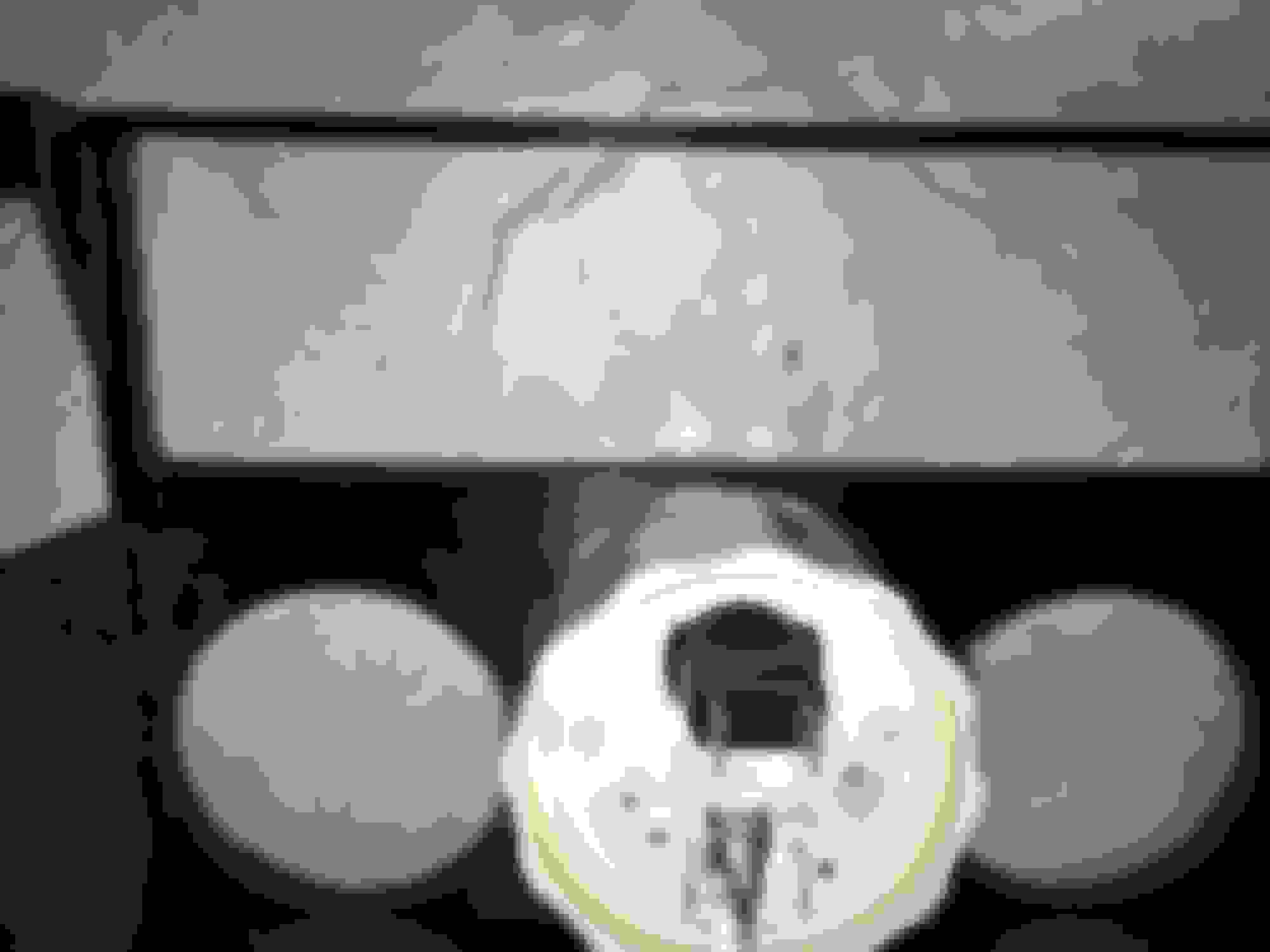
Edit: I just cleaned up the gauge holes with my Dremel and examined the spin-lock ring clearances in the rear again. In the rear I'd have to cut away all of the lower structural support material immediately below the far left and far right gauges and a significant portion of the mounting structures on each side of the bezel assembly. I don't think the bezel would be nearly as sturdy after having done those cutaways.
Further, while from the back it looks like the far left and far right gauges could be moved upward in a revised CAD file, at the front there is almost no more room to work with to do this without losing the structural integrity between each hole's separation from the one closest to it. Even if not it might be a challenge for a 3D printer to make such fine separations in a clean way. I'm willing to bet that there are a very few more millimeters to work with if there were a revision but it would still be a very tight situation.
I now have a MUCH better appreciation for what you were up against, MLeopard.
According to my caliper gauge the diameter of the VDO spin-lock rings comes to 64mm each.
I�d prefer not to use tape to hold my gauges in if I can find any other solution. There has to be something I can do to massage the 3D printed housing just a bit with my Dremel, though that won�t help the lock rings being spaced from each other if they conflict.
Edit: I just cleaned up the gauge holes with my Dremel and examined the spin-lock ring clearances in the rear again. In the rear I'd have to cut away all of the lower structural support material immediately below the far left and far right gauges and a significant portion of the mounting structures on each side of the bezel assembly. I don't think the bezel would be nearly as sturdy after having done those cutaways.
Further, while from the back it looks like the far left and far right gauges could be moved upward in a revised CAD file, at the front there is almost no more room to work with to do this without losing the structural integrity between each hole's separation from the one closest to it. Even if not it might be a challenge for a 3D printer to make such fine separations in a clean way. I'm willing to bet that there are a very few more millimeters to work with if there were a revision but it would still be a very tight situation.
I now have a MUCH better appreciation for what you were up against, MLeopard.
According to my caliper gauge the diameter of the VDO spin-lock rings comes to 64mm each.
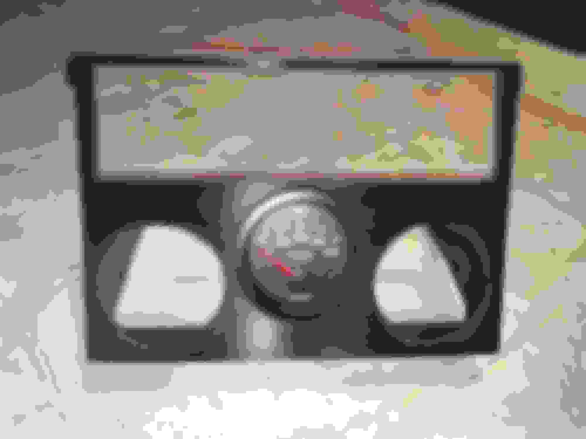
Yes it is a very tight fit. I wouldn't have even gotten your hopes up if VDO's tech sheet was right. They show the diameter of the lock ring as 59mm. At least the way I read it. As you're observing 64 is just too big.
Yes it is a very tight fit. I wouldn't have even gotten your hopes up if VDO's tech sheet was right. They show the diameter of the lock ring as 59mm. At least the way I read it. As you're observing 64 is just too big.
Aw darn it :/ Thanks for the inaccurate information, VDO. MLeopard, thank you very much for creating the design nonetheless. I still think it's a great variant of your first designs. Actually maybe the answer is to incorporate a smaller diameter gauge or... something... in the middle while the two side gauges are moved in and up a bit. Still mostly triangular configuration but just no longer incorporating a matched set of three gauges any longer.
But then... this skirts closer to your original two gauge design and its angled LHD & RHD variants. Begs the question of what other significant thing could that space be used for that is a decent size smaller in diameter than 52mm front and 64mm rear?
Still, using another brand's 52mm gauge with this three gauge bezel design might bear fruit if a much simpler and thinner rear affixing method were designed into the gauge but this sadly rules out the VDO Vision Black series for this three gauge bezel.
Does anyone have CAD files of the Lexus SC300 dash? I'm trying to model a gauge pod setup like the one below:
However, I want to mold the bottom of my gauge pod to the dash, that way we can have better fitment. See below for prototype CAD of the gauge pod.
Wow that looks pretty good actually. I think you may have to take measurements and do some test fits as I havent heard of that one before.
Halon, have you made a vvti Ge spark plug cover?
I have been saving the non vvti plug cover, and tried with a non vvti exhaust cover and vvti intake cover, but the oil cap cutout is off and the intake cover only has one bolt hole.
Can I send you some measurementls? Lol.
Nah i haven't. It doesn't have any spots for fasteners in the rear, and the fronts had super tall studs or something from what i remember. Just seemed like it wasnt going to work out as nicely so i skipped it.
There is one bolt hole that is like the non vvti one on the intake side, the second one from the front so that is already good.
I will just try and make something using that one hole for supporting the intake side.
The oil cutout gets moved to basically where the first bolt would have been.
For the rear, the intake side line can move in some to delete the rear holes and that would clear the narrower cover.
The super tall studs don't have to stay.
You are right it probably wouldn't work at all if i was using a vvti exhaust cover, but since I can use the non-vvti exhaust cover, it might just be stable enough to not flap around too much.
apparently I can't use the solidworks trail as i just tried, so I downloaded the freeCAD and opened the GE spark plug cover.
It all shows up fine except I can't see the curved line for the oil cap and the curved line at the front, is that normal?
pic so you can see what I mean. And I do really need to clean and paint the covers

 04-04-18, 09:02 AM