When you click on links to various merchants on this site and make a purchase, this can result in this site earning a commission. Affiliate programs and affiliations include, but are not limited to, the eBay Partner Network.
I have a problem no one has shown yet I thought I had the clip released and I pulled the plug off the wires.
anyone have a wireing schematic? I have no idea how to get to the wires to re attach the plug?
I was so close and would have been done with the job now if it had disconnected.
My thought would be to find the path of the wires and find the next plug and then run a separate wire strand to where the plug is missing now. ( I now think I wont have the opportunity to splice in a jumper )
run a different set of wires to the plug location and then connect the o2 sensor.
After looking at the wiring scheme it does not look that easy to find access to tie in a new set of wires.
I am now thinking of soldering in wires to the exposed wires and adding some length to the cable before the restored plug. then plugging the new O2 sensor in. I will use the old plug wires as my extension wires.
I will spend some time tomorrow and get this resolved.
I cannot really tell which plug it is you're showing in the picture. If you're asking about the O2 sensor plug that connects to the sensor...
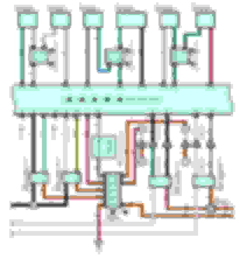
There are four O2 sensors for the LS430: "Bank1, Sensor 1"; "Bank1, Sensor 2"; "Bank2, Sensor 1"; and "Bank2, Sensor 2"... Here's the wiring schematic showing wire colors for the 4 terminals for each connector.
Here are the terminal numbers for each connector, and their part numbers...
I have pulled wires through. I have used an old O2 wires. Here is my issue I have two black wires and a white and a blue. I have one black wire to the brown on the car and one to black.
since I have them loose I don't know which black wire is connected to which. will it matter if I hook black to black to the o2 sensor? I have two black wires on the o2 sensor.
I am putting this comment to help me with the wiring
Okay then this wiring harness is 01. The white wire on the engine wiring harness is the B+ or 12 V input to the heater circuit of the sensor. It goes to either one of the heater wires on the sensor. The blue wire with a yellow tracer/line is the wire going to the other heater wire on the sensor. This is the return wire to the computer to turn the heater on. The Brown wire is the ground wire and would go to your gray wire which is the ground wire on the sensor. The black wire is the OX1 voltage input to the engine control computer and would go to the corresponding wire on your sensor. That should do it.
According to the repair manual, you should have one Blue/Yellow wire, two Black wires, and one Brown wire from the Engine Control Module. For the O2 sensor, you should have 2 Black wires, one Blue wire, and one White wire. Please confirm.
The manual shows that the wires should be connected as follow:
Terminal 1: Blue/Yellow (HTL) - connect to one of the 2 Black wires on the sensor
Terminal 2: Black (+B) - connect to the other Black wires on the sensor
Terminal 3: Black (OX2) - connect to the Blue wires on the sensor
Terminal 4: Brown (E1) - connect to the White wires on the sensor
According to the repair manual, you should have one Blue/Yellow wire, two Black wires, and one Brown wire from the Engine Control Module. For the O2 sensor, you should have 2 Black wires, one Blue wire, and one White wire. Please confirm. Yes
The manual shows that the wires should be connected as follow:
Terminal 1: Blue/Yellow (HTL) - connect to one of the 2 Black wires on the sensor Blue wire
Terminal 2: Black (+B) - connect to the other Black wires on the sensor White Wire
Terminal 3: Black (OX2) - connect to the Blue wires on the sensor Black
Terminal 4: Brown (E1) - connect to the White wires on the sensor
Black
So I will go out and test these wires above as listed for volts and Ohms. my black wires are putting out 7.94 volts when ignition turned on.
I don't know what I did but the reading on the black wires ( blue and white) was OL. terminal 2 and 1 connected = OL no reading on OHMS?
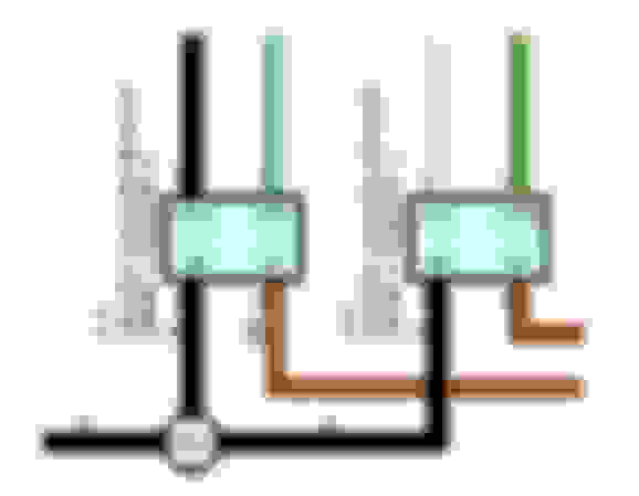
Another important thing you have to decipher is which of the 2 Black wires, from the ECM, is (+B) and which is the (OX2). Refer to the diagram below...
The (+B) Black wires for both "Bank1, Sensor1" and "Bank2, Sensor1" are tied together at "E12". Using the multimeter, you can test the 2 Black wires "Bank1, Sensor1" against the sole Black wire on "Bank2, Sensor1". Whichever one on "Bank1, Sensor1" is shorted together with the sole Black wire on "Bank2, Sensor1" is the one you should labeled (+B). The other Black wire on "Bank1, Sensor1" should be labeled (OX2).
I was thinking just to test the connections I could use the old sensor it was working before granted putting out bad readings. I will wire that up and see how the sensor likes it.
I will run a scan and see if the car bank one system is back in action.
Back in a second.
The black wires still have 7.85 volts fluctuating, I pulled codes and the bank two is putting out readings the bank 1 not.