
RX330 Front Wheel Bearings - DIY Step by Step

Thread Starter
Lead Lap
Joined: Mar 2011
Posts: 537
Likes: 83
From: Texas
Hey fellas, in this thread you will find a step by step with photos of how to do a wheel bearing replacement on an RX330. It is a labor intense job and will require that you have access to a shop press, hub shark, or can take your knuckle and new bearing to a shop and have it pressed in and out for you.
Please know that you can likely do the job in a slightly different order than the steps I did at some points, but I will walk through the way i did them.
Step one: Remove Tire and jack up car and place on stands (or lift if you have one). Note: Loosen Lug Bolts before jacking up.

Step 2: Loosen the Caliper Bolts which attach to the steering Knuckle. Use 17mm socket and long ratchet if you have one as these will be tight. They are located behind the rotor and caliper assembly on the back side of the knuckle.
Please know that you can likely do the job in a slightly different order than the steps I did at some points, but I will walk through the way i did them.
Step one: Remove Tire and jack up car and place on stands (or lift if you have one). Note: Loosen Lug Bolts before jacking up.
Step 2: Loosen the Caliper Bolts which attach to the steering Knuckle. Use 17mm socket and long ratchet if you have one as these will be tight. They are located behind the rotor and caliper assembly on the back side of the knuckle.
Last edited by HtownBlue; Jun 3, 2011 at 11:42 PM.
Thread Starter
Lead Lap
Joined: Mar 2011
Posts: 537
Likes: 83
From: Texas
Step 3: Remove entire caliper assembly with pads and all. Note: This may take a flat head screw driver to pry the assembly off the rotor. Once you remove the assembly, rest it temporarily on top of rotor.

Step 4: Tie Caliper assembly up or use bunjees to secure caliper assembly so it is not hanging by brake line.

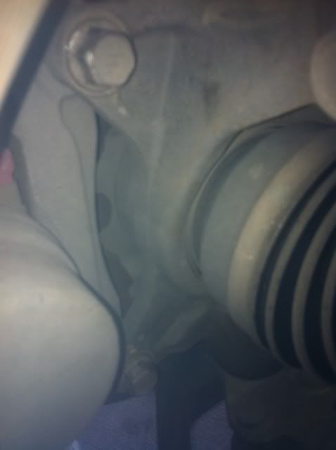
Step 5: Remove Rotor. Note: Rotor may be a bit stubborn to come off. Use hammer ON HUB, repeat ON HUB BETWEEN STUDS to help loosen rotor so it will come off. Pic shown is with it loosened and ready to be taken off hub.

Now should look like:

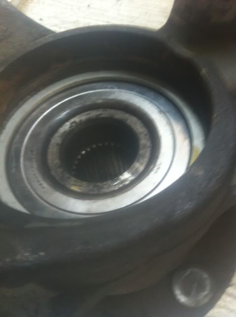
Step 6: Locate Axel Nut. This is in the interior of the Hub and looks like a twelve pointed bolt. See pic.

Step 4: Tie Caliper assembly up or use bunjees to secure caliper assembly so it is not hanging by brake line.
Step 5: Remove Rotor. Note: Rotor may be a bit stubborn to come off. Use hammer ON HUB, repeat ON HUB BETWEEN STUDS to help loosen rotor so it will come off. Pic shown is with it loosened and ready to be taken off hub.
Now should look like:
Step 6: Locate Axel Nut. This is in the interior of the Hub and looks like a twelve pointed bolt. See pic.
Thread Starter
Lead Lap
Joined: Mar 2011
Posts: 537
Likes: 83
From: Texas
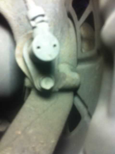
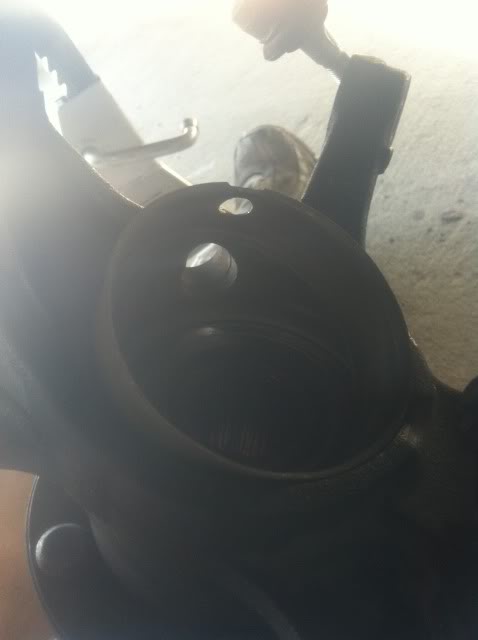
STEP 7 / 8: This is where you will need to "free" the stop on the axel nut to allow it to be taken off. Note: In the pic you will notice I positioned the axel and nut to where the "stop indention" (i do not know the tech term) is facing upwards. See photo. I did this by jacking up the other side to where the tire was off the ground and rotated the axel around to where the stop indention was facing upwards.
Locate the stop indention:

Step 8 - Bending the stop indention so as to allow the axel bolt to rotate and come free. NOTE: I did not photograph this but I will describe what I used to do this.
I used a small hard punch which fit just between slot and stop indention and hammered the punch in the space. This in turn bent the indention upwards and this enable the nut to be freed. You will have to figure out a way to get that bend, bent upwards to free the axel nut. It is not easy and you may have issues. You may try a smaller phillips head, or flat head. Sorry for no pics, but I simply hammered my punch in the "gap" and bent the "bend" the opposite way. MAKE SURE you have cleared the threads.
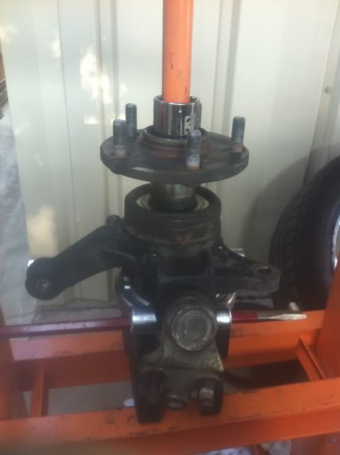
Step 9: Loosen the Axel Nut. Note: If you jacked up the other side to move the axel nut in position to free the bend, than let the other side down now. I am assuming you are not using an impact wrench in that scenario.
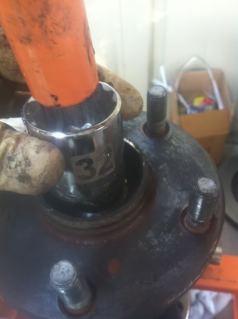
YOU MUST USE a 30 MM DEEP socket. Fit the socket on the Axel Nut securely. I used a very long breaker bar FYI. It is 24 inches. I also sprayed a little PB Blaster on the Axel threads to lubricate them as they were rusted.

Now before you torque down and loosen the axel nut, MAKE SURE you have the "stop Bend" cleared of threads or YOU WILL TEAR THE AXEL THREADS UP when removing the axel nut.
Step 10: Use them muscles boys! Take that axel nut off! Make sure the axel cannot turn. Left Loosey! Once broken loose, you should be able to attach a rachet and take it all off.

Step 11:Get a sweet smoothie, because this is about to get sour.
Step 12a: Remove the tie rod end: Notice in first photo the castle nut. Remove the cotter pin that runs through it. Use a needle nose pliers to do this. bend it straight and push through castle nut. See 1st photo for castle nut pic.
Step 12b: Remove tie rod from steering knuckle.
I have a wonderful tool for this in the pic. However you can use a tie rod end fork and hammer it in to separate it. If you are desperate, use and OLD nut that fits properly and use hammer on nut to free tie rod end from knuckle. I recommend getting a tool for it though. See photo for my tool.


Locate the stop indention:
Step 8 - Bending the stop indention so as to allow the axel bolt to rotate and come free. NOTE: I did not photograph this but I will describe what I used to do this.
I used a small hard punch which fit just between slot and stop indention and hammered the punch in the space. This in turn bent the indention upwards and this enable the nut to be freed. You will have to figure out a way to get that bend, bent upwards to free the axel nut. It is not easy and you may have issues. You may try a smaller phillips head, or flat head. Sorry for no pics, but I simply hammered my punch in the "gap" and bent the "bend" the opposite way. MAKE SURE you have cleared the threads.
Step 9: Loosen the Axel Nut. Note: If you jacked up the other side to move the axel nut in position to free the bend, than let the other side down now. I am assuming you are not using an impact wrench in that scenario.
YOU MUST USE a 30 MM DEEP socket. Fit the socket on the Axel Nut securely. I used a very long breaker bar FYI. It is 24 inches. I also sprayed a little PB Blaster on the Axel threads to lubricate them as they were rusted.
Now before you torque down and loosen the axel nut, MAKE SURE you have the "stop Bend" cleared of threads or YOU WILL TEAR THE AXEL THREADS UP when removing the axel nut.
Step 10: Use them muscles boys! Take that axel nut off! Make sure the axel cannot turn. Left Loosey! Once broken loose, you should be able to attach a rachet and take it all off.
Step 11:Get a sweet smoothie, because this is about to get sour.
Step 12a: Remove the tie rod end: Notice in first photo the castle nut. Remove the cotter pin that runs through it. Use a needle nose pliers to do this. bend it straight and push through castle nut. See 1st photo for castle nut pic.
Step 12b: Remove tie rod from steering knuckle.
I have a wonderful tool for this in the pic. However you can use a tie rod end fork and hammer it in to separate it. If you are desperate, use and OLD nut that fits properly and use hammer on nut to free tie rod end from knuckle. I recommend getting a tool for it though. See photo for my tool.
Thread Starter
Lead Lap
Joined: Mar 2011
Posts: 537
Likes: 83
From: Texas
See photo of removed tie rod end.

Step 13: Remove speed / abs sensor. Use 10 MM socket or wrench. This is located on back side of hub, just below where the Strut cross bolts conneect with the knuckle. Loosen this and remove. Note clip that secures line to knuckle. gently remove this as well.
Speed sensor bolt:
Clip -

Step 14: Remove Strut Cross Bolts that thread through Knuckle. These are 22MM Bolt and NUT. BREAK FREE / LOOSEN NUT, NOT BOLT SIDE. NOTE: Guys, I am 200 pounds of lean muscle and the following process will take a ton of elbow grease. It is VERY difficult to break these nuts free if they have never been before. USE A LARGE CHEATER BAR. Standard size ratchet will NOT do. This requires strength.
That said, attach a SIX POINT socket to bolt and 22MM wrench / socket to bolt. Break The upper and lower nuts free. See photos. NOTE THAT I DID NOT SHOW BREAKER BAR ON NUT JUST WRENCH.
USE THEM MUSCLES BOYS!
Removed:

Step 15: Free strut from knuckle. Pry the hub assembly from strut. Note: We will remove lower ball joint from strut next, but not yet.

Step 16: No photo - Hammer end of AXEL shaft to LOOSEN through Hub. You will not remove the axel from hub yet, but you need to loosen it before removing the Ball Joint.
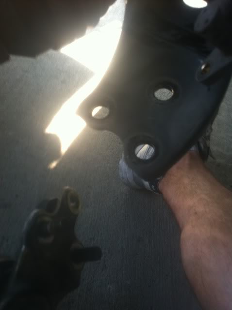
Step 17: Remove Ball Joint From steering knuckle. 3 17MM nuts / bolt. See photo.

I removed the nuts and bolt and the entire hub will be loosened now.
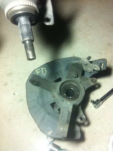
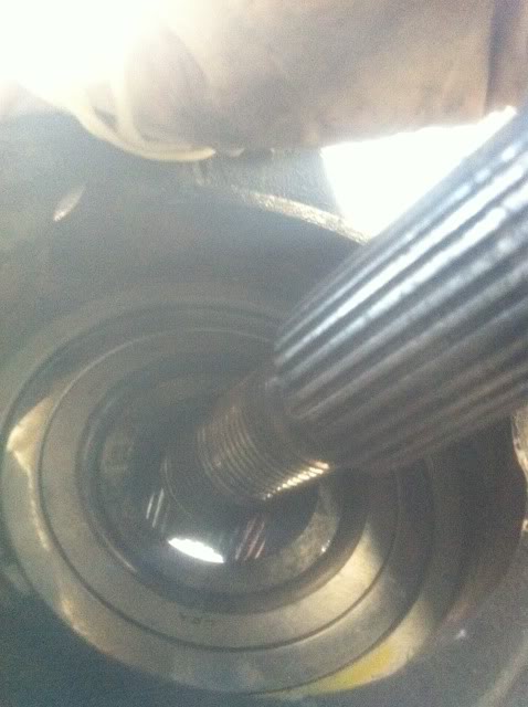
Step 18: Remove Axel shaft from hub: Slide out axel from Hub. This will leave the entire hub.knuckle and dust sheild assembly free from vehicle. See photo:
Step 13: Remove speed / abs sensor. Use 10 MM socket or wrench. This is located on back side of hub, just below where the Strut cross bolts conneect with the knuckle. Loosen this and remove. Note clip that secures line to knuckle. gently remove this as well.
Speed sensor bolt:
Clip -
Step 14: Remove Strut Cross Bolts that thread through Knuckle. These are 22MM Bolt and NUT. BREAK FREE / LOOSEN NUT, NOT BOLT SIDE. NOTE: Guys, I am 200 pounds of lean muscle and the following process will take a ton of elbow grease. It is VERY difficult to break these nuts free if they have never been before. USE A LARGE CHEATER BAR. Standard size ratchet will NOT do. This requires strength.
That said, attach a SIX POINT socket to bolt and 22MM wrench / socket to bolt. Break The upper and lower nuts free. See photos. NOTE THAT I DID NOT SHOW BREAKER BAR ON NUT JUST WRENCH.
USE THEM MUSCLES BOYS!
Removed:
Step 15: Free strut from knuckle. Pry the hub assembly from strut. Note: We will remove lower ball joint from strut next, but not yet.
Step 16: No photo - Hammer end of AXEL shaft to LOOSEN through Hub. You will not remove the axel from hub yet, but you need to loosen it before removing the Ball Joint.
Step 17: Remove Ball Joint From steering knuckle. 3 17MM nuts / bolt. See photo.
I removed the nuts and bolt and the entire hub will be loosened now.
Step 18: Remove Axel shaft from hub: Slide out axel from Hub. This will leave the entire hub.knuckle and dust sheild assembly free from vehicle. See photo:
Thread Starter
Lead Lap
Joined: Mar 2011
Posts: 537
Likes: 83
From: Texas
Step 19: Remove dust shield from Bearing area. See photos. I used a flat head to pry it loose, then used needle nose pliers to pull it loose. It is only a dust shield and may get a little bent coming out , but no worries. You can bend it back in later.

removed:

Step 20: Remove stop ring / clip. YOU MUST REMOVE THIS TO GET BEARING OUT. Use a pair of needle nose pliers to squueze on notches and remove slowly. See photo.

OK, now you are ready for the fun part. Removing the bearing / hub. If you are smart, and not dumb like me, you will pay a shop to remove the hub and bearing, and place the new bearing in and press the hub in.
I'll say this: Getting it to go in is always easier, than pulling the thing out! HAHAHAAHAHAHAHA, yeah I made a cheesey joke, so hate me.
You will need access to a press.
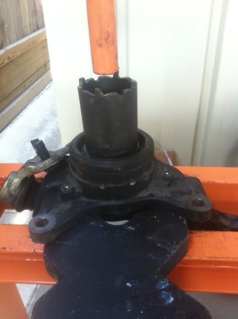
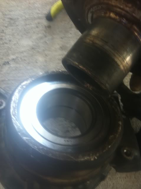
Now I will post more pics soon, but you will need a large BEARING SEPARATOR to begin the HUB removal process. The one I have is not big enough, so I will post the next steps when I find one large enough. You will need one because the knuckle is oddly shaped and will not rest level on press plates without the separators acting as a "cradle" for the knuckle while it presses down on the hub.
See the photo to describe what I mean:
I used some heavy duty extensions along with my separator halves to cradle the hub and press the hub out in the photo below.

Will post more soon..... but if you take it to get done from here, you reverse the steps once the new bearing is in.
removed:
Step 20: Remove stop ring / clip. YOU MUST REMOVE THIS TO GET BEARING OUT. Use a pair of needle nose pliers to squueze on notches and remove slowly. See photo.
OK, now you are ready for the fun part. Removing the bearing / hub. If you are smart, and not dumb like me, you will pay a shop to remove the hub and bearing, and place the new bearing in and press the hub in.
I'll say this: Getting it to go in is always easier, than pulling the thing out! HAHAHAAHAHAHAHA, yeah I made a cheesey joke, so hate me.
You will need access to a press.
Now I will post more pics soon, but you will need a large BEARING SEPARATOR to begin the HUB removal process. The one I have is not big enough, so I will post the next steps when I find one large enough. You will need one because the knuckle is oddly shaped and will not rest level on press plates without the separators acting as a "cradle" for the knuckle while it presses down on the hub.
See the photo to describe what I mean:
I used some heavy duty extensions along with my separator halves to cradle the hub and press the hub out in the photo below.
Will post more soon..... but if you take it to get done from here, you reverse the steps once the new bearing is in.
Thread Starter
Lead Lap
Joined: Mar 2011
Posts: 537
Likes: 83
From: Texas
See above photo. I used a socket that just went around edge of hub to press it out. Notice the Separator halves I used to cradle the knuckle to make it suitable to press.
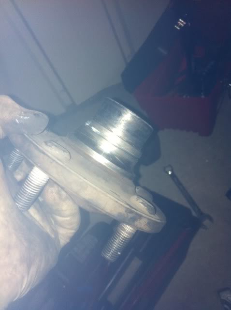
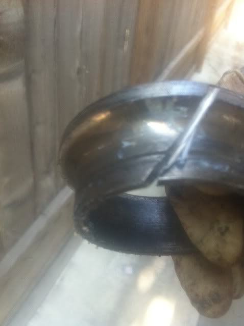
Step 23 - Remove last part of Bearing from hub. If you notice in the below photo, you will see that a part of the bearing remained on the hub. There are a few ways to get this off. I attempted to use separator halves to pry the remaining part of the bearing off the hub with no luck. So, in the pic below you will see where I used a cutting wheel to cut into the bearing. You do not need to cut through the entire thing, and be careful not to cut into hub. Simply cut about half way or so and used a flat head to pry in the cut area. This will cause the bearing to break and loosen to slide off.
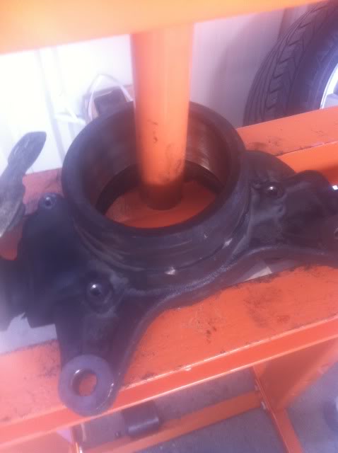
Step 24: Press remaining bearing out of knuckle assembly. To do this, you may need to use the part of the bearing that you removed from the hub. Simply place it back on top of the ball bearings. Then place a LARGE LARGE socket or bearing ring which =should cover nearly the entire bearing. make sure you are pressing the correct direction. See photo.
I pressed this very hard and then it will eventually give and slide its way out. Takes nearly 12 tons, or so.
See blank Knuckle:
Step 25: CELEBRATE!!! The hard part is done!
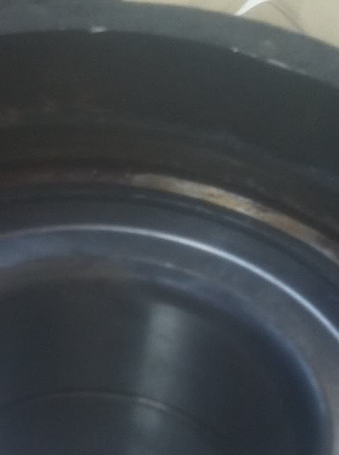
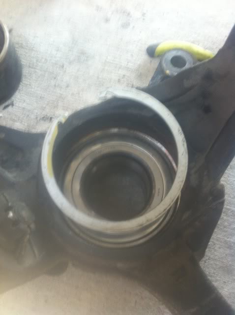
Step 26: Press new bearing in. Notice that the knuckle is facing the opposite way as the press out. You will press the bearing in ALL THE WAY until the lip catches it. You can use the same socket or bearing ring you used to press it out, to press it in. Just be careful that the bearing does not bind going in. It should slide fairly easy in.
See below photos:
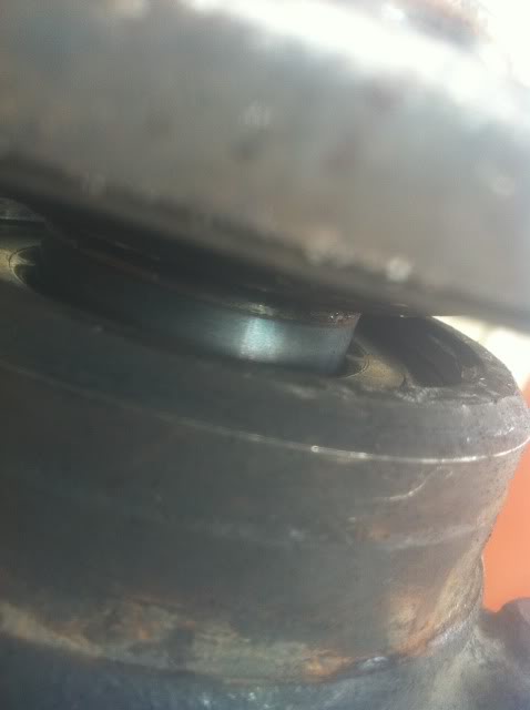
Notice the ring lip is above the bearing when it is completely pressed in. You should notice the color change.
Step 27: Place keeper ring back in (see earlier step and do in reverse).
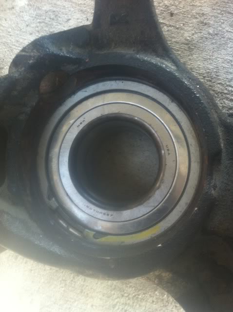
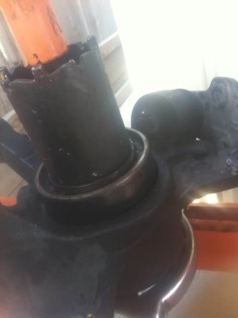
Step 28: Press Hub back into bearing / knuckle assembly. See photos. Note I used my metal plates, and separator to cradle the knuckle. I used a large socket on the hub side to help press the hub in. MAJOR NOTE: Use a socket that is the correct size for the INTERIOR portion of the bearing on the UNDER SIDE (opposite of press side) to prevent the INTERIOR PORTION of the bearing from giving way and coming out as you press the Hub into the bearing. I used a short 30MM socket for this.
It will take quite a bit of force to free the bearing. See photos for better explanation:
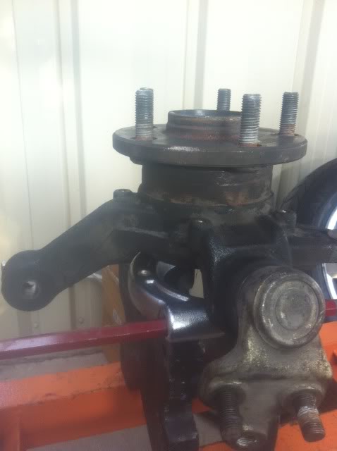
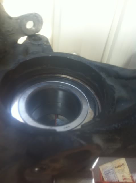
View from Other side of bearing with hub fully pressed in:
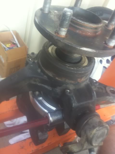
Step 29: Place dust shield back on:
Step 30: Bolt hub and knuckle assembly back on control arm and insert axel.
LASTLY:
Finish reattaching the tie rod end, strut bolts / nuts, speed abs sensor, and clip, rotor, and caliper.
AND FINALLY: Use the 30MM DEEP SOCKET to tourque down the axel nut. Once fully on, use a punch to hammer the "stop" in the axel's groove to prevent it from coming free.
YOU ARE DONE! Bolt on the wheel and you are done!
Step 23 - Remove last part of Bearing from hub. If you notice in the below photo, you will see that a part of the bearing remained on the hub. There are a few ways to get this off. I attempted to use separator halves to pry the remaining part of the bearing off the hub with no luck. So, in the pic below you will see where I used a cutting wheel to cut into the bearing. You do not need to cut through the entire thing, and be careful not to cut into hub. Simply cut about half way or so and used a flat head to pry in the cut area. This will cause the bearing to break and loosen to slide off.
Step 24: Press remaining bearing out of knuckle assembly. To do this, you may need to use the part of the bearing that you removed from the hub. Simply place it back on top of the ball bearings. Then place a LARGE LARGE socket or bearing ring which =should cover nearly the entire bearing. make sure you are pressing the correct direction. See photo.
I pressed this very hard and then it will eventually give and slide its way out. Takes nearly 12 tons, or so.
See blank Knuckle:
Step 25: CELEBRATE!!! The hard part is done!
Step 26: Press new bearing in. Notice that the knuckle is facing the opposite way as the press out. You will press the bearing in ALL THE WAY until the lip catches it. You can use the same socket or bearing ring you used to press it out, to press it in. Just be careful that the bearing does not bind going in. It should slide fairly easy in.
See below photos:
Notice the ring lip is above the bearing when it is completely pressed in. You should notice the color change.
Step 27: Place keeper ring back in (see earlier step and do in reverse).
Step 28: Press Hub back into bearing / knuckle assembly. See photos. Note I used my metal plates, and separator to cradle the knuckle. I used a large socket on the hub side to help press the hub in. MAJOR NOTE: Use a socket that is the correct size for the INTERIOR portion of the bearing on the UNDER SIDE (opposite of press side) to prevent the INTERIOR PORTION of the bearing from giving way and coming out as you press the Hub into the bearing. I used a short 30MM socket for this.
It will take quite a bit of force to free the bearing. See photos for better explanation:
View from Other side of bearing with hub fully pressed in:
Step 29: Place dust shield back on:
Step 30: Bolt hub and knuckle assembly back on control arm and insert axel.
LASTLY:
Finish reattaching the tie rod end, strut bolts / nuts, speed abs sensor, and clip, rotor, and caliper.
AND FINALLY: Use the 30MM DEEP SOCKET to tourque down the axel nut. Once fully on, use a punch to hammer the "stop" in the axel's groove to prevent it from coming free.
YOU ARE DONE! Bolt on the wheel and you are done!
Last edited by HtownBlue; Jun 4, 2011 at 09:15 PM.
Thread Starter
Lead Lap
Joined: Mar 2011
Posts: 537
Likes: 83
From: Texas
A couple of final notes:
Symptoms: I was hearing a noise related to the rotation of the wheels. It had a distinct pitch related to the speed of the wheel turning. It did not matter if the vehicle was in neutral, low, reverse, etc. the noise still persisted, which helped me rule out a tranny issue.
Sound was kind of like : whooo WHOOO whooo WHOOO whoooo WHOOO whooo WHOOO and pitch varied upon speed and turning angle of wheel.
Second note: I took off the dust plate for the sake of photos. I cut a small portion out of it so I could replace it afterwards after reattaching the HUB. You cannot take off Dust plate until HUB is removed, unless you "modify" it.
Last edited by HtownBlue; Jun 5, 2011 at 06:16 PM.
Trending Topics


Pole Position
Joined: Feb 2011
Posts: 254
Likes: 4
From: MN
Great job and thank you for the posting. By the way, how do you know you need to replace bearing? ANy symptom? Or just time/miles related.
Further does anyone know whether it is the same procedire for RX350 (07-09)?
Further does anyone know whether it is the same procedire for RX350 (07-09)?

Outstanding work! Thanks for posting the pictures.
I would suggest an easy way to remove the brake disc (step 5) is by threading in a pair of metric screws into those two small holes between the lug studs. I don't recall the size off hand, but I suspect they might be 6mm. Someone else might know. Makes very easy work of pulling the discs off the hubs without hammering on your discs.
Chris
Last edited by rxpx40; Jun 5, 2011 at 10:15 AM. Reason: clarity