
99 GS400 SRT intake question please help


Thread Starter
Pole Position
Joined: Jun 2006
Posts: 214
Likes: 0
From: TEXAS
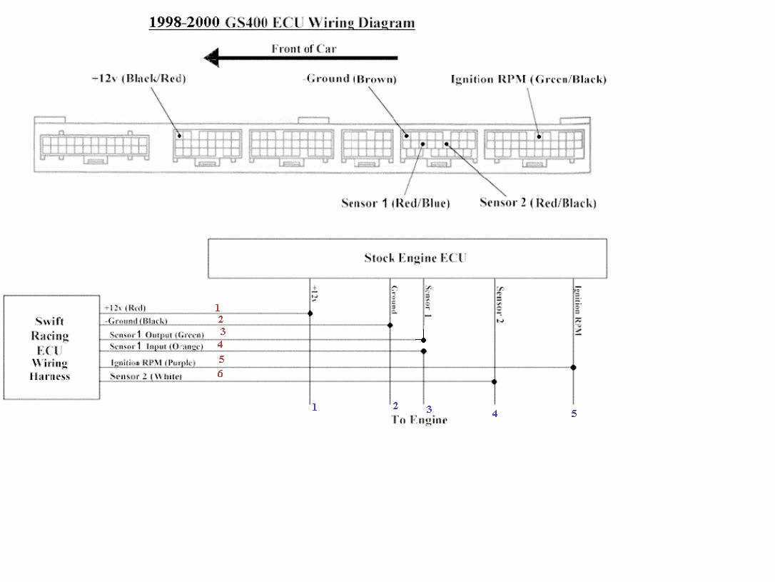
Question about cutting the single wire, according to the installation instruction say to cut 1 wire only. The ECU wiring diagram show 5 wires need to be solder from the swift racing wiring harness, but the swift wiring harness has 6 wires ? Where is the last wire connect to (sensor 1 input orange) ? Is that the wire that u cut ? I am little confuse on that 

Lexus Test Driver
Joined: Sep 2005
Posts: 1,144
Likes: 2
From: Plano, Texas
I am looking directly at the wiring diagram. There are 6 wires from the swift ECU. You need to connect 4 of those wires directly to wires in your engine ECU. The last 2 wires(sensor 1 output and sensor 1 input) connect to the wire that you have to cut. You will cut Sensor 1 wire in half that goes from your engine ECU to your engine. You will connect SRT Sensor 1 Output to the cut end of your engine ECU sensor 1 wire that will be hanging from your Engine ECU. You connect the SRT Sensor 1 Input wire to the sensor 1 wire that will be hanging from your engine harness. Do you have the wiring diagram?


Joined: Feb 2001
Posts: 31,944
Likes: 2,737
From: North Carolina
TexasGS, I'm not sure how different they are (other than to know they are two different products sold by SRT), but the original poster has a GS400 and you're probably looking at a GS430 diagram.
Lexus Test Driver
Joined: Sep 2005
Posts: 1,144
Likes: 2
From: Plano, Texas
Yes, I am looking at a GS430 diagram but I think they are basically the same. The wire colors are the only thing that is different....I think ") . The quantity of wires and how they are wired is the same. Heck the wire colors on my diagram did not even match with my car. I think he was just confused with the Sensor 1 wire that needed to be cut. That is typical for all SRT ECU's.
. The quantity of wires and how they are wired is the same. Heck the wire colors on my diagram did not even match with my car. I think he was just confused with the Sensor 1 wire that needed to be cut. That is typical for all SRT ECU's.
. The quantity of wires and how they are wired is the same. Heck the wire colors on my diagram did not even match with my car. I think he was just confused with the Sensor 1 wire that needed to be cut. That is typical for all SRT ECU's.
Trending Topics
Thread Starter
Pole Position
Joined: Jun 2006
Posts: 214
Likes: 0
From: TEXAS
thank you guys for the help , i will try continue working on it when i get a chance  Hey Texas GS my diagram shows 5 wires from the SRT wiring harness connects to the ECU not 4 like u said.
Maybe 430 and 400 is a little diff ? My question was i wasnt sure where the last wire (Sensor 1
input orange) connects to ?
Hey Texas GS my diagram shows 5 wires from the SRT wiring harness connects to the ECU not 4 like u said.Maybe 430 and 400 is a little diff ? My question was i wasnt sure where the last wire (Sensor 1
input orange) connects to ?
Last edited by AW99GS400; Aug 1, 2006 at 01:50 PM.


Lexus Test Driver
Joined: Sep 2005
Posts: 1,144
Likes: 2
From: Plano, Texas
Originally Posted by AW99GS400
thank you guys for the help , i will try continue working on it when i get a chance Hey Texas GS my diagram shows 5 wires from the SRT wiring harness connects to the ECU not 4 like u said.
Maybe 430 and 400 is a little diff ? My question was i wasnt sure where the last wire (Sensor 1
input orange) connects to ?
Hey Texas GS my diagram shows 5 wires from the SRT wiring harness connects to the ECU not 4 like u said.Maybe 430 and 400 is a little diff ? My question was i wasnt sure where the last wire (Sensor 1
input orange) connects to ?
 . On the 430 you cut Sensor 1 and connect 2 of the 6 wires to each end of the cut Sensor 1 wire. The other 4 wires tap into the ECU wiring. I guess someone with a 400 wiring diagram needs to pipe in here.


Originally Posted by AW99GS400
Question about cutting the single wire, according to the installation instruction say to cut 1 wire only. The ECU wiring diagram show 5 wires need to be solder from the swift racing wiring harness, but the swift wiring harness has 6 wires ? Where is the last wire connect to (sensor 1 input orange) ? Is that the wire that u cut ? I am little confuse on that
As you notice wire 3 and 4 from the the SRT ECU connects to wire 3 ( ONE WIRE)to the engine.
 i got it now

Thread
Thread Starter
Forum
Replies
Last Post