When you click on links to various merchants on this site and make a purchase, this can result in this site earning a commission. Affiliate programs and affiliations include, but are not limited to, the eBay Partner Network.
Finally found an instrument cluster at a decent price. Picked up a bezel as well. You can probably guess part of what I am planning to do, but can you guess the rest?
Let’s hope you’re going to snap your fingers, twitch your nose and voli� you’ve magically turned a 02-05 combination meter into a 06-10 facsimile, YES? Or, something more scientifically repeatable?
Let’s hope you’re going to snap your fingers, twitch your nose and voli� you’ve magically turned a 02-05 combination meter into a 06-10 facsimile, YES? Or, something more scientifically repeatable?
Well, minus the nose-twitching and finger-snapping, that's the first part of the plan, yes. Sort of. My understanding is that the 06+ instrument clusters are electro-luminescent. That's really not too difficult, but I am going to try just brightening the LEDs first. Where I think others may have failed is that you need to change the resistors used, not just the LEDs especially if you use white or blue LEDs. They have a higher voltage drop, so using the same resistors would be even less current through them. You should also use wide angle LEDs.
I swear I saw some guide on here that showed how to get those needles off without breaking them.
Good old fashioned prying (carefully) did the trick.
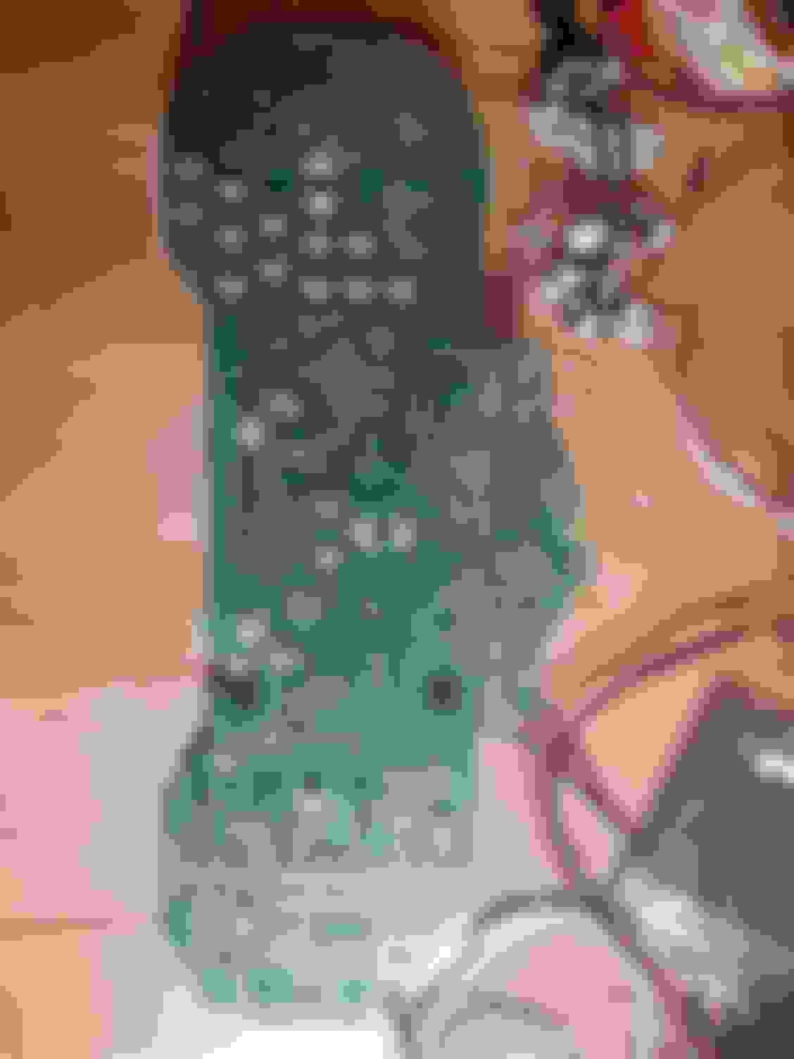
I didn't get a good angle here, but there are many LEDs that are not populated. Especially in the shifter section. Notice also that there is a connector for another display under the shifter section. Unpopulated.
Here you can see what I am talking about better. All of the LEDs have letters beside them like R, W, G for the color. The LEDs are all 2.7x3.3mm (i have to look up the package size. I forget. Resistors are on the back side of the PCB.
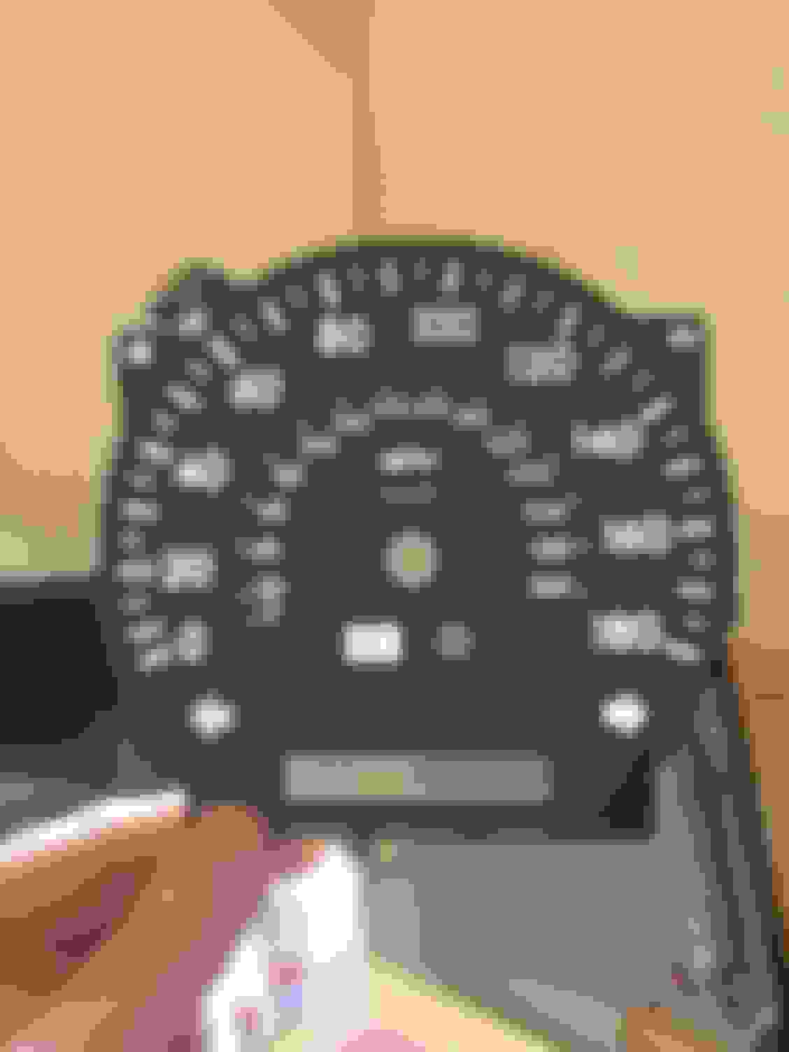
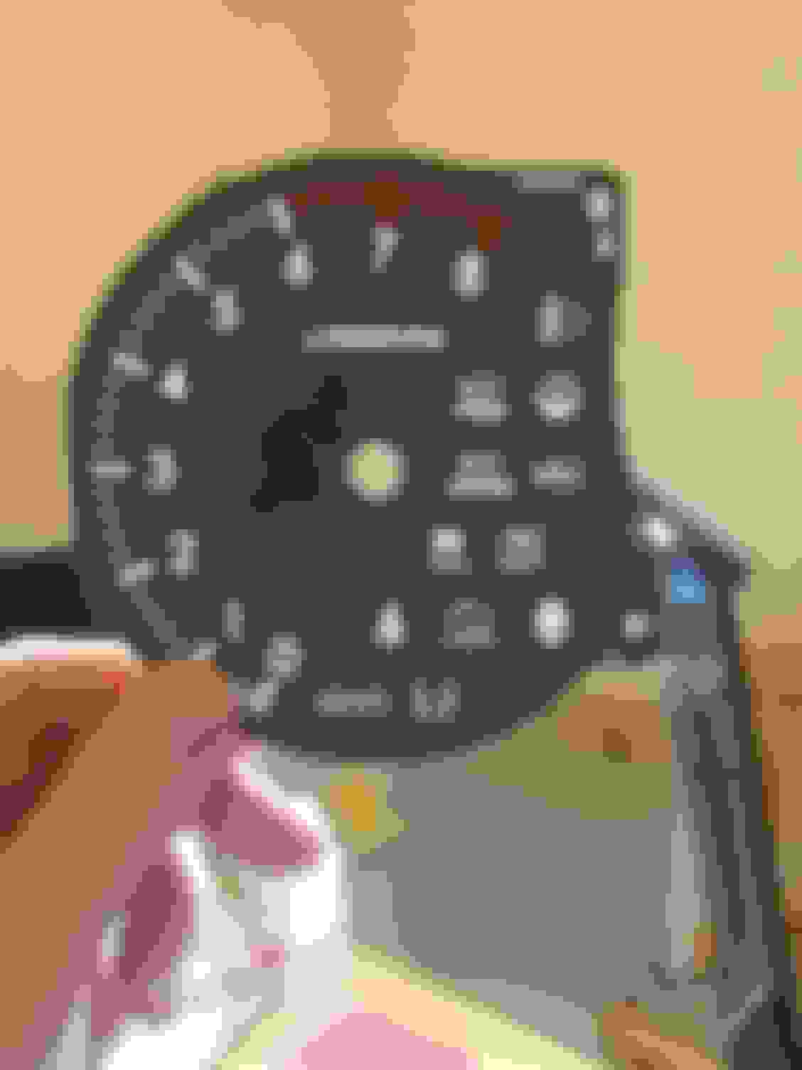
Below are just pics of the different gauges showing all elements that are present.
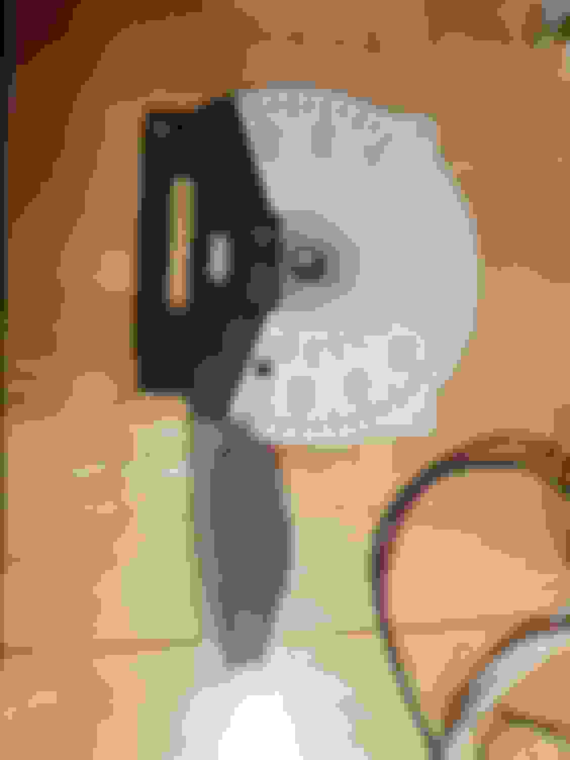
These appear to be multiple layers of styrene or maybe PVC to built up a mask. Notice that white block just above the display. That is actually opaque and lines up with the display. Probably for the compass option.
The LCD itself appears to be two lines with possibly some icons at the top. If you look back at the PCB, you will notice that it is a missing a chip. I believe that it the compass. Using static from my fingers, I activated some of the LCD elements and noticed they are capable of full text
The window in the gauge only allows the bottom line to be seen, however. I will hook this up and play with it a bit. I am intriqued.
The package is called 1311 (3227). Some PLCC-2 sizes would work, but stick around 32x27mm. The 32 part (length) is the most important dimension.
Resistors are almost all 620 ohm. At 12V, that would provide about 16-18mA (depending on LED color). Max would be about 30mA for red and 25mA for green. Amber is about 25mA too, usually.
For white LEDs which have about a 3V voltage drop... 12V - 3V(LED drop) = 9V. 9V / 25mA = 360 Ohm is probably the safest level. Manufacturers for most LEDs say to stick with 20mA but that is for the longest life.
If you wanted to go with Electroluminescent, you would buy something like this https://www.adafruit.com/product/625.and then cut it to the shape of the gauge faces. The EL panels are thin enough that you could just put them right under the faces. It would be best to leave some LEDs like the red etc.. and just punch those out of the panels.
You would need to power them off inverters and dimming them might be a little bit of a challenge if you wanted that. Otherwise, you would just use the illum signal as a trigger for the inverters.
This is not what I am planning to do. What I want to figure out is how to black out the cluster and have the LEDs "chase" the needles or get rid of the needles altogether just lighting the individual notches to indicate speed/rmp, etc.. Or even come up with something completely digital. My over all goal is to reduce the amount of light inside the car as much as possible without giving up important info.As well as give it a more modern look.
So my first question is: Do you think the 06-10 gauge faces are same or similar construction?
I haven't seen the insides of an 06-10, but I would expect that it would be similar. If it IS using electroluminescent, the circuit board would be quite different. There would need to be transformers on the board. It would probably be much easier if someone wanted EL to get an 06-10 and downgrade it rather than upgrade a 02-05
If someone wants to donate one to the cause, I would be certainly willing to find out if it is possible to swap in a 2006-2010 instrument cluster.
Looking at them on eBay, they actually seem to be blacked out. That may add to the contrast of making them appear so much brighter.
I also see people referencing mileage programming of the IC. I do see the little EEPROM on here that must store the mileage.
I am really curious what that other display under the shifter would have been. I have a co-worker that used to work at Denso making clusters for Toyota. I will bring it in and talk to him today.
EDIT: I should say 06-07. All listings seem to say that, so there must be something different in the 08-10 IC. I don't see any of those listed, however. I do see a Soarer IC listed with a different shift indicator arrangement, though.
In 2006, Lexus figured it out, and re-designed the gauges. The �06-�10 SC430 clusters now adopted the �optitron� technology. The only issue is that the two clusters are NOT, and in NO WAY, a direct plug and play. How so? Here�s a few major reasons�
(1.) The warning indicator lights don�t match up; many of them are unique to each model year.
(2.) The tachometer �movement,� in terms of degree rotation, doesn�t match up, so a lot was needed to calibrate the needle movement to accurately display the right tach readings.
(3.) The stepper motors that move the needles aren�t compatable, so I had to transplant and wire the old motors from the old cluster circuit board into the new cluster type circuit board. Literally, behind that cluster there are TWO clusters; the original, and the new. With wires going between them.
(4.) The P-R-N-D-4-3-2-L indicators for the 5-speed transmission of the �02-�05 needed conversion to display �appropriately� on the P-R-N-D-S indicators of the �06-�10 6-speed clusters.
(5.) The LCDs for the mileage aren't compatible. The one on the old cluster is triangular in shape, to fit data on Canada built clusters (it just appears rectangular on the old type cluster because the face plate covers the top). So, i had to transplant the old LCD into the new cluster. Which caused trouble as the triangular LCD blocked the icons for CRUISE and LIGHTS ON. It was hard to make those icons still light up.
But after countless hours, three donor clusters, yards upon yards of wiring for each of the warning lights, and a week�s worth of f-bombs, I DID IT!!!!!!!!

 03-19-18, 03:52 PM