
Nav and AC buttons voltage


I know RKW should be the first to jump and answer this for me ;D I'm depending on you buddy!
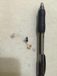
Anyways, I'm taking my NAV apart and changing all those green (orange bulbs with green cap) to white LED's, and it hasn't been going good for the last 3 days.
I have soldered so many type of LED's! Some burn, some light up and some don't.
I need to find what current is given to each bulb? Or at least, what is the forwarded voltage for the bulbs that were already on the board?


I hope he'd be able to give us insight on this one. MY NAV has been torn apart for 4 days now.
Problem is I can't get a standard reading from the board, thus I can't find the right LED or bulb.
Problem is I can't get a standard reading from the board, thus I can't find the right LED or bulb.


Pit Crew


Joined: Dec 2006
Posts: 192
Likes: 51
From: HI
Aloha,
Received your PM. I am not a pro so my verbiage may be wrong at times along with my advice but anyhow, Its strange that you are getting multiple voltage reading. In the second picture that has the led's lit up, you are checking DC current on the leads coming out the LED right?
Also in the second picture, the two LED's that are not on, did you solder those? Im assuming you did. You do not need resistors on both leads, in fact you probably don't need resistors at all as boards usually have some sort of voltage regulator to properly power up the leds with proper voltage.
Anyway:
1. Your going to have to find the voltage going to each led for starters. Use your multimeter in VDC and power up the board. Check the leads on both the contact points to the led that is burnt out AND the ones that are running.
2. Once you figure this out, you can find out what type of LED replacement that operate in that range.
3. are all the other lit up LED's already been changed by you? Or are the lit ones factory?
Daniel, thanks for checking the thread, any help is much appreciated.
So I de-soldered everything from the board. Took it to the car and connected it to the power source.
I started from the bottom using my voltmeter to get readings.
1-The first one gave me 13.8 volts.
2- second one to the right gave me 9 volts.
3- third one gave me 6.4 volts.
4- fourth one gave me nothing.
5- and the fifth one(furthest one to the top) gave me 9.3 volts.
At this point, the clock stopped working. Which made me think, I think I must've shorted something out in the board!
The map buttons(ones to your right) don't light up at all.
What am I missing here?
Does the clock have a fuse?
Trending Topics
Driver
Joined: May 2014
Posts: 108
Likes: 2
From: Poland
Recently I was trying to replace this bulbs to white cold LED also.
But it is not so easy. In radio it is possible to use 12V LED. But you need to make some shorts and remove 2 resistors. Bulbs are in groups (three bulbs in one group). They are connected parallel, but at the beginning is resistor. You must remove it and short by wire.
In navi on one site there are groups with 2 bulbs with serial connection. There is possibility to make some shorts and use 12V LED. But on the other side there is couple of groups with resistors and it quite difficulty to find all paths (2 layers).
I gave up. Mayby I will try again on free time. All bulbs are 6V. I think, the easiest way it will be to measure bulbs resistance and find resistors which connected to LED gave the same power output as the bulb. But it will gave 6V. So it must be serial-parallel connection to get specific output voltage on led connector.
Recently I was trying to replace this bulbs to white cold LED also. But it is not so easy. In radio it is possible to use 12V LED. But you need to make some shorts and remove 2 resistors. Bulbs are in groups (three bulbs in one group). They are connected parallel, but at the beginning is resistor. You must remove it and short by wire. In navi on one site there are groups with 2 bulbs with serial connection. There is possibility to make some shorts and use 12V LED. But on the other side there is couple of groups with resistors and it quite difficulty to find all paths (2 layers). I gave up. Mayby I will try again on free time. All bulbs are 6V. I think, the easiest way it will be to measure bulbs resistance and find resistors which connected to LED gave the same power output as the bulb. But it will gave 6V. So it must be serial-parallel connection to get specific output voltage on led connector.
I took everything to an electrician and had them take a look at this mess.
Since the clock stopped working, and some LED's work and some don't. He has finalized the problem as "new LED's didn't have the same MA Milliamps as the older stock ones, therefore, the circuit has been overdriven causing problems where stuff might stop working and where some bulbs work and some don't."
He blamed it on the MA, said to measure the old bulb's MA, then get an LED accordingly. Preferably with the same footprint.
Now, my NAV works perfectly, except for the buttons on ones side do not work. And I need to buy a new one.
Found a used one on eBay for $200. Have to get it and then try again.
If anyone wants buy mine, I'll be happy to sell it.
Hopefully I'll update this thread with any progress.
Because just finding the right voltage won't do good in this case. This seems to be a very sensitive circuit board. We need to find the right forwarded voltage AND the right Miliamps consimption(same MA as stock bulb).
On the other hand, I read that the RX vehicles come equipped with Aqua white radio buttons. So the same tiny bulbs with the plastic base, but not ORANGE like ours, instead it's in AQUA WHITE. So that seems to be an option of a direct swap.
The question is; Does anyone know where we can get our hands on component parts like this. I haven't contacted a dealer yet. But I'll get in touch with South Atlanta and Sewell and see if they would be able to supply the parts.
Talked to Sewell, and they said that this part won't be available from Lexus. And the best bet would be to measure the specifications of this bulb and try to find a replacement then.
Only if there was a way to get in touch with the manufacturer.
Only if there was a way to get in touch with the manufacturer.
