


LS430 Brake Pad Replacement w/ Photos


Thread Starter
Driver


Joined: Jan 2007
Posts: 156
Likes: 15
From: TN
 LS430 Brake Pad Replacement w/ Photos
Based on the information found in this thread I decided to do my own pads, and while I was at it, take photos so I could create a new thread with the steps and photo set.
So without further ado, here's my write up-
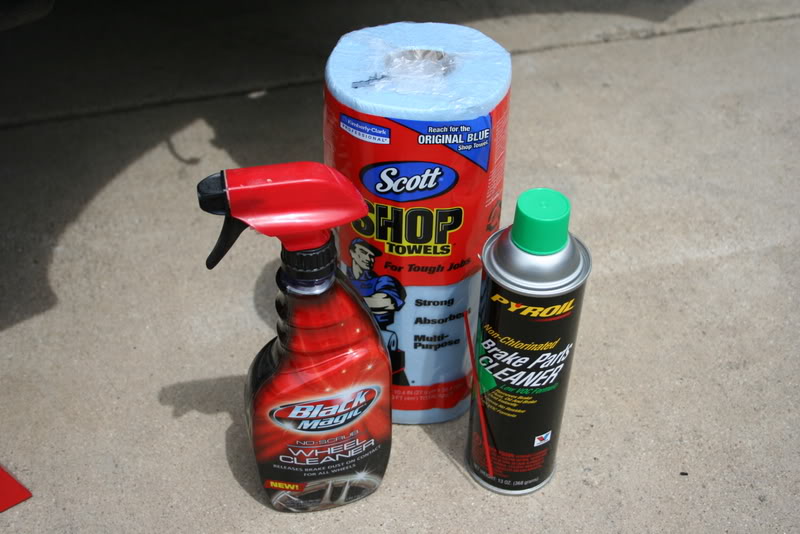
The tools-


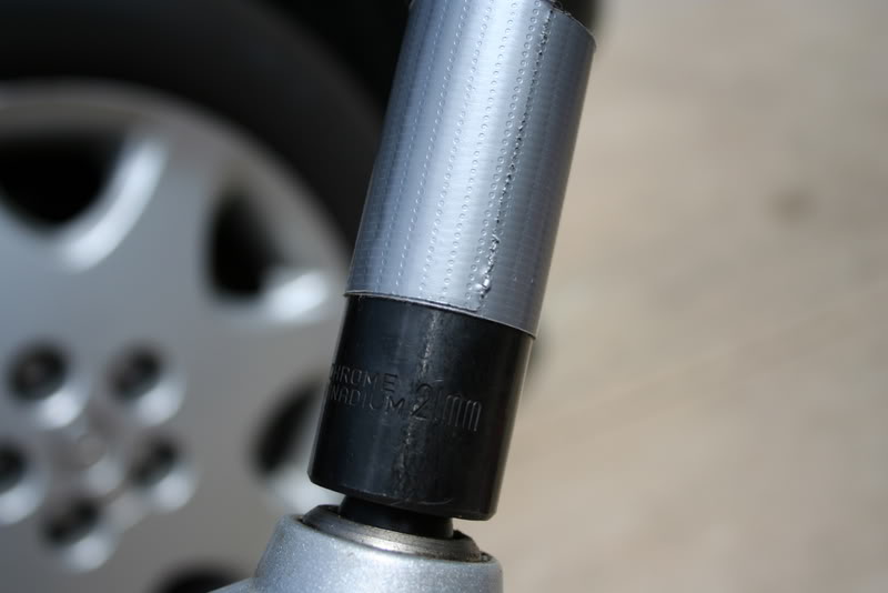
21mm socket with tape to protect wheel finish-
Chassis Jacking Point-
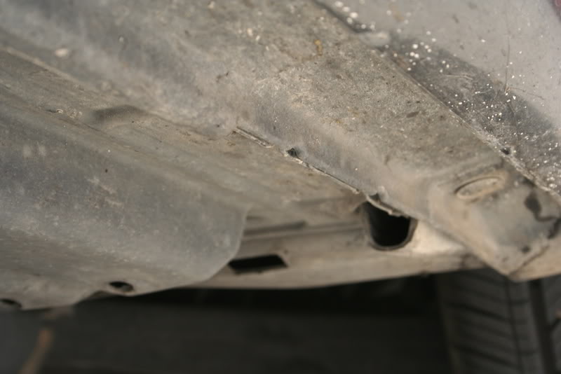
Jacked car up and placed jackstand under chassis-

Opened master cylinder fluid reservoir-

Onto next step- front axle brake replacement
So without further ado, here's my write up-
The tools-
21mm socket with tape to protect wheel finish-
Chassis Jacking Point-
Jacked car up and placed jackstand under chassis-
Opened master cylinder fluid reservoir-
Onto next step- front axle brake replacement


Thread Starter
Driver
Joined: Jan 2007
Posts: 156
Likes: 15
From: TN
Front Brakes
Remove the front wheel-
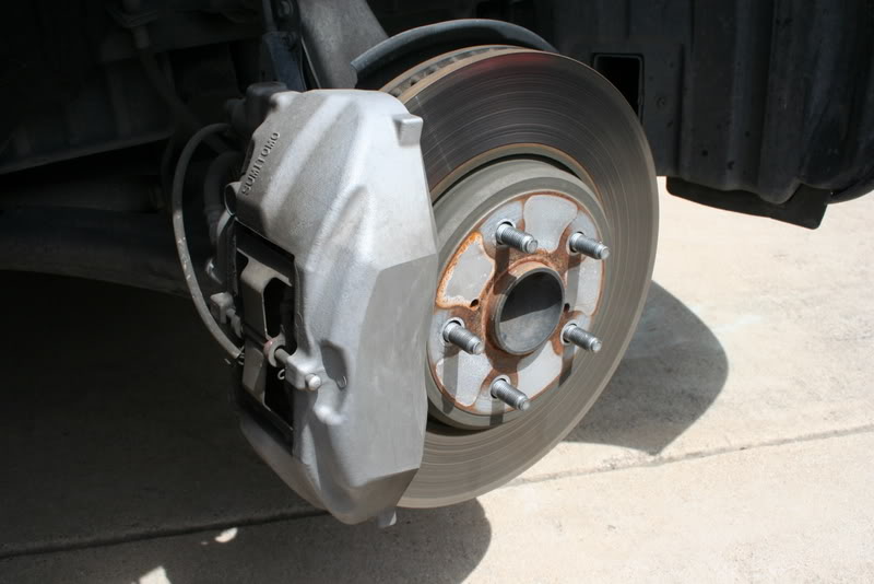
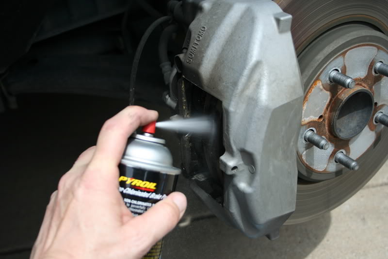
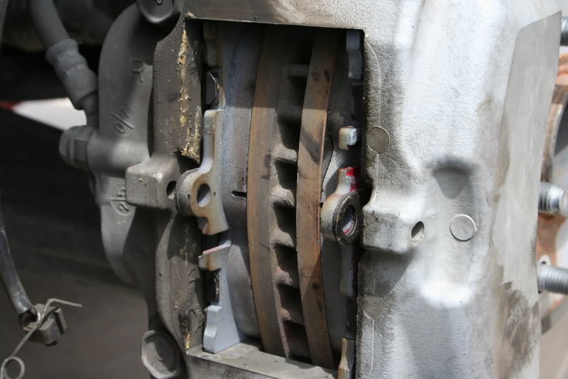
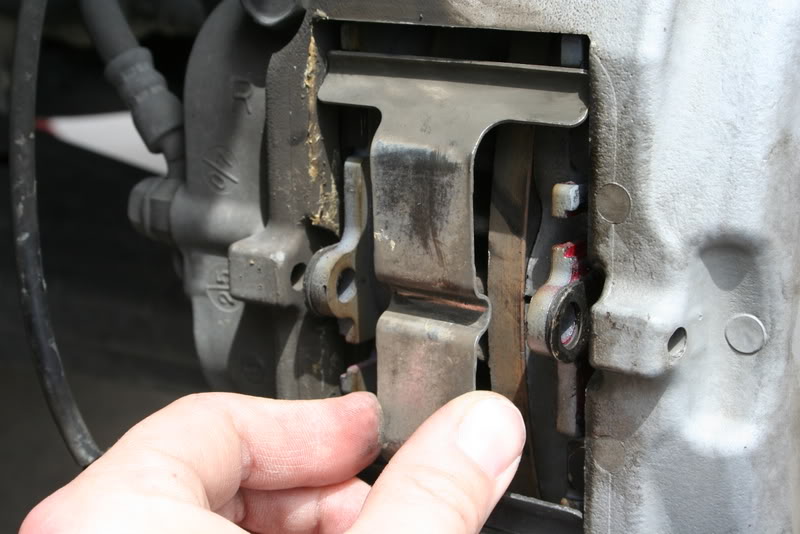
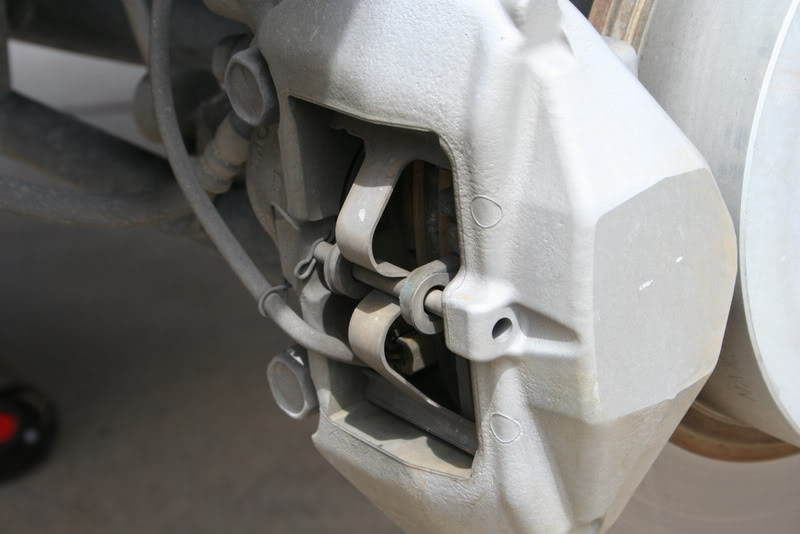
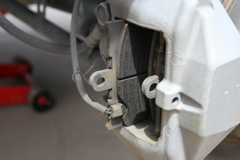
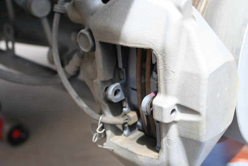
Caliper Detail-
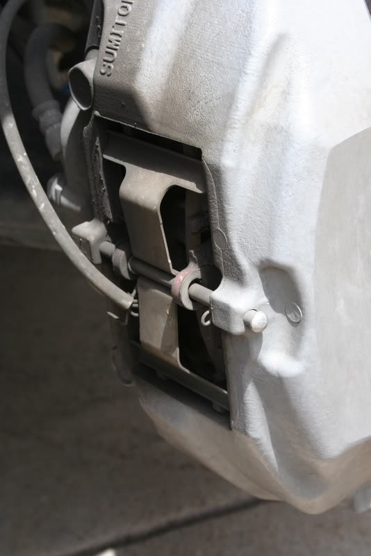

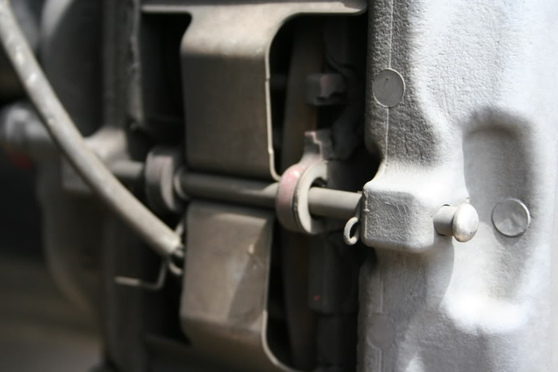
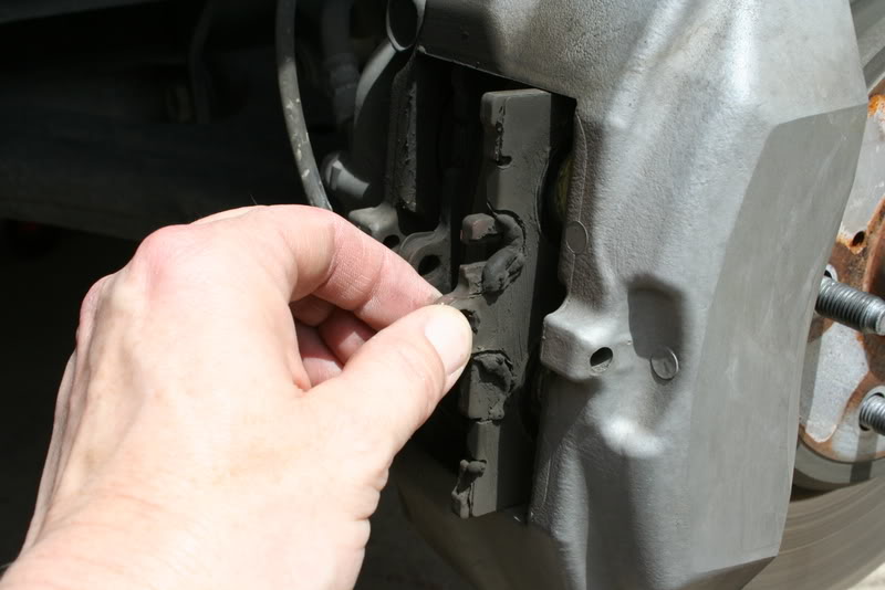
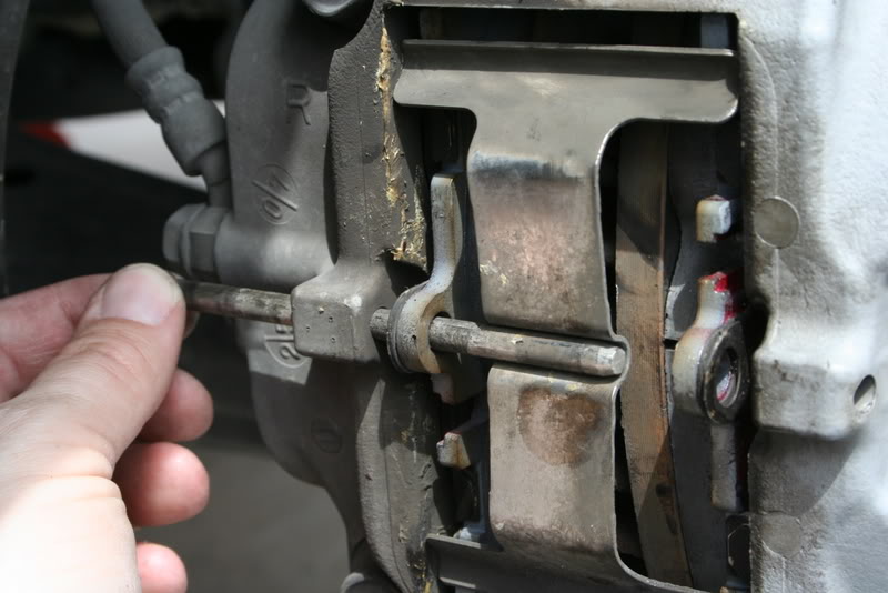
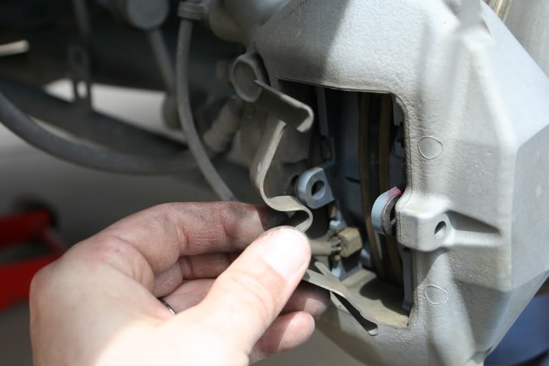
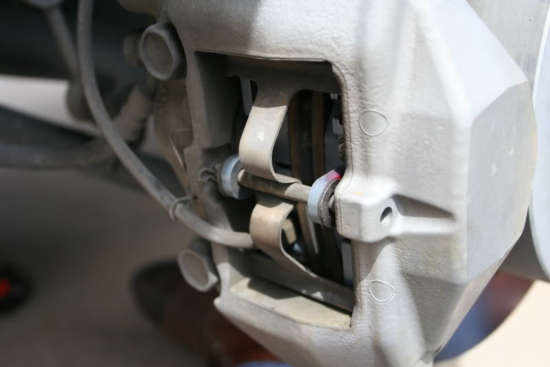
At this point, based on previous pictures I have seen, the pin retaining the pads was inserted backwards (from the front, not the back).
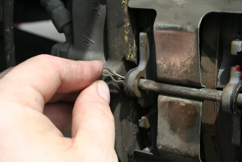
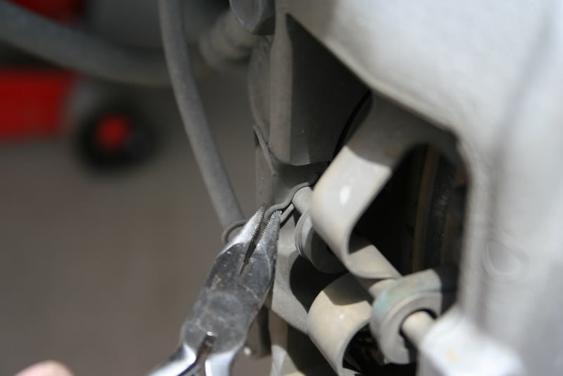
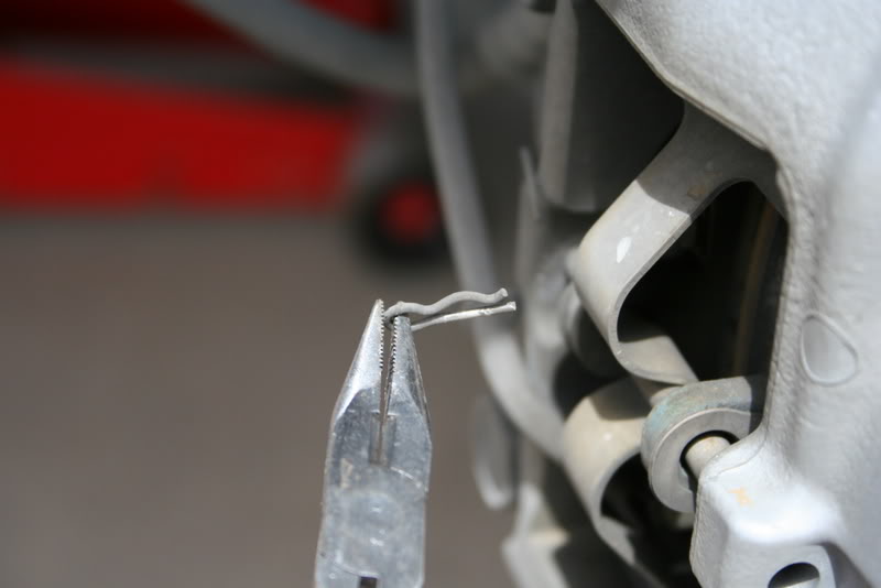
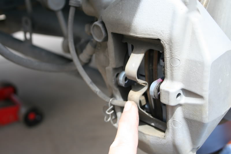
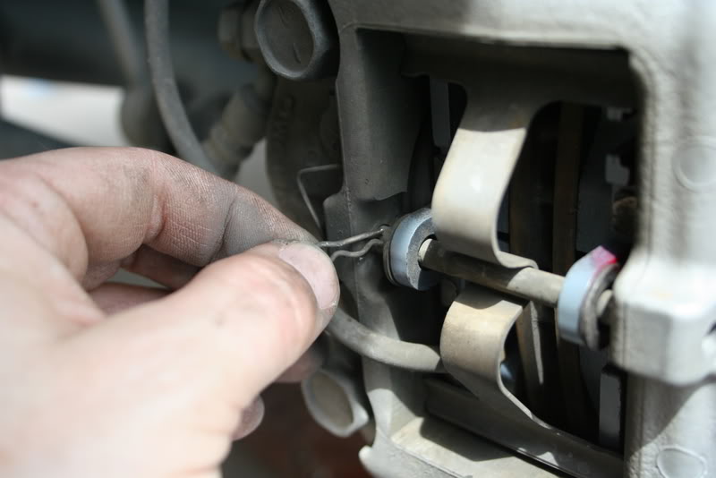
Remove the clip holding the pin in place-
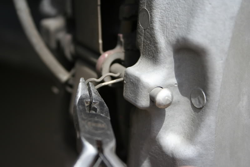
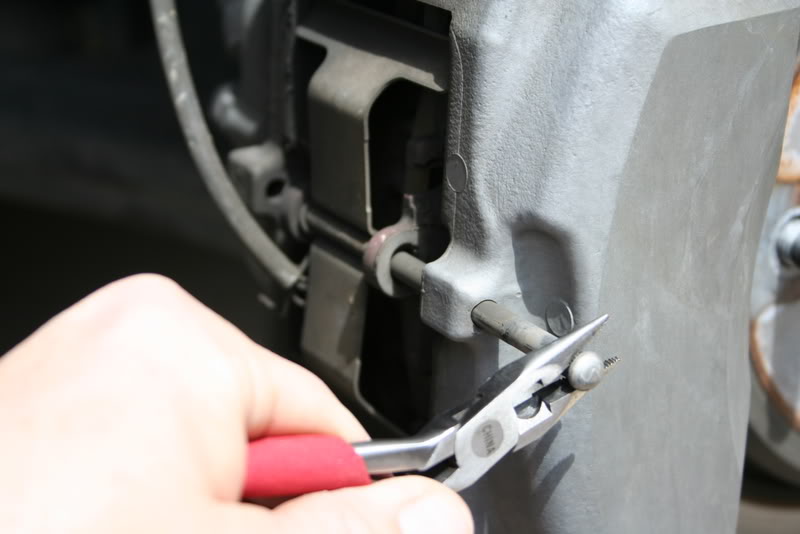
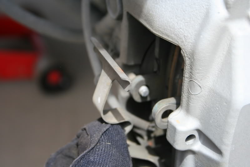
And remove the pin (can be done by hand if you place pressure on the plate holding the pads in)
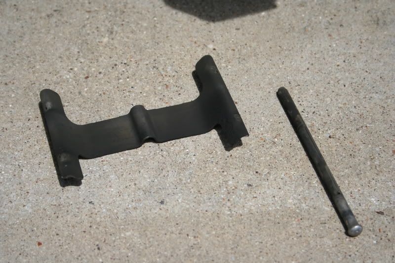
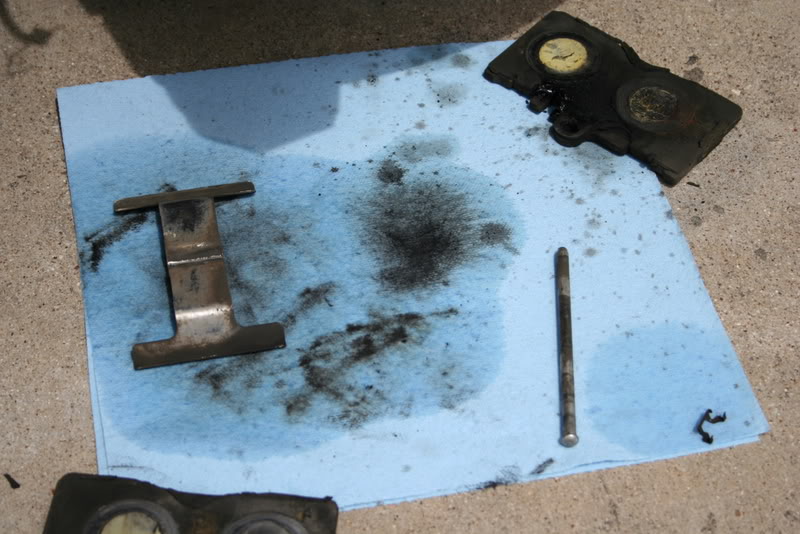
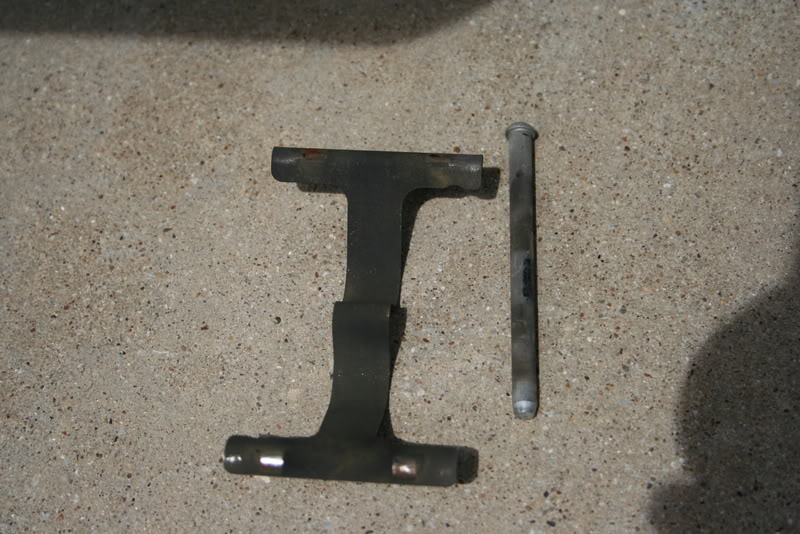
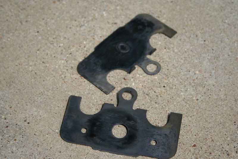
Set aside pin, clip, and retainer plate-
Caliper Detail-
At this point, based on previous pictures I have seen, the pin retaining the pads was inserted backwards (from the front, not the back).
Remove the clip holding the pin in place-
And remove the pin (can be done by hand if you place pressure on the plate holding the pads in)
Set aside pin, clip, and retainer plate-










Trending Topics
Thread Starter
Driver
Joined: Jan 2007
Posts: 156
Likes: 15
From: TN
The aftermath-
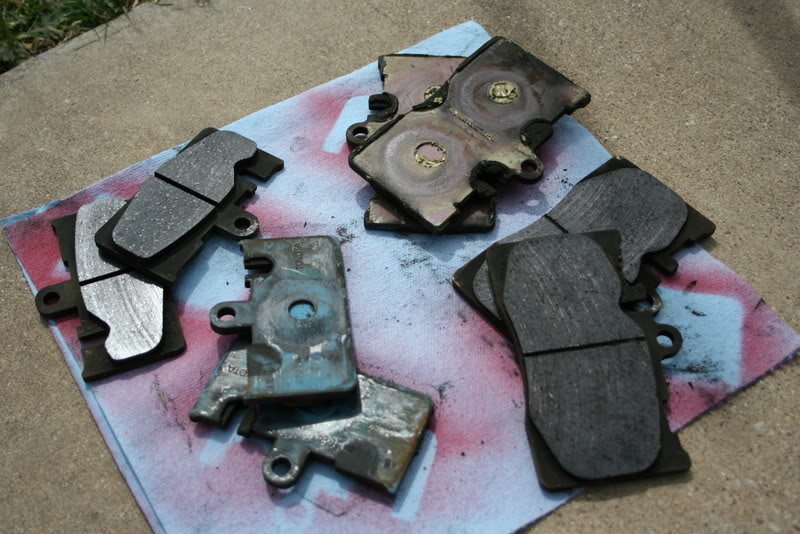
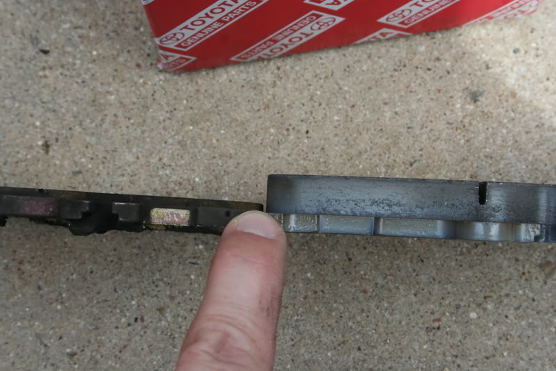
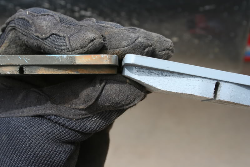
For reference, the pads I replaced had at least 75,000 miles on them.
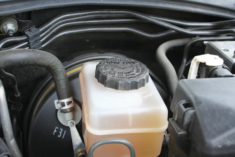
Don't forget to put the cap back on the fluid reservoir- (note fluid level after pad change)

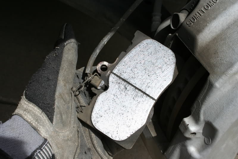
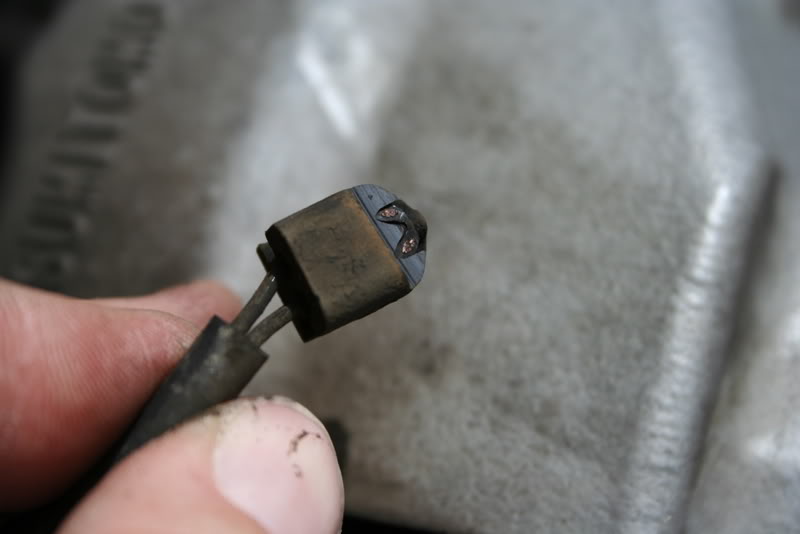
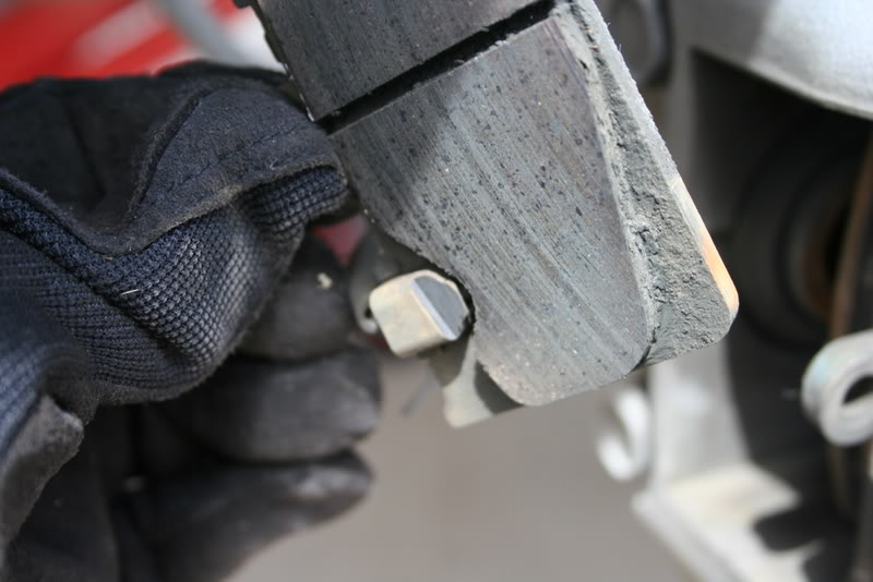
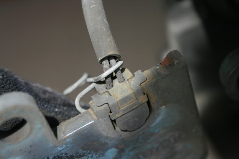
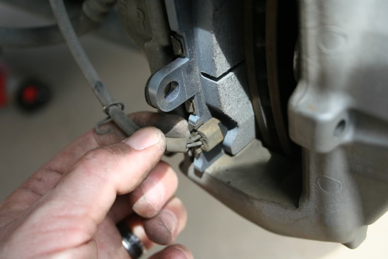
Sensor detail (front pad)
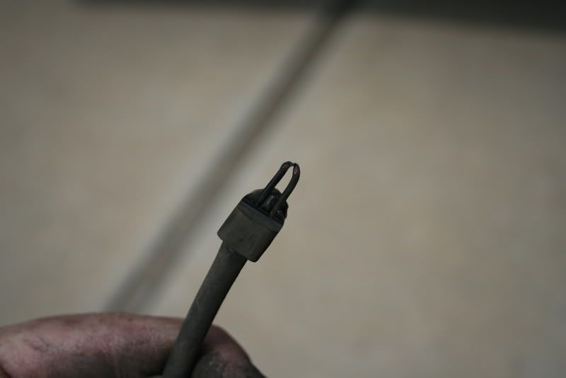
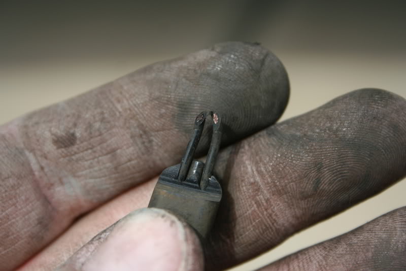

Since the pads lasted as long as they did, I didn't rush out to buy a new sensor. Looking at it, it's basically a copper wire loop in plastic that once worn through, makes the dash light appear. I pushed the wire through the plastic "pad" and cut the loop, removed the plastic "pad" and used a butt splice and joined the two wires. I then zip-tied the sensor to the spindle upright making sure to avoid areas that might rub. Voila- no more light, and I'm a big enough boy to remember to check my pads on occasion.
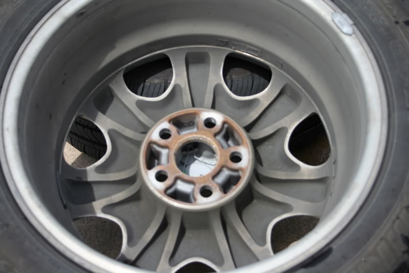
While they were off, I decided to clean/wax/and rotate my wheels-


For reference, the pads I replaced had at least 75,000 miles on them.
Don't forget to put the cap back on the fluid reservoir- (note fluid level after pad change)
Sensor detail (front pad)
Since the pads lasted as long as they did, I didn't rush out to buy a new sensor. Looking at it, it's basically a copper wire loop in plastic that once worn through, makes the dash light appear. I pushed the wire through the plastic "pad" and cut the loop, removed the plastic "pad" and used a butt splice and joined the two wires. I then zip-tied the sensor to the spindle upright making sure to avoid areas that might rub. Voila- no more light, and I'm a big enough boy to remember to check my pads on occasion.
While they were off, I decided to clean/wax/and rotate my wheels-


Thread Starter
Driver
Joined: Jan 2007
Posts: 156
Likes: 15
From: TN
After replacing the wheels and properly hand tightening them, I took a drive to "bed" in the brakes and check proper operation. No issues and brakes worked like a charm.
Tips- Use the right tools. Take your time. Work cleanly. Work safely.
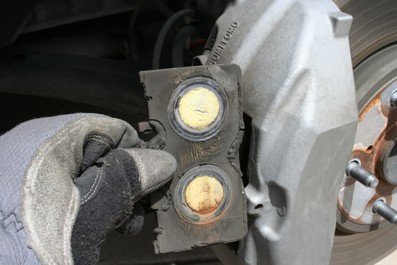
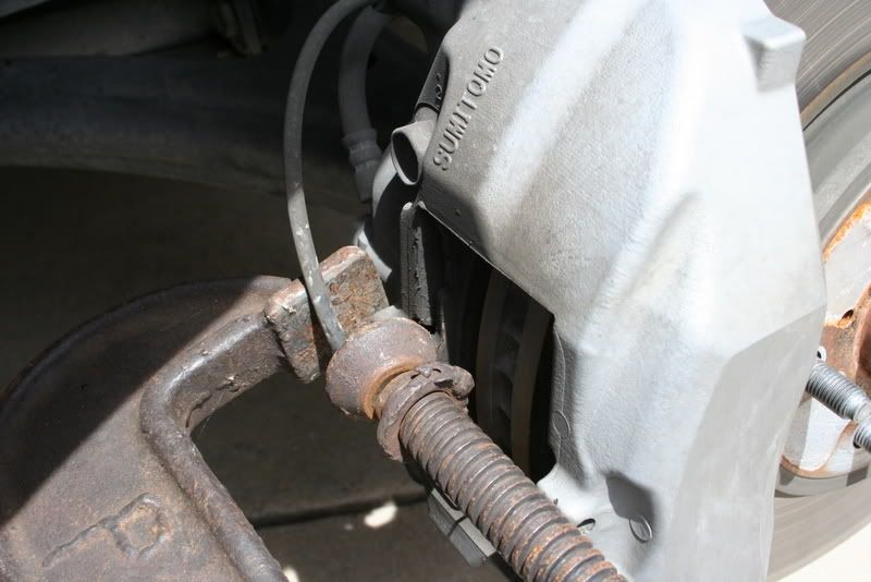
When installing the front pads, and compressing the pistons, I used an old pad to apply pressure to push the pistons into the caliper equally. Pushing in on them individually only caused the other piston to push out.
No major headaches, and after changing countless pads in a variety of vehicles over the past 25 years I have to say this is the easiest pad replacement I have ever done.
Pads purchased from Iron Toad.
If I think of anything else, I'll edit. Hope someone finds this as useful as I did the other posts on the subject.
Todd
Tips- Use the right tools. Take your time. Work cleanly. Work safely.
When installing the front pads, and compressing the pistons, I used an old pad to apply pressure to push the pistons into the caliper equally. Pushing in on them individually only caused the other piston to push out.
No major headaches, and after changing countless pads in a variety of vehicles over the past 25 years I have to say this is the easiest pad replacement I have ever done.
Pads purchased from Iron Toad.
If I think of anything else, I'll edit. Hope someone finds this as useful as I did the other posts on the subject.
Todd


 x2
x2

Lead Lap
Joined: Mar 2006
Posts: 4,189
Likes: 16
From: NY/NJ
So when you use the c-clamp to push the pistons back, you basically just use the old pad and compress that against the caliper's pin slot to push the piston back? Very nice that you don't even have to remove the lower flange pin and rotate the caliper up to push the pistons in. Looking at picture, I guess the fronts are four piston while backs are two?
Excellent writeup and nice close pictures.
Excellent writeup and nice close pictures.
Thread Starter
Driver
Joined: Jan 2007
Posts: 156
Likes: 15
From: TN
So when you use the c-clamp to push the pistons back, you basically just use the old pad and compress that against the caliper's pin slot to push the piston back? Very nice that you don't even have to remove the lower flange pin and rotate the caliper up to push the pistons in. Looking at picture, I guess the fronts are four piston while backs are two?
Excellent writeup and nice close pictures.
Excellent writeup and nice close pictures.
I talked about this with my brother yesterday, he said the brakes on the LS were like the ones on his motorcycle as far as ease of maintenance.
Yes 4 and 2 piston respectively.
Todd
