When you click on links to various merchants on this site and make a purchase, this can result in this site earning a commission. Affiliate programs and affiliations include, but are not limited to, the eBay Partner Network.
The fuel PUMP is accessible by removing the back seat. But the SENDER is accessible from the trunk, on the rear surface of the tank. Complete opposite side from the fuel pump.
In case working with resistance is easier than voltage, here is some info from the 2000 manual:
B5 – B12
Fuel Sender Gauge
Float position Full - Resistance Approx. 21 Ohms
Float position 1/2 - Resistance Approx. 145.8 Ohms
Float position Empty - Resistance Approx. 276 Ohms
B5 – B13 Constant Resistance Approx. 300 Ohms
B5, B12, and B13 are the sender connection numbers at the Combination Meter (instrument panel). B13 will be 5V, B5 will be ground, and B12 will have the voltage read at the instrument panel.
The manual specifies simple troubleshooting steps (page BE104):
disconnect connector from sender (simulates infinite sender resistance, which is emptier than empty)
turn key to ON
gauge should indicate EMPTY
connect terminals 2+3 (sets the B12 signal to 5V, simulating zero resistance at the sender, which is fuller than full)
turn key to ON
gauge should indicate FULL
DO NOT CONNECT terminals 1 + 3 (+5V to ground)
And the manual does not say this, but of course if those previous tests vary resistance from infinity to zero, then using a potentiometer to vary B5-B12 between 21 and 276 Ohms should allow you to easily test the accuracy and linearity of the gauge.
My opinion on your idea to add a calibration potentiometer - It does not sound like the problem with your system is linear and correctable by gain and bias adjustment, as would be provided by adding variable resitances. You say it starts off full, then drops 1/4 tank within a few miles. Is it then linear from there down to empty? If yes, then a gain adjustment would work, but I would guess it is not linear.
Hi Oldskewel, I'm a bit confused, isn't the pump part of the fuel sending unit assy w/ the float & the 3-pin connector is routed & can be accessed from the trunk? As stated, I've replaced the fuel pump on my 97 Lexus LS400 a couple years ago. I've used an aftermarket hi-flow pump so I took out the whole fuel pump/sending unit assy & just replaced the pump. Car has been working great & the fuel gauge's display is dead-on accurate. Where is this built-in 300 Ohm potentiometer as I don't recall of seeing it? Is it a mechanical slider w/ the float ties to the center tap & its resistance will vary between the calibrated 21 (4.38V) to 276 Ohms (.48V) based on the fuel level in the tank? Anyway, for the 2000, when I get a chance to work on it, my plan was to remove the lining in the trunk to get access to the connector & from there, I can test the fuel gauge's display by pulling the output of pin 2 to 5V (zero resistance) & shorting it to ground (max resistance) for the gauge to swing between full & empty, respectively but I know it's working (it's just off) that's why I was thinking of filling up the tank & using an external 10K pot to re-calibrate/set the fuel gauge to 4.38V & assuming it will be a straight line (linear) all the way. Speaking about the fuel gauge's linearity & to answer to your question, my 2000 isn't my daily driver so I haven't checked to see whether it's linear from the point when I've noticed it was off to empty. I'll keep an eye on it when I drive it more.
Hi Yamae, my fuel gauge is working & based on Oldskewel's comment, it has got me thinking that perhaps the reason it's slightly off could very well due the the infamous electrolytic capacitor(s) start going bad since the car is 17 years old even though it's in pristine condition & low mileage. Are they part of the 11 caps reside in the ECU or are they on a separate board for the instrumentation panel? I may pull it out for a visual inspection. On a 2nd thought, if I pull it out, might as well order the new caps & replace them. Please advise on the location & values of these caps.
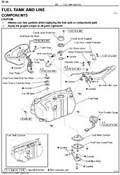
Too bad it is difficult to find good exploded parts diagrams on the parts selling sites anymore. Here is the image from the year 2000 manual. Same image as JPG, PNG, and PDF, depending on what works best. sf - SFI 30.pdf
I recently replaced the pump on my '91, and I unfortunately can't remember whether the sender was integrated with the fuel pump assembly. I think the image from the year 2000 manual clearly shows the sender on the rear face of the tank for the car we're talking about now.
The sender's 300 Ohm potentiometer will be in there somewhere, of course. It looks like if you remove the sender to inspect it, you'll need to be at least below half full. Close to empty would be good.
My doubting of the linearity is based on your initial problem report - that you fill and the gauge reads full, then within 10 miles it is down 1/4 tank. Clearly a problem, and if it does that, I would not assume it drops the remaining 75% on the gauge as the tank drops the remaining 98% of capacity (if it did do that, then a recalibration might work). My guess would be a mechanical problem with the sender, perhaps a film on the resistive surface that could maybe be cleaned off (residue that might increase the resistance over a section of the surface, with the increased resistance resulting in a lower fuel level reading at the gauge).
Often variable resistance devices like this wear out over time. But with the age and very low mileage on this car, I would expect some sort of chemical residue (built up over time while parked) rather than wear.
There are capacitors in the instrument panel as well as the ECU. I know on the earlier years these (in the instrument panel) caused problems, but I don't know if that lasted through 2000. There are also two resistance measurements on the rear of the instrument panel for measuring the circuit that drives the gauge. I'll try to attach those too.
BTW, on terminology here. I would call the thing in the tank with a float the "sender," and the thing in the instrument panel with a needle that moves a "gauge." Lexus literature seems to call these "sender gauge" and "receiver gauge," respectively.
Here is the page (BE-104) from the manual listing the basic electrical tests you can do at the sender connector, as well as the resistance measurements no the back of the instrument panel. As before, in JPG, PNG, and PDF formats. be104.pdf
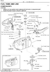
Also, here is a slightly more complete version of the image posted earlier by Yamae. This one includes distance measurements in case you want to be precise about the float location when you take the measurement.
Oldskewel- Thank you so much for these valuable info. I'm currently working on some hot projects at the moment so this fuel gauge's troubleshooting will have to take a backseat for a month or so. I'll report back on my progress & keep you posted.
Yamae- I did some research while waiting for your answer, looks like there are 3 caps in the back of the instrument panel which related to the stuck needles, flickering lights & gauges. Would you please confirm on the qty & the values of these caps. Thanks.
Yamae- I did some research while waiting for your answer, looks like there are 3 caps in the back of the instrument panel which related to the stuck needles, flickering lights & gauges. Would you please confirm on the qty & the values of these caps. Thanks.
Those 3 capacitors are only for 93-94 models. 98-00 models have totally different circuit boards and they have many capacitors but none of them contain the infamous QAS liquid and those don't corrode lead wires. Those seldom leak the liquid but dry up in accordance with the Arrhenius equation. I only have some experience to deal with my JDM instrumental panel which has a fuel gauge at left side as you can see here below. A USDM has it at the right side though. http://celsiorup.com/image/custom20/...ifmoni_215.jpg
The photo below was taken when I removed my cluster unit for the preventative maintenance (PM) long time ago. It shows the area behind the speedometer and the fuel gauge. Most of electrolytic capacitors are located at left side of the photo. There is a 5V voltage regulator indicated "5V regulator" using blue letters by me. This regulator needs bypass capacitors both in and out pins. I don't remember which was for the in but I believe the one next to the regulator is so. I marked " asterisk " to all capacitors in the second photo. The blue one is for the out, I believe. All those capacitors are not QAS capacitors and last longer but those will dry up someday and I dare replaced them all to prevent problems in the future.
As you notice there are 2 blue arrows added by me. Those indicate the terminal for the DC supply to the speedometer and the fuel gauge. Those are connected by a trace and the line is common. This simply means that when the DC supply has some problem, you will have problems both for the speedometer and the fuel gauge. If you have any problem other than the fuel gauge, it would be a good idea to check the DC supply line.
The 3rd photo shows the inverter board for CCFLs. This board is mounted above the meter/gauge board and can be removed easily. This board has 5 electrolytic capacitors which don't contain QAS neither. None of them were defective in my case but I replaced them all too.
I have done the PM job long time ago and I don't have the list of replaced capacitors any more. All of them were still in good conditions except one. The one next to the 5V voltage regulator showed the capacitance 20% less than the value printed. Actually the shrink tube used for was shrank a bit too much.
The fuel gauge on my '98 started playing up about 5 years ago. Now it's totally useless however the fuel computer works perfect so I've never worried about it. In Australia I have been unable to find someone who can fix it so I'm not worried about it at all.
The fuel gauge still 'works' but reads completely inaccurately, but the digital readout is spot on... the temp gauge isn't accurate either so I put another temp gauge in the drivers side door pocket (strange place I know but nowhere else to put it)(It also reads transmission fluid temp) and the tacho reads 1,000rpm too high... other than that, everything on the care works right.... come to think of it, rear window demister works very slowly....
Yours have a digital readout of how much fuel is left in the tank? I've just acquired the 2000, it's still relatively new to me so don't recall of seeing that digital function on mine when I "walked" through all the buttons on the steering wheel. Or do you mean the kilometers you've logged in since your last re-fuel then use that info to estimate how many more kilometers you can go before you run out of gas based on your previous average kilometers/tank?
Yours have a digital readout of how much fuel is left in the tank? I've just acquired the 2000, it's still relatively new to me so don't recall of seeing that digital function on mine when I "walked" through all the buttons on the steering wheel. Or do you mean the kilometers you've logged in since your last re-fuel then use that info to estimate how many more kilometers you can go before you run out of gas based on your previous average kilometers/tank?
I thought the '98 was the same as 2000 model. On my steering wheels there are 3 buttons... function, mode & reset. The function button doesn't do anything, the mode button runs through a bunch of fuel calculations, one of them tells you exactly how many km's left in the tank, av liters per 100km and other stuff. The km's left in the tank resets itself whenever you put fuel in it, its just like a fuel gauge but it just reads km in the tank.
Yamae & Oldskewel- I'm still working on a few hot projects at work so have no time to play w/ the fuel gauge but noticed it is off over the entire range so here's my plan to fix it when I get a chance. Assuming it's linear which is a very good assumption since the fuel gauge is off over the entire range, I can add another potentiometer (Rbias) in parallel w/ the sending unit's 300-Ohm resistor then also connect its center tap to pin B12 (option 1), however by doing so, I'll have a total of 4 resistors (2 from each pots) to play w/ so rather than that, I'll just add the Rbias potentiometer or even a fixed resistor from B12 to ground (option 2). This way, instead of having 4, I'll only have 3 resistors to play w/ so it'll be a bit easier to calculate the value of Rbias & set the bias voltage (either option will work). Since I can't set the fuel level in the tank to be exactly half & also don't want to take a chance of running the tank all the way down to determine the empty level, what I'll do is to fill up the tank at a gas station. Once the fuel pump at the gas station clicked a couple times, I'll considered the tank is full. I'll then check & re-bias the voltage at B12 to 4.38V (I suspect it'll be less than 4.38V prior to the adjustment as it's off). Assuming it's linear, the resistance of the sending unit will increase to 145.8 & 276 Ohms & the fuel gauge voltage will decrease to 2.43V (half full) & .48V (empty), respectively based on the position of the float as the fuel level continues to drop. What do you think?
 04-30-17, 11:21 AM


 sf - SFI 30.pdf
 sf - SFI 30.pdf