


95-97 LS400 Nak stereo LCD replacement tutorial

Thread Starter
Racer


Joined: Mar 2012
Posts: 1,357
Likes: 162
From: or
NOTE: you'll need a donor unit to perform this repair. AFAIK there are no new parts available for these Nakamichi head units. But if you've got a bad unit with a good LCD, and a good unit with a bad LCD, you're ready to go! 
Tools Needed:
small philips screwdriver
any flat pry- tool, not too thick. I used a thin butter knife.
1) Set up your work station. I used a towel on a table for a soft surface to work on. Here's a head unit(slightly blurry):
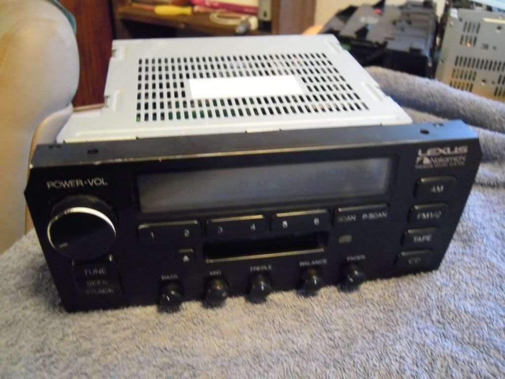
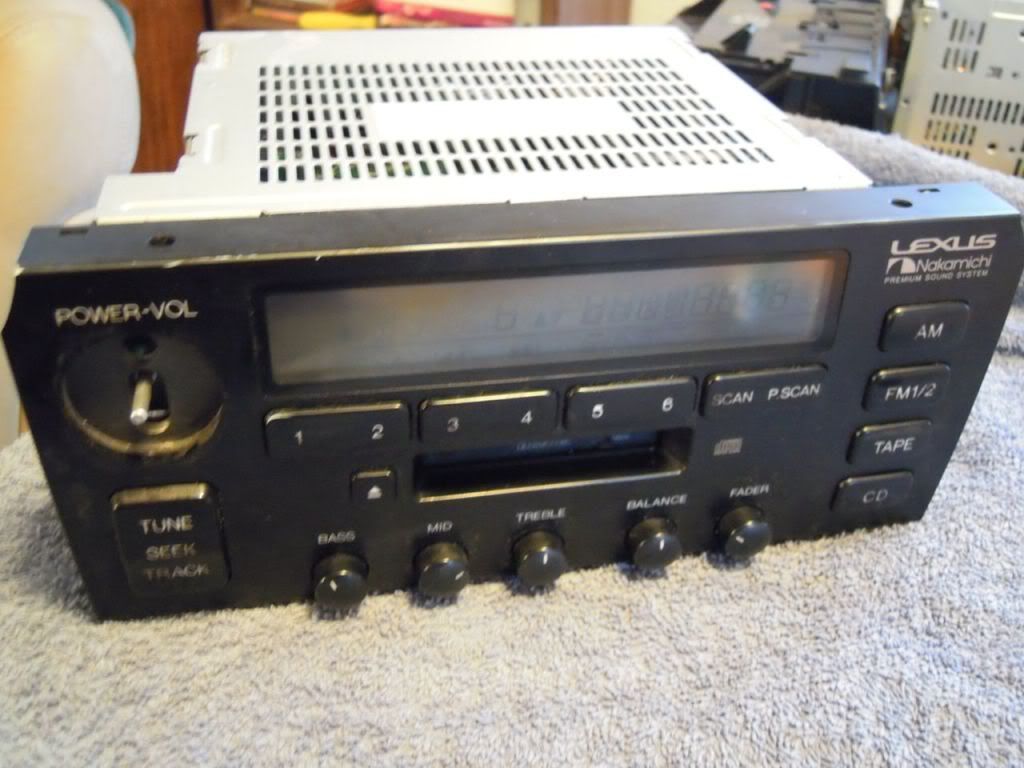
2) Remove the PWR/VOL **** by just grabbing and pulling straight towards you. It should come right off.
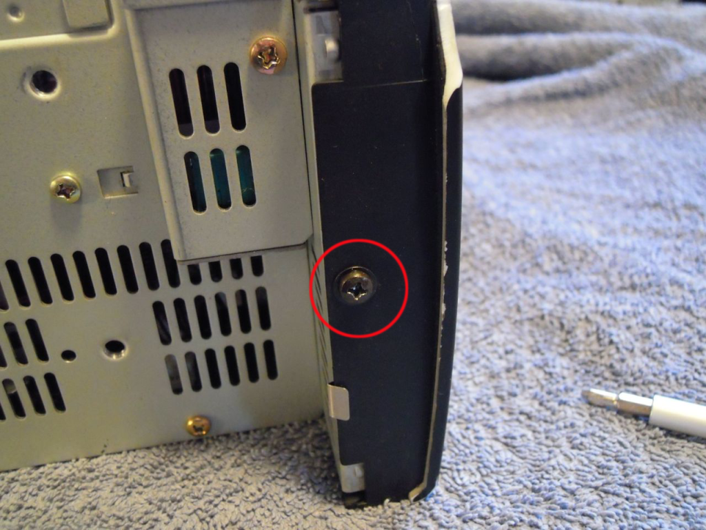
3) On each side of the face, there is a screw(circled in red). Remove both of these.
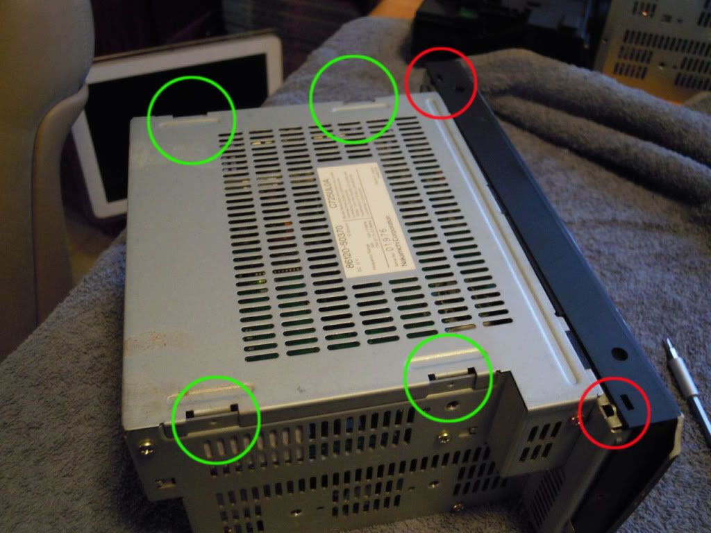
4) Using your flat pry-tool, carefully pop the plastic on the top of the face up over the two little metal tabs(circled in red) that hold it on. This should free up the whole face enough to pull it SLIGHTLY forward. Don't pull far at all, because there are two ribbon connectors inside that connect the face to the body. Next, using your flat pry- tool again, slide it in (horizontally) anywhere around the tabs(circled in green). Gently pry upwards, using a back- and- forth rocking motion, to free the top plate. The whole top plate of the stereo should easily lift off now.
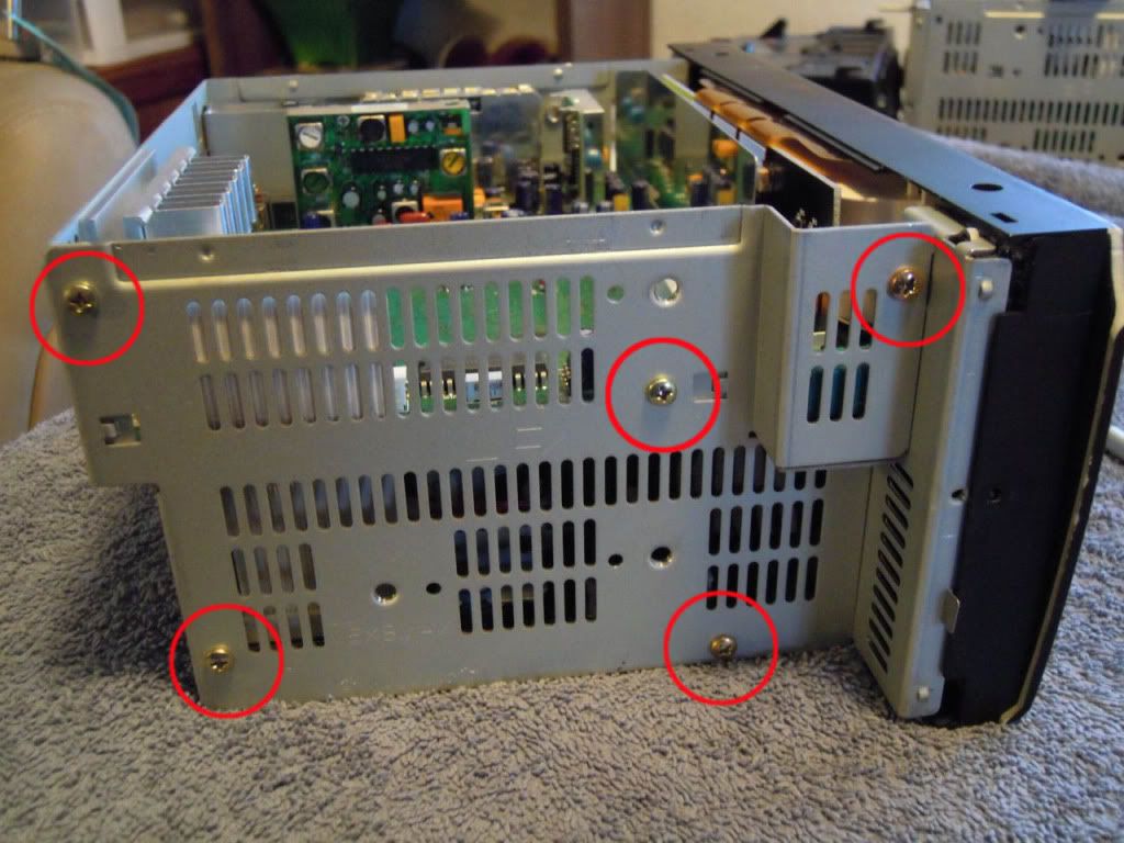
5) Stereo face should be pointing to the right. Remove the 5 screws(circled in red)ONLY ON THIS SIDE. This should free up the whole side plate for removal.
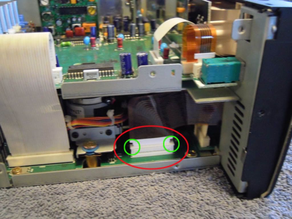
6) This is one of the ribbon connectors(circled in red) that holds the face onto the body. Look closely at how this ribbon plugs into the board. The top of square plastic piece at the base lifts up, which unlocks the ribbon and allows it to be pulled free. Note the circles in green. I just used a fingernail in both of these spots to gently pry the locking mechanism up. Then, using thumb and forefinger, gingerly grab on to the ribbon and pull straight up. It should come free with no effort; if it is stuck, the locking mechanism is probably not all the way up.
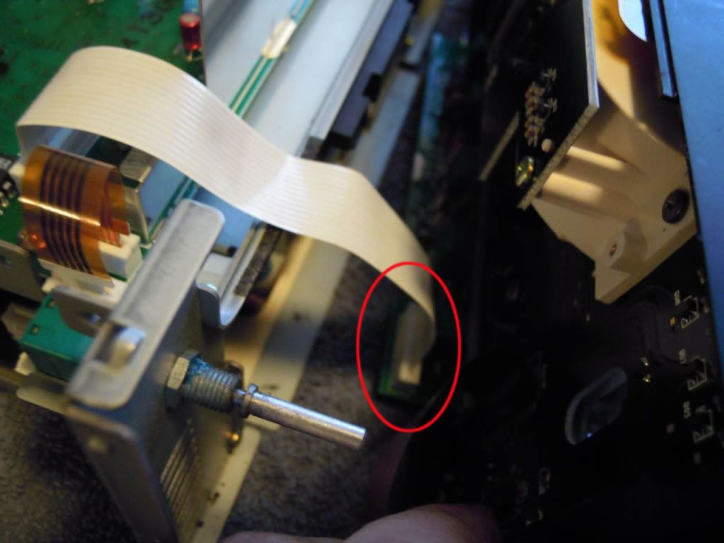
7)Now you will be able to pull the face farther forward. You aren't done removing it yet, so don't get too excited. You may have to pull slightly up and out at the same time to free it. It should come free pretty readily tho, so don't pull too hard. Just carefully work it free. Pull it forward just far enough to give yourself access to the second body/face ribbon connector(circled in red). This plug works the same way as the previous one. I disconnected it on the face- side, but it may also be ok to disconnect it from the body- side.
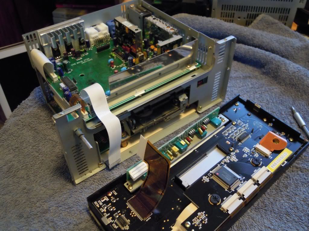
8) Here's what everything should look like now.
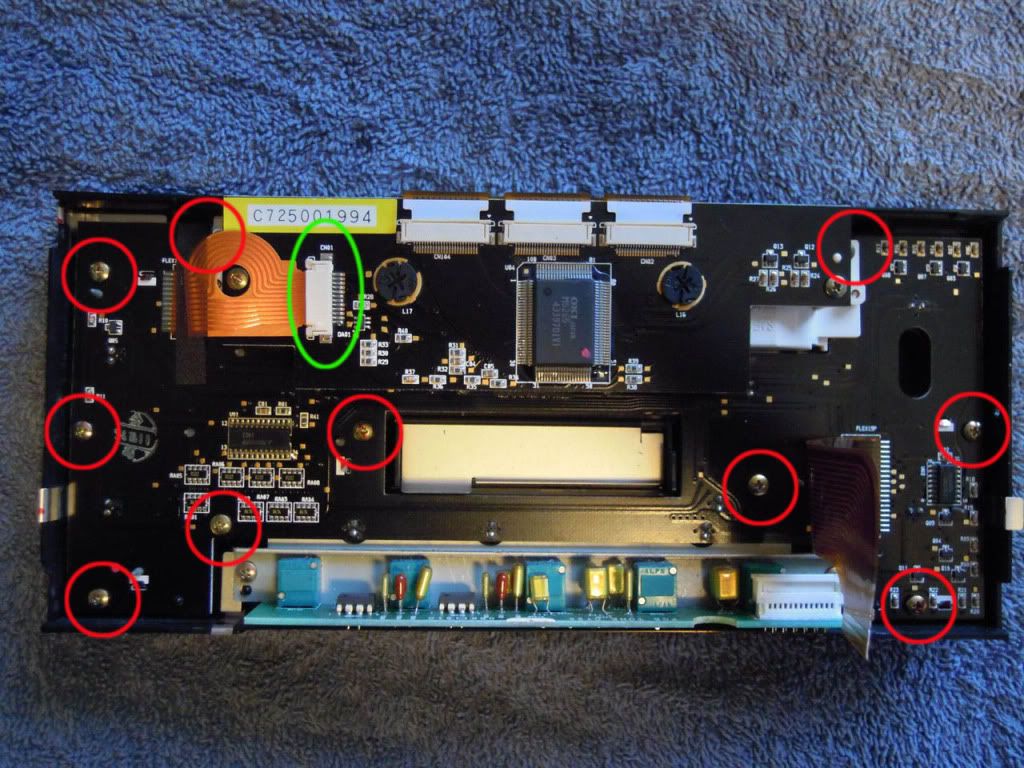
9)Set the face(face down) in front of you, with the top pointing away. There are 10 screws to remove(circled in red). There are two red circles towards the top of the image where you can't see the screws in the pic, but when you are actually working with the unit, you'll see where they are. They mount the LCD unit to the rest of the board. Also, undo the connector circled in green. DON'T remove the two screws that hold the LCD board onto the LCD unit. You should now be able to lift the whole main board/LCD unit up and out of the face. NOTE: Leave the outside face front- down on the towel; if you lift it up or turn it over, there are many buttons that can fall out.
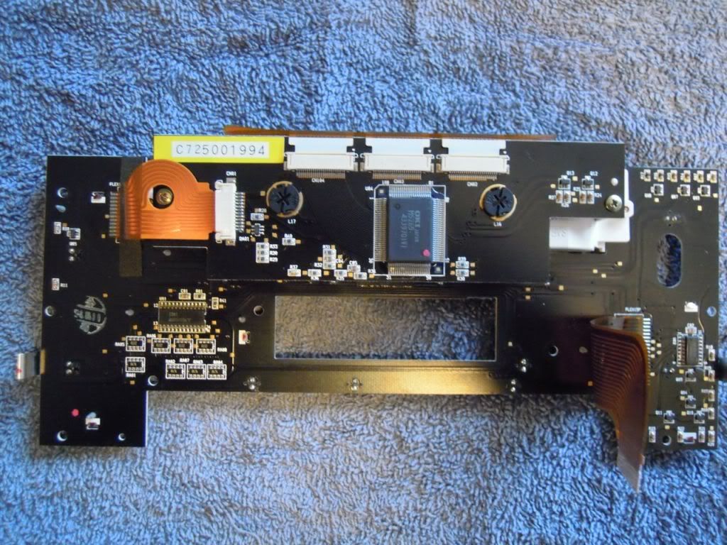
10)This is what the naked board should look like now.
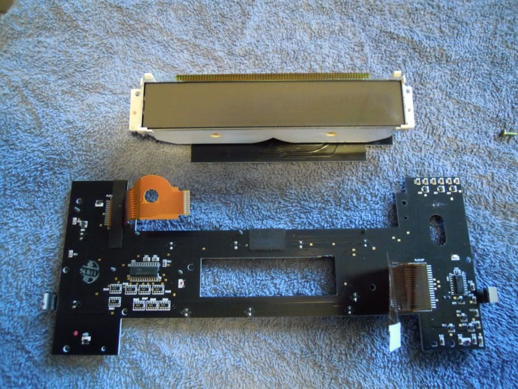
11) The LCD unit should already be free of the rest of the board, just lift it out.
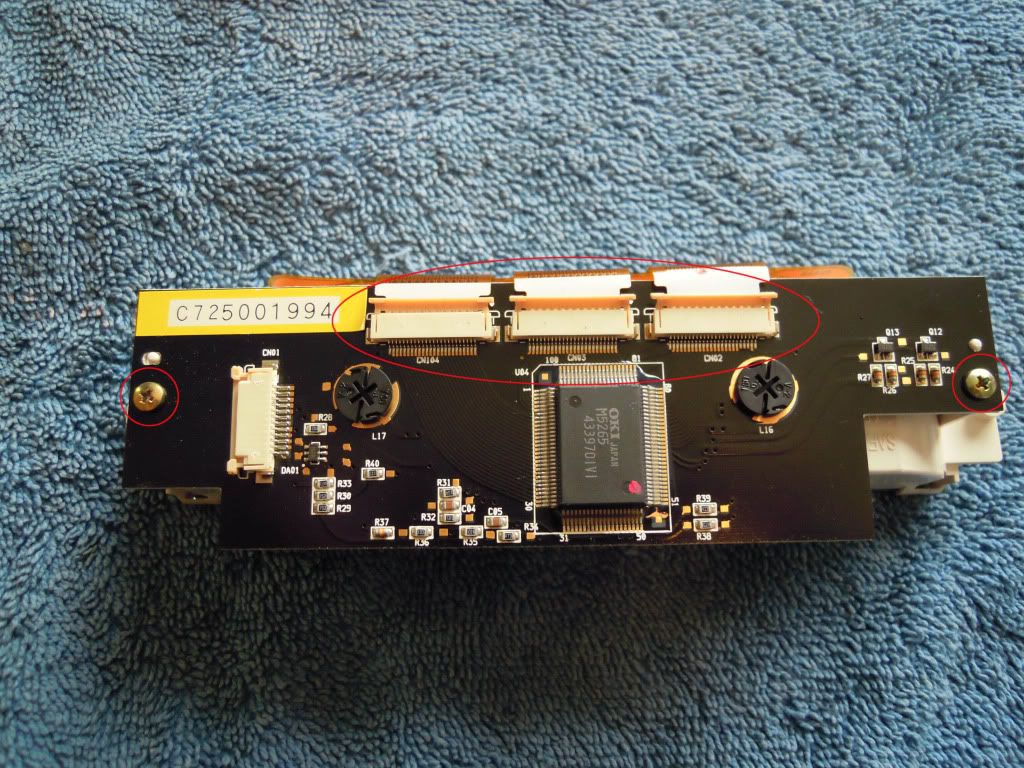
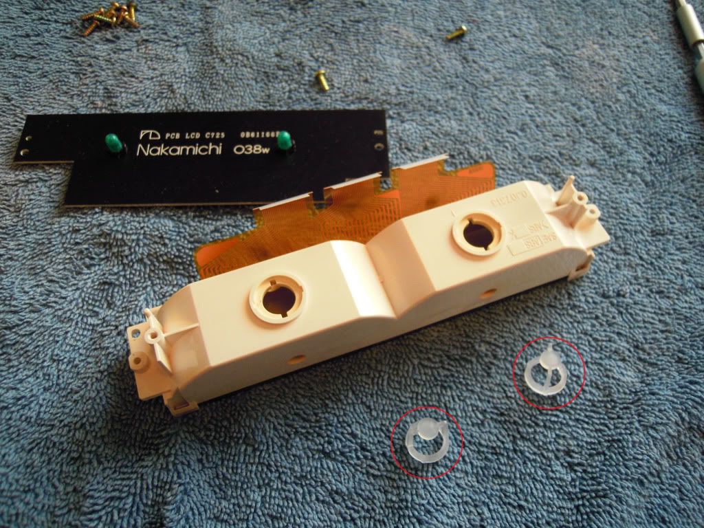
12)You're now down to the LCD unit. If you're just replacing the LCD, and don't need to check/replace bulbs in the LCD unit, ONLY undo the three connectors at the top of the board. Don't worry about removing the two screws(also circled in red) on either side of the board. Then skip to step 14. If you're replacing the bulbs, go ahead and remove those two screws.
13)This is what your LCD unit will look like now, with the board removed. Note the two little white round plastic inserts(circled in red) and don't lose them. They fit in around the bulbs. They do fall out readily, so just be aware of that. Replacement bulbs should be available at Toyota/Lexus.
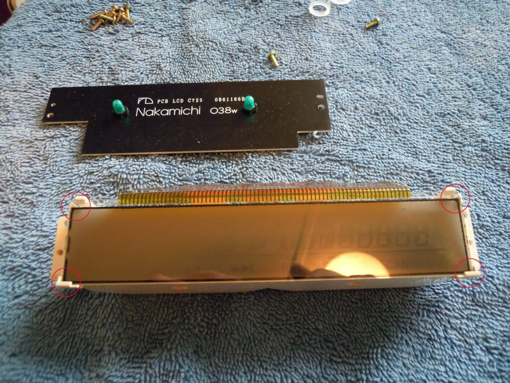
14)You are now ready to remove the LCD. Flip the unit back over, so the LCD is facing you. Note the small clips at each corner(circled in red), which hold the LCD in place. Just use a fingernail to pry these back ever-so- slightly, while gently pulling the LCD up and out of the holder.
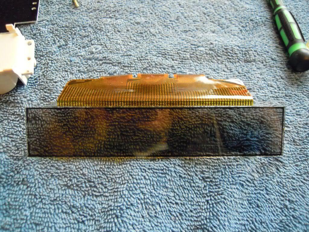
15) This is what the bare-bones LCD looks like. Installation is the reverse of removal. Good luck!
NOTE: I performed this procedure(successfully) a couple of months ago, so everything I wrote is from memory. If you attempt this procedure and find any of these steps to be inaccurate or unnecessary, please reply with your experience! Cheers all!
Tools Needed:
small philips screwdriver
any flat pry- tool, not too thick. I used a thin butter knife.
1) Set up your work station. I used a towel on a table for a soft surface to work on. Here's a head unit(slightly blurry):
2) Remove the PWR/VOL **** by just grabbing and pulling straight towards you. It should come right off.
3) On each side of the face, there is a screw(circled in red). Remove both of these.
4) Using your flat pry-tool, carefully pop the plastic on the top of the face up over the two little metal tabs(circled in red) that hold it on. This should free up the whole face enough to pull it SLIGHTLY forward. Don't pull far at all, because there are two ribbon connectors inside that connect the face to the body. Next, using your flat pry- tool again, slide it in (horizontally) anywhere around the tabs(circled in green). Gently pry upwards, using a back- and- forth rocking motion, to free the top plate. The whole top plate of the stereo should easily lift off now.
5) Stereo face should be pointing to the right. Remove the 5 screws(circled in red)ONLY ON THIS SIDE. This should free up the whole side plate for removal.
6) This is one of the ribbon connectors(circled in red) that holds the face onto the body. Look closely at how this ribbon plugs into the board. The top of square plastic piece at the base lifts up, which unlocks the ribbon and allows it to be pulled free. Note the circles in green. I just used a fingernail in both of these spots to gently pry the locking mechanism up. Then, using thumb and forefinger, gingerly grab on to the ribbon and pull straight up. It should come free with no effort; if it is stuck, the locking mechanism is probably not all the way up.
7)Now you will be able to pull the face farther forward. You aren't done removing it yet, so don't get too excited.
You may have to pull slightly up and out at the same time to free it. It should come free pretty readily tho, so don't pull too hard. Just carefully work it free. Pull it forward just far enough to give yourself access to the second body/face ribbon connector(circled in red). This plug works the same way as the previous one. I disconnected it on the face- side, but it may also be ok to disconnect it from the body- side. 8) Here's what everything should look like now.
9)Set the face(face down) in front of you, with the top pointing away. There are 10 screws to remove(circled in red). There are two red circles towards the top of the image where you can't see the screws in the pic, but when you are actually working with the unit, you'll see where they are. They mount the LCD unit to the rest of the board. Also, undo the connector circled in green. DON'T remove the two screws that hold the LCD board onto the LCD unit. You should now be able to lift the whole main board/LCD unit up and out of the face. NOTE: Leave the outside face front- down on the towel; if you lift it up or turn it over, there are many buttons that can fall out.
10)This is what the naked board should look like now.
11) The LCD unit should already be free of the rest of the board, just lift it out.
12)You're now down to the LCD unit. If you're just replacing the LCD, and don't need to check/replace bulbs in the LCD unit, ONLY undo the three connectors at the top of the board. Don't worry about removing the two screws(also circled in red) on either side of the board. Then skip to step 14. If you're replacing the bulbs, go ahead and remove those two screws.
13)This is what your LCD unit will look like now, with the board removed. Note the two little white round plastic inserts(circled in red) and don't lose them. They fit in around the bulbs. They do fall out readily, so just be aware of that. Replacement bulbs should be available at Toyota/Lexus.
14)You are now ready to remove the LCD. Flip the unit back over, so the LCD is facing you. Note the small clips at each corner(circled in red), which hold the LCD in place. Just use a fingernail to pry these back ever-so- slightly, while gently pulling the LCD up and out of the holder.
15) This is what the bare-bones LCD looks like. Installation is the reverse of removal. Good luck!
NOTE: I performed this procedure(successfully) a couple of months ago, so everything I wrote is from memory. If you attempt this procedure and find any of these steps to be inaccurate or unnecessary, please reply with your experience! Cheers all!
Last edited by mspearl95; Sep 16, 2012 at 08:45 AM.

Rookie
Joined: May 2013
Posts: 83
Likes: 2
From: Florida
Check EBAY actually. I saw a replacement LCD company that sells the LCD screen for the A/C climate control and Clock screen for the LS 400.They may or may not be able to get you one made for the radio. Just a thought.

Driver School Candidate
Joined: Mar 2014
Posts: 2
Likes: 0
From: Canada , BC
Thanks ! This helped me to fix my problem with '95 ls400 . My right side speakers were cutting off 95% of the time, I had a music only on left side speakers  .I followed this and I did re-soldering balance potentiometer and now is working in STEREO again Thank you!!!!!!!
.I followed this and I did re-soldering balance potentiometer and now is working in STEREO again Thank you!!!!!!!
Trending Topics
ClubLexus Stories
Celebrating Lexus & Toyota from Around the Globe

Lexus NX 350h: A Fuel-Sipping Secret Hot Hatch???
Michael S. Palmer
5 Best & 5 Worst Lexus Daily Drivers
Joe Kucinski
Top 5 Hottest Lexus & Toyotas in 2026 (Hardest To Buy)
Brett Foote
2026 Lexus IS 350 F Sport Review: The Last of Its Kind Still Rocks
Michael S. Palmer
Top 10 Most Confusing Things Lexus Has Ever Done!
Joe Kucinski
2026 Lexus ES Review: Lexus Re-Embraces Founding Principles
Michael S. Palmer
10 Lexus Bargains That are Cheaper Than a New Toyota RAV4
Joe Kucinski
8 Weirdest Things Lexus Has Ever Built
Verdad Gallardo
10 Lexus Designs That Have Aged Like Fine Wine
Verdad Gallardo
If I went through all this I would definitely upgrade all the illumination to LEDs. I recently did a similar job when replacing my climate control module. Once I had the new one I took it apart and replaced the 12 "green" standard bulbs with white LEDs and it made a big difference in brightness and looks.
Sponsor
Joined: May 2012
Posts: 1,140
Likes: 156
From: WI
Doubtful, unless there is a demand for 100's of these replacement LCDs.
__________________
TANIN AUTO ELECTRONIX
262-456-4147
contact@taninauto.com
www.taninautoelectronix.com
https://taninjdm.com/ Our Lexus LS430 Dealership

TANIN AUTO ELECTRONIX
262-456-4147
contact@taninauto.com
www.taninautoelectronix.com
https://taninjdm.com/ Our Lexus LS430 Dealership


Driver School Candidate
Joined: Sep 2015
Posts: 3
Likes: 0
From: Switzerland

8th Gear
Joined: Jun 2024
Posts: 8
Likes: 0
NOTE: you'll need a donor unit to perform this repair. AFAIK there are no new parts available for these Nakamichi head units. But if you've got a bad unit with a good LCD, and a good unit with a bad LCD, you're ready to go!
Tools Needed:
small philips screwdriver
any flat pry- tool, not too thick. I used a thin butter knife.
1) Set up your work station. I used a towel on a table for a soft surface to work on. Here's a head unit(slightly blurry):

2) Remove the PWR/VOL **** by just grabbing and pulling straight towards you. It should come right off.

3) On each side of the face, there is a screw(circled in red). Remove both of these.

4) Using your flat pry-tool, carefully pop the plastic on the top of the face up over the two little metal tabs(circled in red) that hold it on. This should free up the whole face enough to pull it SLIGHTLY forward. Don't pull far at all, because there are two ribbon connectors inside that connect the face to the body. Next, using your flat pry- tool again, slide it in (horizontally) anywhere around the tabs(circled in green). Gently pry upwards, using a back- and- forth rocking motion, to free the top plate. The whole top plate of the stereo should easily lift off now.

5) Stereo face should be pointing to the right. Remove the 5 screws(circled in red)ONLY ON THIS SIDE. This should free up the whole side plate for removal.

6) This is one of the ribbon connectors(circled in red) that holds the face onto the body. Look closely at how this ribbon plugs into the board. The top of square plastic piece at the base lifts up, which unlocks the ribbon and allows it to be pulled free. Note the circles in green. I just used a fingernail in both of these spots to gently pry the locking mechanism up. Then, using thumb and forefinger, gingerly grab on to the ribbon and pull straight up. It should come free with no effort; if it is stuck, the locking mechanism is probably not all the way up.

7)Now you will be able to pull the face farther forward. You aren't done removing it yet, so don't get too excited. You may have to pull slightly up and out at the same time to free it. It should come free pretty readily tho, so don't pull too hard. Just carefully work it free. Pull it forward just far enough to give yourself access to the second body/face ribbon connector(circled in red). This plug works the same way as the previous one. I disconnected it on the face- side, but it may also be ok to disconnect it from the body- side.

8) Here's what everything should look like now.

9)Set the face(face down) in front of you, with the top pointing away. There are 10 screws to remove(circled in red). There are two red circles towards the top of the image where you can't see the screws in the pic, but when you are actually working with the unit, you'll see where they are. They mount the LCD unit to the rest of the board. Also, undo the connector circled in green. DON'T remove the two screws that hold the LCD board onto the LCD unit. You should now be able to lift the whole main board/LCD unit up and out of the face. NOTE: Leave the outside face front- down on the towel; if you lift it up or turn it over, there are many buttons that can fall out.

10)This is what the naked board should look like now.

11) The LCD unit should already be free of the rest of the board, just lift it out.

12)You're now down to the LCD unit. If you're just replacing the LCD, and don't need to check/replace bulbs in the LCD unit, ONLY undo the three connectors at the top of the board. Don't worry about removing the two screws(also circled in red) on either side of the board. Then skip to step 14. If you're replacing the bulbs, go ahead and remove those two screws.

13)This is what your LCD unit will look like now, with the board removed. Note the two little white round plastic inserts(circled in red) and don't lose them. They fit in around the bulbs. They do fall out readily, so just be aware of that. Replacement bulbs should be available at Toyota/Lexus.

14)You are now ready to remove the LCD. Flip the unit back over, so the LCD is facing you. Note the small clips at each corner(circled in red), which hold the LCD in place. Just use a fingernail to pry these back ever-so- slightly, while gently pulling the LCD up and out of the holder.

15) This is what the bare-bones LCD looks like. Installation is the reverse of removal. Good luck!

NOTE: I performed this procedure(successfully) a couple of months ago, so everything I wrote is from memory. If you attempt this procedure and find any of these steps to be inaccurate or unnecessary, please reply with your experience! Cheers all!
Tools Needed:
small philips screwdriver
any flat pry- tool, not too thick. I used a thin butter knife.
1) Set up your work station. I used a towel on a table for a soft surface to work on. Here's a head unit(slightly blurry):
2) Remove the PWR/VOL **** by just grabbing and pulling straight towards you. It should come right off.
3) On each side of the face, there is a screw(circled in red). Remove both of these.
4) Using your flat pry-tool, carefully pop the plastic on the top of the face up over the two little metal tabs(circled in red) that hold it on. This should free up the whole face enough to pull it SLIGHTLY forward. Don't pull far at all, because there are two ribbon connectors inside that connect the face to the body. Next, using your flat pry- tool again, slide it in (horizontally) anywhere around the tabs(circled in green). Gently pry upwards, using a back- and- forth rocking motion, to free the top plate. The whole top plate of the stereo should easily lift off now.
5) Stereo face should be pointing to the right. Remove the 5 screws(circled in red)ONLY ON THIS SIDE. This should free up the whole side plate for removal.
6) This is one of the ribbon connectors(circled in red) that holds the face onto the body. Look closely at how this ribbon plugs into the board. The top of square plastic piece at the base lifts up, which unlocks the ribbon and allows it to be pulled free. Note the circles in green. I just used a fingernail in both of these spots to gently pry the locking mechanism up. Then, using thumb and forefinger, gingerly grab on to the ribbon and pull straight up. It should come free with no effort; if it is stuck, the locking mechanism is probably not all the way up.
7)Now you will be able to pull the face farther forward. You aren't done removing it yet, so don't get too excited.
You may have to pull slightly up and out at the same time to free it. It should come free pretty readily tho, so don't pull too hard. Just carefully work it free. Pull it forward just far enough to give yourself access to the second body/face ribbon connector(circled in red). This plug works the same way as the previous one. I disconnected it on the face- side, but it may also be ok to disconnect it from the body- side.8) Here's what everything should look like now.
9)Set the face(face down) in front of you, with the top pointing away. There are 10 screws to remove(circled in red). There are two red circles towards the top of the image where you can't see the screws in the pic, but when you are actually working with the unit, you'll see where they are. They mount the LCD unit to the rest of the board. Also, undo the connector circled in green. DON'T remove the two screws that hold the LCD board onto the LCD unit. You should now be able to lift the whole main board/LCD unit up and out of the face. NOTE: Leave the outside face front- down on the towel; if you lift it up or turn it over, there are many buttons that can fall out.
10)This is what the naked board should look like now.
11) The LCD unit should already be free of the rest of the board, just lift it out.
12)You're now down to the LCD unit. If you're just replacing the LCD, and don't need to check/replace bulbs in the LCD unit, ONLY undo the three connectors at the top of the board. Don't worry about removing the two screws(also circled in red) on either side of the board. Then skip to step 14. If you're replacing the bulbs, go ahead and remove those two screws.
13)This is what your LCD unit will look like now, with the board removed. Note the two little white round plastic inserts(circled in red) and don't lose them. They fit in around the bulbs. They do fall out readily, so just be aware of that. Replacement bulbs should be available at Toyota/Lexus.
14)You are now ready to remove the LCD. Flip the unit back over, so the LCD is facing you. Note the small clips at each corner(circled in red), which hold the LCD in place. Just use a fingernail to pry these back ever-so- slightly, while gently pulling the LCD up and out of the holder.
15) This is what the bare-bones LCD looks like. Installation is the reverse of removal. Good luck!
NOTE: I performed this procedure(successfully) a couple of months ago, so everything I wrote is from memory. If you attempt this procedure and find any of these steps to be inaccurate or unnecessary, please reply with your experience! Cheers all!

Thread
Thread Starter
Forum
Replies
Last Post
mspearl95
LS - 1st and 2nd Gen (1990-2000)
5
Apr 2, 2012 07:31 AM
ucfjon
LS460 / 430 / 400 / 600h Classifieds
3
Jun 25, 2011 03:11 PM