When you click on links to various merchants on this site and make a purchase, this can result in this site earning a commission. Affiliate programs and affiliations include, but are not limited to, the eBay Partner Network.
In the diagram below you would have to cut the red wire at the Body ECU connector and wire it to an Ignition ON source...then they would be on whenever the vehicle is on.
Text sent.
The Main Body ECU in located on the lower left side of the drivers dash area....you'll need to take off the lower dash panel.
Look for connector 4B pin 11 as per the diagram below. The Main Body ECU has multiple connectors on different sides. First confirm you are looking at the view with the two connectors below, then look for the red wire on the upper connector...I circled pin 11 in red.
I would rather find the pinout for the ambient lighting in the car, so that the footwells can be wired up to dimmer LED's than the footwell uses to light up for entry. Do you have the info for the ambient lighting pin?
Text sent.
The Main Body ECU in located on the lower left side of the drivers dash area....you'll need to take off the lower dash panel.
Look for connector 4B pin 11 as per the diagram below. The Main Body ECU has multiple connectors on different sides. First confirm you are looking at the view with the two connectors below, then look for the red wire on the upper connector...I circled pin 11 in red.
Brilliant. So take that wire at pin 11 from that connector, cut, and connect to ignition ON source. Where might I find the ignition ON source to connect to?
Not positive I'll do this if it's not dimmed but could fix that.
Thanks Sasnuke.
I would rather find the pinout for the ambient lighting in the car, so that the footwells can be wired up to dimmer LED's than the footwell uses to light up for entry. Do you have the info for the ambient lighting pin?
Brilliant. So take that wire at pin 11 from that connector, cut, and connect to ignition ON source. Where might I find the ignition ON source to connect to?
Not positive I'll do this if it's not dimmed but could fix that.
Thanks Sasnuke.
I'm looking at the 2014 350 wiring diagrams to see if there is a better way to do this.
After a little more research, those two bulbs in pic up above are switched power and ground from the Body ECU...so it would be best to take them out of the control of the Body ECU and make a dimmer circuit out of them.
In the diagram below you would have to cut the red wire at the Body ECU connector and wire it to an Ignition ON source...then they would be on whenever the vehicle is on.
don’t mean to bring this old post back, but can you look for the 2014 GS350? I’d love to have my ambient always full bright!
don’t mean to bring this old post back, but can you look for the 2014 GS350? I’d love to have my ambient always full bright!
Thanks!
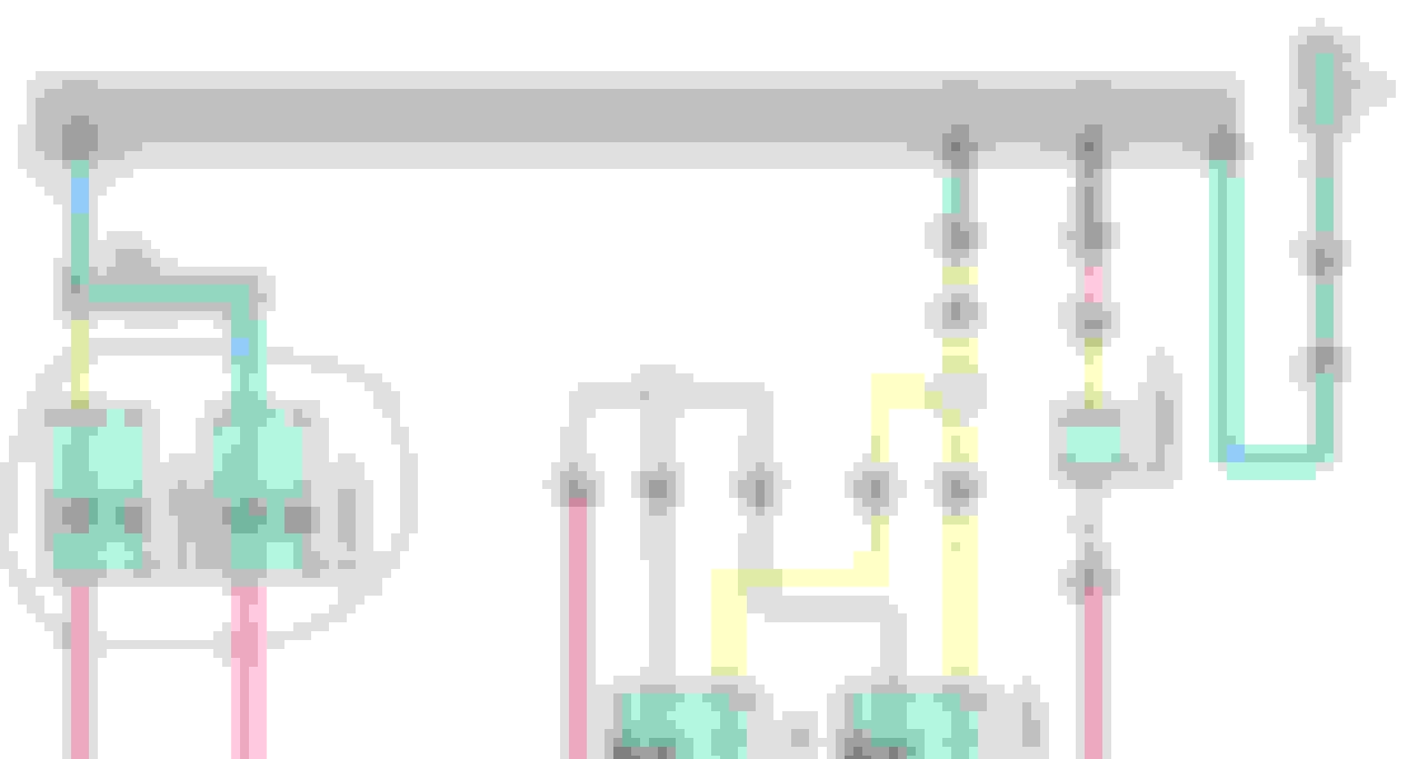
Here's the diagram for the '14 GS350...the lights are supplied power from the Light Blue wire, and the Red wires go to the Body ECU which switches the Ground side to turn them on.
Depending on how you want them to work will depend on how you modify the wiring.
1. Lights on whenever vehicle is running (night or day) - disconnect the Light Blue wire at connector 4A pin 33 and connect it to an Ignition on power source. Then disconnect the Red wires and route them directly to Ground. So whenever the car is Ignition On, or Engine On, the lights will be on.
2. Turn the lights on whenever you want, regardless if the vehicle is on - disconnect the Red wires, join them together, and connect them to one side of a manual switch (you need to get a switch). Connect the other side of the switch to Ground. In this setup you can turn the lights on/off whenever you want...and the vehicle doesn't have to be running. The downside is that you could forget to turn them off when you leave the vehicle and accidentally discharge the battery.
I could think of at least one more way to connect them...but it really depends on what you want.
Here's the diagram for the '14 GS350...the lights are supplied power from the Light Blue wire, and the Red wires go to the Body ECU which switches the Ground side to turn them on.
Depending on how you want them to work will depend on how you modify the wiring.
1. Lights on whenever vehicle is running (night or day) - disconnect the Light Blue wire at connector 4A pin 33 and connect it to an Ignition on power source. Then disconnect the Red wires and route them directly to Ground. So whenever the car is Ignition On, or Engine On, the lights will be on.
2. Turn the lights on whenever you want, regardless if the vehicle is on - disconnect the Red wires, join them together, and connect them to one side of a manual switch (you need to get a switch). Connect the other side of the switch to Ground. In this setup you can turn the lights on/off whenever you want...and the vehicle doesn't have to be running. The downside is that you could forget to turn them off when you leave the vehicle and accidentally discharge the battery.
I could think of at least one more way to connect them...but it really depends on what you want.
nice! Now what about the ambient lighting on the door? If I feed pin 1 on q29 with constant 12V, will it always stay on or it’s not that simple? Lol
nice! Now what about the ambient lighting on the door? If I feed pin 1 on q29 with constant 12V, will it always stay on or it’s not that simple? Lol
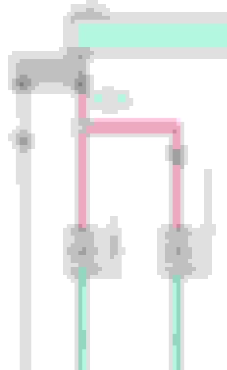
The pink wire should have a constant 12V, and the ECU will simply switch the Ground side (SB blue wire) when it wants to turn the light on.
You would need to confirm that when the door is closed, and the vehicle is off, if the pink wire has 12V...if it does, then if you Ground the blue wire to the chassis the light will be on all the time...like ALL the time.
You would need to disconnect the blue wire from the ECU and run it to a switch that the other side of the switch is connected to Ground. Then you can turn the lights on and off at will.
When I say "disconnect" I mean either remove the pin from the connector (if you have the tools and nohow) or cut the wire, about an inch from the connector so you could always reconnect it if you like.
The pink wire should have a constant 12V, and the ECU will simply switch the Ground side (SB blue wire) when it wants to turn the light on.
You would need to confirm that when the door is closed, and the vehicle is off, if the pink wire has 12V...if it does, then if you Ground the blue wire to the chassis the light will be on all the time...like ALL the time.
You would need to disconnect the blue wire from the ECU and run it to a switch that the other side of the switch is connected to Ground. Then you can turn the lights on and off at will.
When I say "disconnect" I mean either remove the pin from the connector (if you have the tools and nohow) or cut the wire, about an inch from the connector so you could always reconnect it if you like.