When you click on links to various merchants on this site and make a purchase, this can result in this site earning a commission. Affiliate programs and affiliations include, but are not limited to, the eBay Partner Network.
With the test light connects at the two end of the fuse, can it functions as a fuse insert?
What do you mean?
In this case it will limit current flow equal to the wattage of the incandescent lamp.
An example is this:
A 55watt lamp ran at 12v draws -> 55w/12v = 4.6 Amps
That said a tiny test lamp like that might produce 0.25 watts. 0.25w/12.8v = 0.019Amps (19mA). Which isn't enough energy to do anything but drain your battery over the course of a week.
Give me some detail but it won't run your amplifier if that is what you are asking.
What you need to do now is with that plug unplugged from the amp but powered, determine which wires are Ground and Supply 12V battery power, then use your ohm meter to probe the amps pins that correspond to Ground and +12V. If those pins show zero ohms i.e. a dead short then you have confirmed the power supply into the amp is shorted and killing your fuse.
That said open the amp and trace the 12v power and ground until you find the blown up component which is likely a shorted protection diode. It may be burned and charred or look perfectly fine. But your ohm meter and diode check meter will find it guilty when placed across the anode and cathode. i.e. shorted. Mind you we are talking about a 0.39cent part here that can be replaced.
I wanted to use the test light to replace a fuse in order to confirm the amp is still working but that did not work. The test light limited the electric current so the amp did not get enough power. I got it now
Just want to clarify if I understand your instruction correctly. Assume that I already know which ground pin and power input pin on the amplifier. Now, using the multimeter, one lead connect to the ground pin and the other lead connect to the power input pin of the amplifier to measure the ohm? 0 ohms meaning short.
I will open the case to inspect the components inside the amp if there is a short.
Thanks for the explaination again, 2013FSport! Learn something every day
You could be OK here. The battery lead reversal usually blows up a component (protection diode) right at the input. That said yes, ohm pwr and gnd, if shorted (ohms less than 10) open the amp and take pictures.
Some call this a clamp diode but basically during polarity reversal this diode shorts the input blowing the fuse upstream and saves the amp by shorting out at $2.00 component.
Replace the diode and it is a very good chance everything works again.
Hang in there...
Here is what I found:
Power and ground pins on the amplifier
Ohms reading between the pins 0.5 Ohms, please note that I set the meter to 200, not sure if that is correct???:
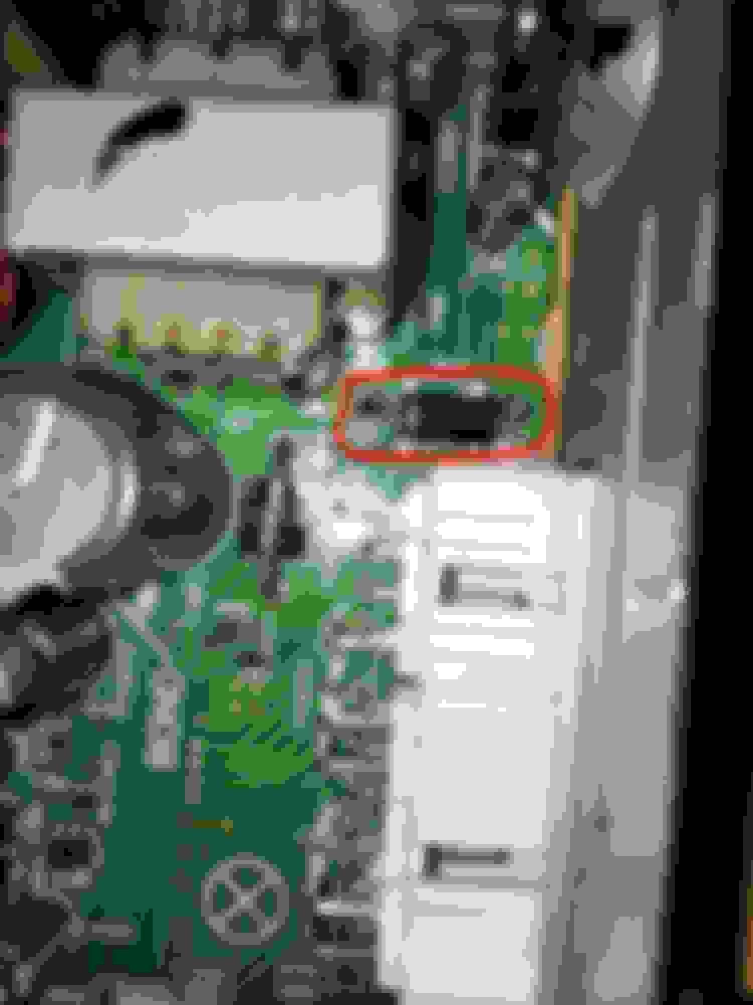
Here is the inside of the amp. There is a broken diode:
another picture taken from a different angle:
Meter reading on diode #1 (the broken one):
Meter reading from diode #2. Please note the negative#, does not matter which side switch between the red and black leads, it always give the same negative value.
Please look at the pictures and let me know if you see any unusual that I need to check/replace. Thank you in advance!
Diode #2 although not blown in half is a dead short and taking out your fuse. Diode #1 although physically compromised shows a good value at .53....
So both of those diodes connect to +12 and gnd?? Looks like it.
You ever solder anything?
Do they both appear to have the same ### etched in them?
Go to digikey.com put in the letter/number combination and post up the specs for what you find.
From the production date you should use lead free solder and soldering tips. Because both of those are into the power grid so to speak the copper there is thick and wide and displace your heat rapidly.
It will take a a higher power soldering iron to quickly remove those and not overheat the PCBA below them. You do not want to burn the fiberglass board or the copper traces will lift ruin the pcba.
See the other components on the PCBA that look the same but are smaller (diodes). Place your leads on those, get a reading in both diode mode and ohms, then reverse the leads and repeat the test. You should see infinite ohms one way and 0.5 or .7 ohms the other. Voltage tests in diode mode will by higher.
Identify and order parts. We'll work on replacement as need be.
PS - cut the leads on ONE side of each diode and ohm the input. Reverse polarity and repeat. You may need to move from the 200 scale to a higher scale but the ohms should jump up substantially once the shorted diode is cut at one leg. Let us know what you find.
Maybe find the thanks button too! =,)
Last edited by 2013FSport; Sep 20, 2018 at 03:12 PM.
Diode #2 although not blown in half is a dead short and taking out your fuse. Diode #1 although physically compromised shows a good value at .53....
So both of those diodes connect to +12 and gnd?? Looks like it.
You ever solder anything?
Do they both appear to have the same ### etched in them?
Go to digikey.com put in the letter/number combination and post up the specs for what you find.
From the production date you should use lead free solder and soldering tips. Because both of those are into the power grid so to speak the copper there is thick and wide and displace your heat rapidly.
It will take a a higher power soldering iron to quickly remove those and not overheat the PCBA below them. You do not want to burn the fiberglass board or the copper traces will lift ruin the pcba.
See the other components on the PCBA that look the same but are smaller (diodes). Place your leads on those, get a reading in both diode mode and ohms, then reverse the leads and repeat the test. You should see infinite ohms one way and 0.5 or .7 ohms the other. Voltage tests in diode mode will by higher.
Identify and order parts. We'll work on replacement as need be.
PS - cut the leads on ONE side of each diode and ohm the input. Reverse polarity and repeat. You may need to move from the 200 scale to a higher scale but the ohms should jump up substantially once the shorted diode is cut at one leg. Let us know what you find.
Maybe find the thanks button too! =,)
So both of those diodes connect to +12 and gnd?? I forgot to mention that there are 2 pairs of wires coming from two power sources (RAD NO. 1 and RAD NO. 2) and the they both connect to the same connector. The orange/white-black (bottom) wires connect to RAD NO.2 fuse and the red/white-black(top) connect to RAD NO. 1 fuse. So look like each diode is used by each pair of power source. Both diodes are the same model RM4.
You ever solder anything? Yes, I did solder something in the past with a cheap soldering iron, does not work well, I have to look for a better one. I will have to practice with it a bit
I have to return the digital multimeter to my friend today. (mine stopped working 2 weeks ago) I placed an order on amazon for a new multimeter. I will have to buy another soldering iron tool cause mine is power enough to melt the lead of the diode. This project is put on hold until I get the tools. I will get back on this hopefully in a few days
NP... so did you by chance ohm the input swapping lead direction after cutting the leads? This is FTW if the ohms shot up!
It looks like the batch from amazoo has a keeper in there. That said something special about that RM4 diode is its speed or ability to react quickly and stop the in rush of reverse current.
It should work but the other factor is the leakage current. That said it likely doesn't matter as it's only on when requested unlike some of the electronics that sit idle drawing a tiny bit of current always.
I'm not going to say do it, but as long as the polarity is not reversed you *could* plug it in and test it. Without protection the amp could be fried if the polarity is reversed....
Sorry I removed the cutting diode from the board two days ago without measuring the ohm before my digital multimeter got home.
Anyway, the diodes got home today and I soldered it in (only the bad one), my soldering skill is really bad . But it fixed the issue. My car's amplifier is back in business now.
diode part#1N5404:
Replaced only the failed diode:
Again thanks everyone for helping me fixing my car, especially thanks to 2013FSport for walking me through the process of troubleshooting the issue on the amplifier
Last edited by test_accou; Sep 23, 2018 at 07:27 PM.
[QUOTE=test_accou;10316114]Je remplacerai celui cass� s'il tombe en panne � l'avenir [/QUOTE
]bonjour je voudrais savoir si ava t cela vous aviez du courant contact mis?car sur ma is 250 avec le conta t ca mar he et une fois demarrer pas de son.le courant arrive bien jusqu'a l'ampli et fusible ok