When you click on links to various merchants on this site and make a purchase, this can result in this site earning a commission. Affiliate programs and affiliations include, but are not limited to, the eBay Partner Network.
Thanks to Acrad for inspiring me to do this instead of another switch swap, in addition to answering my many questions related to the mod. I was ready to order a combo switch assy and he asked about using simple switches. I mentioned it would be easier for me to just order the part like everyone else had done. He considered all those people who wouldn't be able to or want to order the combo switch assy and convinced me that this should be a project.
Risks were many, here's a few I had to consider.
Fry a computer, destroy a harness, melt something with the soldering iron, ruin something during the calibration, drill something off center, and so on.
Consider that in the cold there's more static, and a discharge could ruin a number of things. The soldering iron could leak a current through the wire.
And even after complete, a wire could wear through if rubbing, a switch could go bad.
If you attempt this, understand that there's risk. and it's your risk. ALL YOURS. Mitigate the risks as needed. My risks are not necessarily the same as yours. My skills are not the same or at the same level.
This mod has 2 main sets of steps and outcomes.
1 - adding Crawl Control (CC) by adding 3 switches and performing a cal. THis is all thats needed for CC to function.
2 - adding illumination to the 3 switches by connecting the switch LEDs to the OEM dimmer. this was for looks and a little ease find in the dark.
This mod could have been done at either end of the harness that connects the driving support computer to the combo switch assy. I was already working in the driving support computer area so I used that end of the harness. If only adding CC then working at the combo switch assy end of the harness could have been quicker and easier.
I could have used any momentary switches and any wire for this mod.
Without getting much into steps covered elsewhere:
I installed CC on my ’12 premium using simple switches instead of installing the CC combo switch assy.
Here's the parts I used and what I did, along with some other info that could be useful.
It is strongly recommended to disconnect the battery when doing work on the electronics. I did not disconnect the battery. This doesn't mean anyone should ever do what I did. Disconnecting or not disconnecting both have risk, My risk assessment for my situation caused me to not disconnect the battery.
OK enough about risk.
Parts I used.
CC on/off switch
1 of 19mm momentary push button switch with green LED (12v). Flat/flush button face.
1 of 50k ohm resistor for the 12v LEDs to match the OEM brightness.
CC speed up/down switches
2 of 12mm momentary push button switch with LED (3v). Raised button face.
2 of 107k ohm resistors for the 3v LEDs to not burn from the 12v and to match OEM brightness
Wire
6 ft or so of 4 conductor wire, I used Belden 8723
I removed passenger side parts to be able to access the driving support computer harness.
On the drivers side I removed parts to be able to pass the wire through and removed the center diff switch panel.
I fished the belden through from the drivers side to the passengers side, by taping the belden to a wiper rail
Next I located the driving support computer and disconnected the connector. Wires were bent/curved.
The left 4 OEM harness wires on the backside of the connector at the driving computer were used.
Position 16 white/black is ground
Position 15 black is CC on/off
Position 14 green is CC speed down
Position 13 blue is CC speed up
If I had been working at the combo switch assy end of the harness I would have used these
Position 9 white/black is ground
Position 6 black is CC on/off
Position 3 green is CC speed down
Position 5 blue is CC speed up
I cut the wire protector tape at the end closest to the connector and separated the 4 wires used
I cut different distances from the connector to prevent one big clump of wire solder joints. The bent wires would need to go back to bent for strain spread/relief.
Wire colors should be the same at either the driving support computer end or the combo switch assy harness end.
I cut the belden staggered lengths, similar but opposite of the OEM so that they would all line up.
This mod added switches to one end of the harness, it did not permanently disconnect any wire. I chose the driving computer side although I could have chosen the combo switch assy side.
Insulated butt splice wire connectors were an option. T-Tap wire connectors were not an option. T-Tap are never an option for multiple reasons. I chose solder.
Belden foil and shield wire not used and cut off. Also had put a heat shrink piece over the belden cut edge.
I put the wire protector back in place and added 3 cable ties. One for protector retention and 2 for harness retention, cable ties in order to avoid tape adhesive issues later.
yes i did cut off the ends later
I left the connecter disconnected until all soldering, including switches, was done. I did not reconnect the connector to the computer at this point. This protected the computer while working on the other end of the wire and the switches.
I wanted the switches near the center diff lock button. Second place option was 3 of 7mm switches near the USB port.
The bigger the switches the more difficult the install when placing switches where I placed them.
Using 3 of 7mm non-illuminated non-labeled round switches would have been much easier. The 7mm switches mount from the back, same side as the wires so theyre easier to solder then place than most others that mount through the front and then get soldered in.
I chose round for ease of cutting and orientation. I wanted illuminated for night visibility.
The 1 19mm and 2 12mms were a tight fit, not even 1 mm margin for error.
I did try some flat/flush button 12mms but they were difficult to press/activate and not possible with gloves.
Heres the nut for the 19mm. close fit. used tape for marking and alignment.
I also placed the 2 12 nuts to check for clearance at the same time (not shown). Nuts needed to turn without hitting anything.
Used a dremel and cutoff wheel to cut off a little plastic to flush for the 19mm (cut shown) and the bottom 12mm (cut not shown)
I mounted the 3 switches. I did not use the o-rings.
Each momentary switch has 2 terminals used for this mod control portion
Wire fished again same technique
At this time I soldered as much as possible at the workbench to reduce install time in the vehicle.
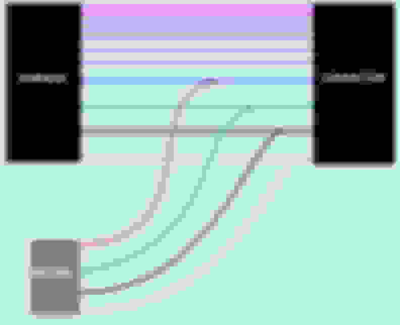
If i had not wanted LED switch illumination I would have connected the switches like shown in the diagram above, put it all back together and did a calibration.
CC would have worked.
-----------------------------
Actually it did because i made a test box early on using smaller non illuminated switches.
Then calibrated, (pushed CC ON/Off before final cal exit), then was done
This disabled the DAC functionality and caused the DAC switch to no longer activate DAC.
Early test setup showing 1 12mm round mounted square switch and 2 7mm in an electrical box
That earlier post showed the steps to get CC, those were the easier steps especially when I used the test switch box.
Here are the steps for illumination tied to the OEM dimmer. This was more difficult than the previous posts steps.
I did the measuring for the switches, drilling and much of the soldering to the switches at the bench.
Here are also pics showing the tight tolerances and the wiring involved, and the final results.
Illumination not required in order for CC to work
I added illumination tied to OEM dimmer.
This was only possible because of the small current draw of the LEDs in my switches. Did not and would not try with incandescents.
In general, the OEM dimmer goes to many of the white LEDs on switches, displays, etc.
Usually OEM dimmer does not tie to the colored LEDs such as in the dash for headlights, parking sensor, or yellow LED indicators on switches such as heated steering, seat heater, etc. I originally planned to use white, and still do plan to go back to white once the parts arrive, so I tied to the OEM dimmer. Also the LEDs for all 3 are brighter than I like, so even if not tied to the dimmer I would have added resistors in addition to whatever would normally be called out for the LEDs.
I used left over wire for the illumination add.
Center diff switch harness connector has 10 positions. Harness section has 4 wires.
wires used
Position 8 green OEM is ILL+
Position 7 gray OEM is ILL-
The 12mm switch LED needed resistors to not burn out the LED at 12v. The 19mm did not need a resistor for use at 12v.
I added high value resistors to all 3 in order to tie in to the OEM brightness control and to make the LEDs in the switches I added have similar brightness to the OEM switch LEDs in the area.
I tapped into the center diff lock harness using the same steps as before for the driving support computer harness
I soldered as much as possible at the workbench to reduce install time in the vehicle.
I used about 10 inch wires on the diff lock and belden connection points on the switch panel to be connected once in the vehicle.
Then I connected the final few wires (2 center diff lock wires and 4 belden wires) inside the vehicle.
The center diff lock harness was retained further in the dash area and I did not look for the retention point.
This meant that there was not a lot of extra wire to work with.
I put everything back in place.
ON/OFF is green
UP/DOWN are blue.
I plan to go to white once the parts arrive, and if they match the OEM white on the center diff lock switch. The original 2 12mm white I received were not the same white. My OEM engine start white also does not match the two white below it, but the 12mm I received were unacceptably different.
This switch is 8mm, has a raised button and LED. current ALI price 2$ shipped
8mm is the mount hole diameter
This would be much easier especially if just tying the LED to 12v and not the OEM dimmer. still needs a resistor. almost all 12mm or less in this style need an external resistor.
so the day i post about almost all small LED switches needing external resistors I receive in the mail a 12mm white LED switch that already has the resistor built in.
it is becoming more common that the manufacturers put the resistor inside.
here's a 12mm white led with internal resistor. its marked for the operating voltage of the LED
this one might not even need any external resistor as it appeared dimmer than the other ones i used.
Earlier I showed a mod to use simple switches to add CC. Some might want simpler.
Here is the other end of the spectrum. Complexity, benefit, cost, logistics, detail, time and risk are reduced. No waiting for parts, no visible change, maybe 15 mins to complete.
How to convert the DAC switch to a CC switch.
once at the harness connector at the combo switch assy:
1 disconnect it and cut the CC ON/OFF wire position 6 BLK and cut the DAC ON wire position 15 LT GRN making sure to leave enough wire to reconnect.
2 connect the connector end DAC 15 LT GRN wire to the harness end CC BLK 6 wire. At this point there is a cut BLK wire at the connector, and also a cut LT GRN wire at the harness. These are not used and can be secured.
Now the switch is converted. still need to run the cal process to get the computer to control the CC properly.
operation after cal completion
to turn on CC, flip the DAC switch to on and then back off. It doesnt matter how long you take since the signal works on the flip on only. CC works at the medium speed.
to turn CC off, flip the DAC switch to on and then back off. It doesnt matter how long you take since the signal works on the flip on only. CC stops working.
You the man, great job! Curious how much money this saves over ordering the OEM switches?
the oem switch is about 400$ most places. once in a while its cheaper, sometimes from the middle east
the 12mm switches i used for up/down are 1.50$
the 19mm about 2$
the 7mm in the test setup are 0.15$ thats 15 cents
I added another switch option and when i get chance ill show some other places i considered for adding switches if I had decided I didnt want them next to the diff lock switch and I was only working in the combo switch assy area.
what i put above for the lights might seem difficult. now that there are many 12mm 12v LED switches available this mod gets much easier by just connecting everything at the combo switch assy. no resistors needed and can either connect to the dim or not without diggin in at the center diff lock.
and the lights arent really needed for CC.
when i first learned about CC way back, due to my ignorance i was not impressed and didnt think it even worth the time to do for free. I wanted MTS. then i looked more into CC and how I use my GX and potential situations where I would need one of the systems. then i started looking into CC, learned more about it, and realized I wanted both.
for a feature that might not get used, the combo assy switch could be too expensive, but the simple switch method is for sure affordable.
maybe someone will add some simple switches at the combo switch assy and post their pics.
How many hours did this take? you can knock out the parts swap in 2 hours and you have to believe your time is worth something, so did you really save any money?
How many hours did this take? you can knock out the parts swap in 2 hours and you have to believe your time is worth something, so did you really save any money?
I�m not the OP, but I would assume that most of the extra time he spent for this mod was based on the research, planning and the write up for the forums benefit. Someone installing this following his guide would probably save a good amount of time and $. Some people like tinkering and doing things a different way. That�s what makes this group great.
I agree and that's not an unreasonable point, but I would also be carful doing this mod if your vehicle is still under warranty, as one look at that hack by the dealer and they will be doing everything in their power to say the factory warranty is now void....JMHO
IMO... probably best to wait until warranty is expired as well. The stock switch and ECU do seem to fly under the radar if warranty is a concern.
Originally Posted by shmelvin1
I agree and that's not an unreasonable point, but I would also be carful doing this mod if your vehicle is still under warranty, as one look at that hack by the dealer and they will be doing everything in their power to say the factory warranty is now void....JMHO
How many hours did this take? you can knock out the parts swap in 2 hours and you have to believe your time is worth something, so did you really save any money?
My guess is it would take a couple of hours following what I wrote. I was doing a lot of other stuff mixed in there at the same time so I dont have an accurate estimate for just the switch add.
I dont compare the value in $ of my time to projects and I didnt do this to save money. It was for the community and those who dont want to spend on the combo switch assy, or who need to use that combo switch assy area for something else yet still want CC. I am sure others have looked into this, and maybe some even thought they could do it, but they didn't want to take the risk because they weren't confident enough in their skills. I have enough confidence to not worry about damaging anything, and I know enough to be able to show that I wouldnt damage anything if I was worried about warranty. I also add enough other goodies to my cars that I know space can be limited and more options are better.