When you click on links to various merchants on this site and make a purchase, this can result in this site earning a commission. Affiliate programs and affiliations include, but are not limited to, the eBay Partner Network.
Ok, I am still diagnosing stuff on my no-start issue.
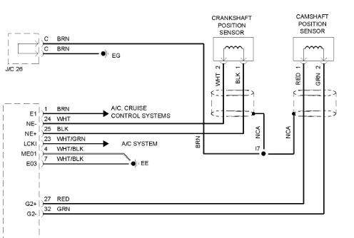
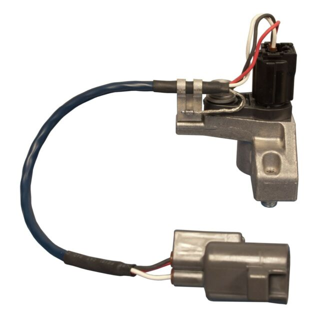
I am now diagnosing the CAM sensor. I am a tad baffled. The wiring diagram shows two wires connecting to the actual sensor, but a new sensor (with mount) shows 4 wires at the sensor. Three of them go into sensor connector, and one looks like a bare shield.
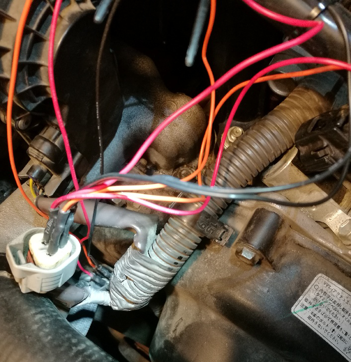
If I disconnect the cam sensor connector (right behind the radiator hose) and try to start it, ECM does not throw a DTC. <---- odd.
But, wiring diagram shows it a bit different. The diagram shows only two wires sensor side. So what's that 3rd wire for? Is the wiring diagrams in Sticky accurate diagrams?
Using ohm meter on sensor pins only (switching meter leads on every pin set, etc). Is this a good or bad sensor?
White+ Green- = 0ohm
White- Green+ = 754ohm
Green+ Red- = 451ohm
Green- Red+ = 1126ohm
White+ Red- = 0ohm
White- Red+ = 1892ohm
What the heck is going on there? If it's just a coil pickup the resistance should be the same both ways. If there's a diode in there (and I don't know why there would be) then the values are whack.
Check the battery in your voltmeter? Get a good multimeter?
I have Fluke and Southwire DVM's, the meters are a-ok.
I am not sure what's up with these CAM sensors. Wiring diagram shows a 2-wire sensor, but the actual sensor has 3 wires. I am thinking they are powered Hall sensors and not basic coil sensors. I am thinking ECM G2+(red) is a ref voltage (like 5v from a linear regulator), G2-(green) is the signal from sensor, and guessing the 3rd wire is the gnd. I will probe to see.
From the schematic. It seems to be two wire sensor. The third wire is shieling wire and tired to ground (EG) through a jumper connector J/C 26.
Did you measure it with the connector on or off?
From the schematic. It seems to be two wire sensor. The third wire is shieling wire and tired to ground (EG) through a jumper connector J/C 26.
Did you measure it with the connector on or off?
Harness connector to sensor connector was disconnected, I then probed the pins in the sensor connector, etc. If one of the sensor wires is a shield wire then why do I have ohms between each pair combo? A shield wire would be infinite ohms between the other wires (should be), etc.
The schematic only shows a single connector, supposedly that's the one between harness and the connector that hangs on cam gear cover just behind the radiator hose. But look at the cam sensor pic, why is there a 3rd wire in the sensor, schematic only shows two, not three, etc. I don't even see a brown wire harness side.
I'm gonna pull some docs from TIS on Monday. I bet ya these 3-wire sensors are Hall sensors, and not passive shielded reluctor sensor.
The cam sensor is a Denso MRE type (two MRE's in the sensor). It's a powered sensor that outputs square wave via transistor final "signal" stage.
From doing some digging, these MRE sensors appear to be pull-up type. From what I can see, the sensor has a final open-collector stage transistor (npn) with a resistor to the collector as a small load at the sensor. The "signal" wire to the ECM connects to the sensor transistor collector and when the sensor turns 'on' that transistor the "signal" wire (green) becomes chassis ground (zero volts). I will scope this to see if my sensor is good or bad.
In my same digging I see lots of mention of Toyota switching to MRE sensors in 2006 for V8 UZ-FE. Need to find some history on this.
I suspect my cam sensor is toast, but will do some testing.
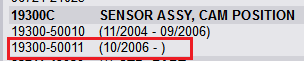
Why the wiring diagram shows a 2-wire reluctor type is a tad baffling to me. Update: Well, the baffling part is now explained. The wiring diagram in the Sticky's must be 2003-2004 GX470 (PDF properties show author date of Jan 2005). In looking up parts for a 2004 GX470 I see two part #'s, the one in red box is a 2-wire sensor (2003 & 2004 GX's), the other is a 3-wire (starting with the 2005 model year). I think I have the years correct based on the dates from parts list.
And I see here it looks like they changed the sensor for 2007 model years. This new one is about $25 more than the other (Toy price). What's the diff I don't know. These part #'s are the assembly, not just the sensor, so it could be new sensor, or it could just be a new mount for 2007. .
Yeah, you need to look up parts by the VIN if you think they superseded it at some point, because Toyota made tons of small mid-year changes to the GX470 over its life
Well, as of today, my post #7 is not correct.
Today I find, via TIS docs, that the green-black wire is a 5v reference voltage. There is no wire on the sensor that goes directly to body ground.
And scoping between G2+ and G2- wires I do not find any good square wave, nor any decent looking signal at all, yet I did Noid light #5 and it is blinking.
Made some break-out patch wires so I could probe w/o stabbing wires, etc. I don't see any square wave during starting, this suggests to me a faulty cam sensor. But I did get some spark when Noid light on #5, but it flashed 3x during my 3/4 start (I off the key before letting starter go full start cycle, etc). I don't think the crank rotates 6x during that brief start time.
 10-16-20, 03:15 PM


 .
.