
DIY: Adding a volt meter next to clock

Lead Lap
Joined: May 2015
Posts: 449
Likes: 49
From: Illinois
If anyone else does this mod recently, please post some pictures and give a link of where you got it. I want to get a green led for my Lexus but I would like for it to be as close in color as the OEM green clock is.

Rookie


Joined: Jul 2008
Posts: 86
Likes: 1
From: FL
Going to try and install mine this weekend. Got mine off Amazon. They also have different selection of colors.
DROK 0.28" LED Ultra-small DC Digital 0~~~~100V Voltmeter Battery Voltage Tester Green Display Car Motorcycle Panel Meter 3.0-30 Power Volt Detector Gauge~~~
https://www.amazon.com/dp/B00C58QIOM?ref=yo_pop_ma_swf
DROK 0.28" LED Ultra-small DC Digital 0~~~~100V Voltmeter Battery Voltage Tester Green Display Car Motorcycle Panel Meter 3.0-30 Power Volt Detector Gauge~~~
https://www.amazon.com/dp/B00C58QIOM?ref=yo_pop_ma_swf

I started doing this mod, and want to confirm a few things before I do something stupid.
Did you separated the very front dark/clear plastic from the frame, and then cut an opening in the frame for the voltmeter? Did you drill out the six glued attach points first?
And how did you mount the voltmeter to the housing? Glue?
Did you separated the very front dark/clear plastic from the frame, and then cut an opening in the frame for the voltmeter? Did you drill out the six glued attach points first?
And how did you mount the voltmeter to the housing? Glue?
Mounted with black hot glue.
Hope this helps u.

Advanced


Joined: Dec 2005
Posts: 550
Likes: 25
From: ca
As for wiring the voltmeter, did you use all three wires as shown by OP, or did you tie two of the wires together?
Advanced
Joined: Dec 2005
Posts: 550
Likes: 25
From: ca
Going to try and install mine this weekend. Got mine off Amazon. They also have different selection of colors.
DROK 0.28" LED Ultra-small DC Digital 0~~~~100V Voltmeter Battery Voltage Tester Green Display Car Motorcycle Panel Meter 3.0-30 Power Volt Detector Gauge~~~
https://www.amazon.com/dp/B00C58QIOM?ref=yo_pop_ma_swf
DROK 0.28" LED Ultra-small DC Digital 0~~~~100V Voltmeter Battery Voltage Tester Green Display Car Motorcycle Panel Meter 3.0-30 Power Volt Detector Gauge~~~
https://www.amazon.com/dp/B00C58QIOM?ref=yo_pop_ma_swf
Advanced
Joined: Dec 2005
Posts: 550
Likes: 25
From: ca
Just finished my mod, super happy with the results. Great job OP!
A few tips for the first timers. I didn't take photos during disassembly, but the reassembly should hopefully identify all the important steps.
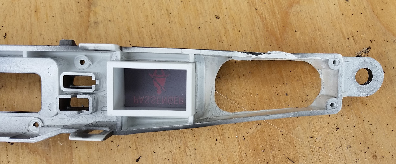
To pull the assembly out, simply pry at the whole HVAC vent assembly and pull. There are two connectors behind, disconnect them:
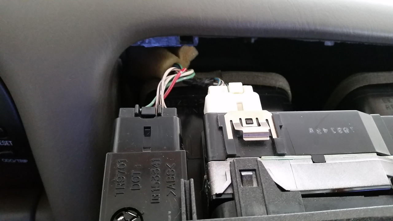
Then separate the clock assembly from the HVAC panel (one 10mm head screw, and some tabs).
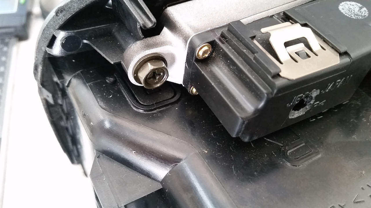
Then separate the front and back housings from each other (tabs and three small Phillips screws).
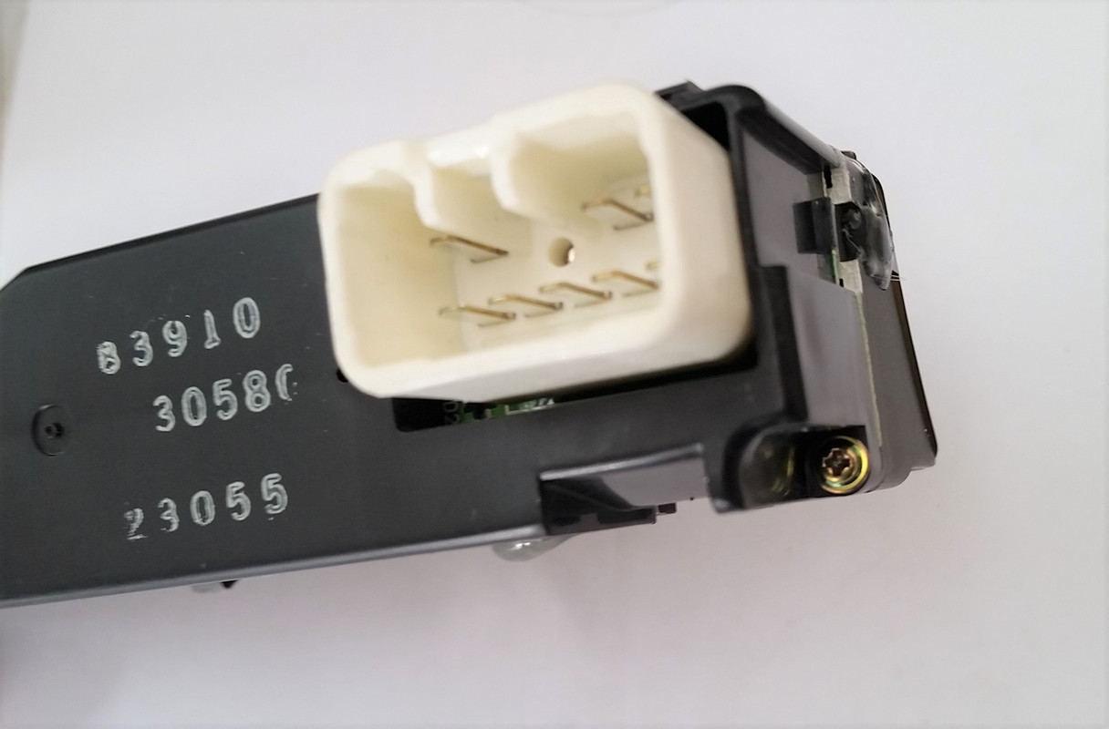
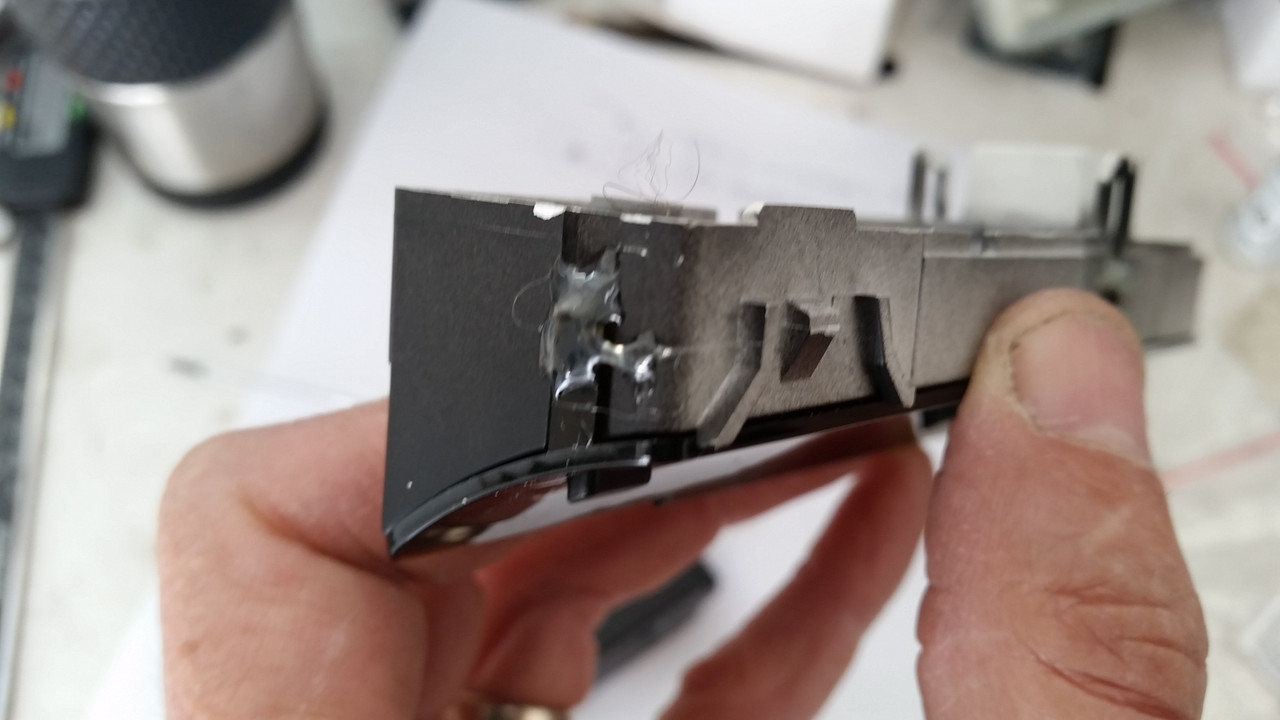
Now you need to remove the "glass" (dark plastic really) by either dremeling or breaking off the six plastic posts. Also remove the circuit board from the housing by removing four small Phillips screws.
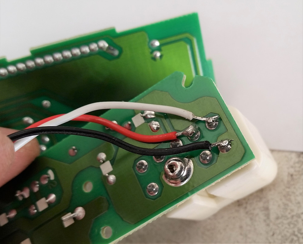
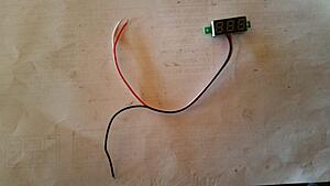
Now everything is apart. You need to solder the voltmeter leads to the three posts as shown by OP. My wire colors were different, but the functions the same. Black is ground, Red is constant 12V, White is 12V voltage triggered by the ignition key (you want to use this one, or else your voltmeter will always be on). Here are the posts to use:
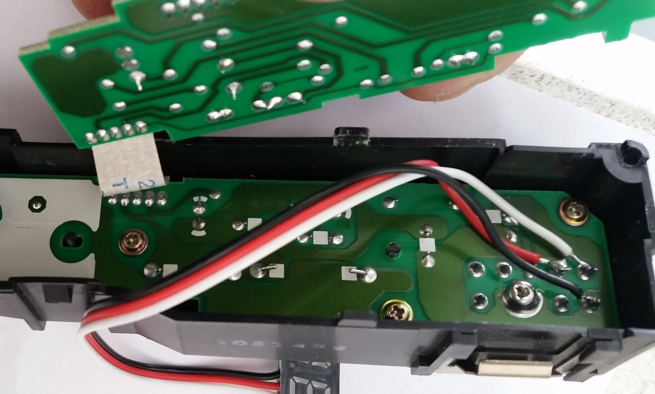
Put the circuit board back in and reinstall the four screws:
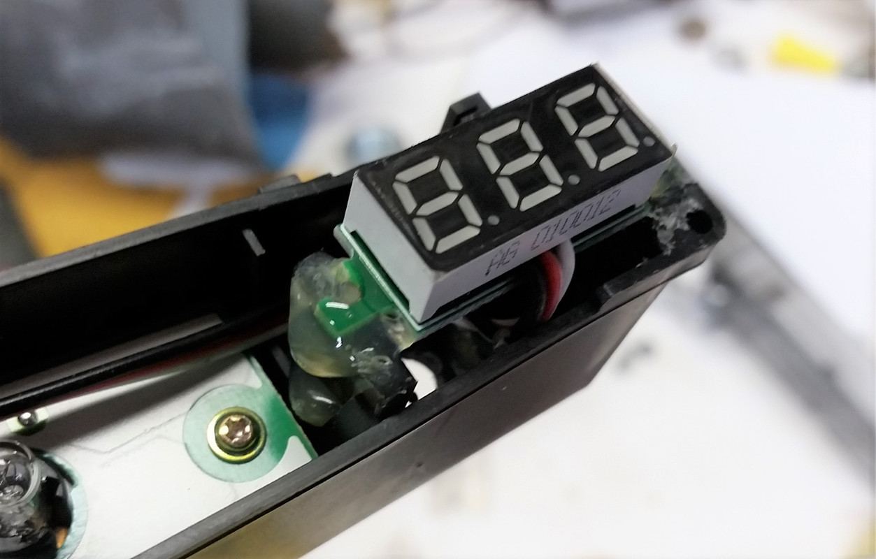
Decide where you want to place the voltmeter and come up with a support system. I ended up gluing two pieces of plastic to act as supports, then glued the voltmeter tabs to these supports:
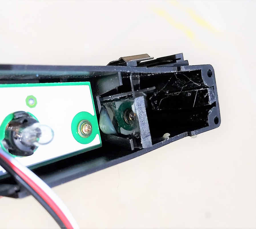
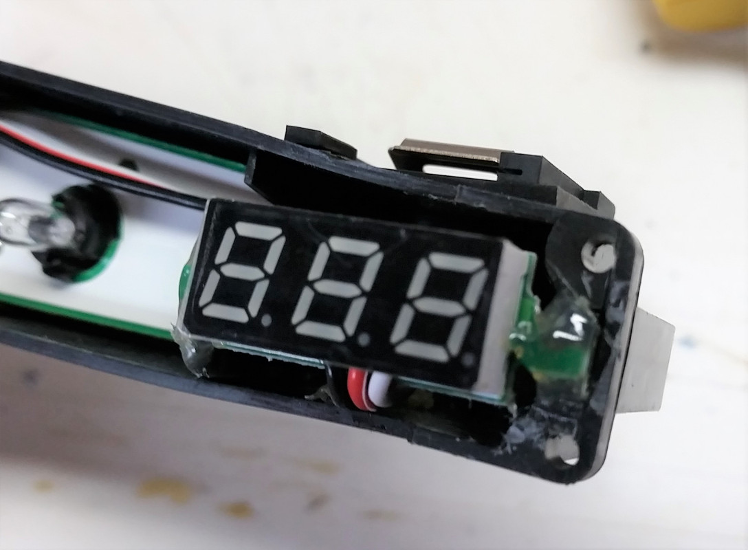

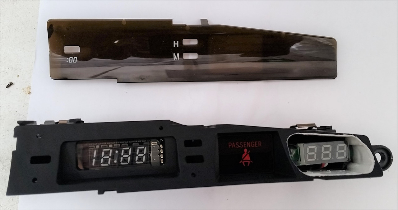
Now you need to cut an opening in the front of the clock housing for the voltmeter to show through. I made the opening as big as possible to maximize view angles:

Now you can snap the front housing back over the circuit board housing (the photo below is just a test fit, you can see that the buttons for the clock functions are not in place. They need to be reinstalled before reassembling the housings):

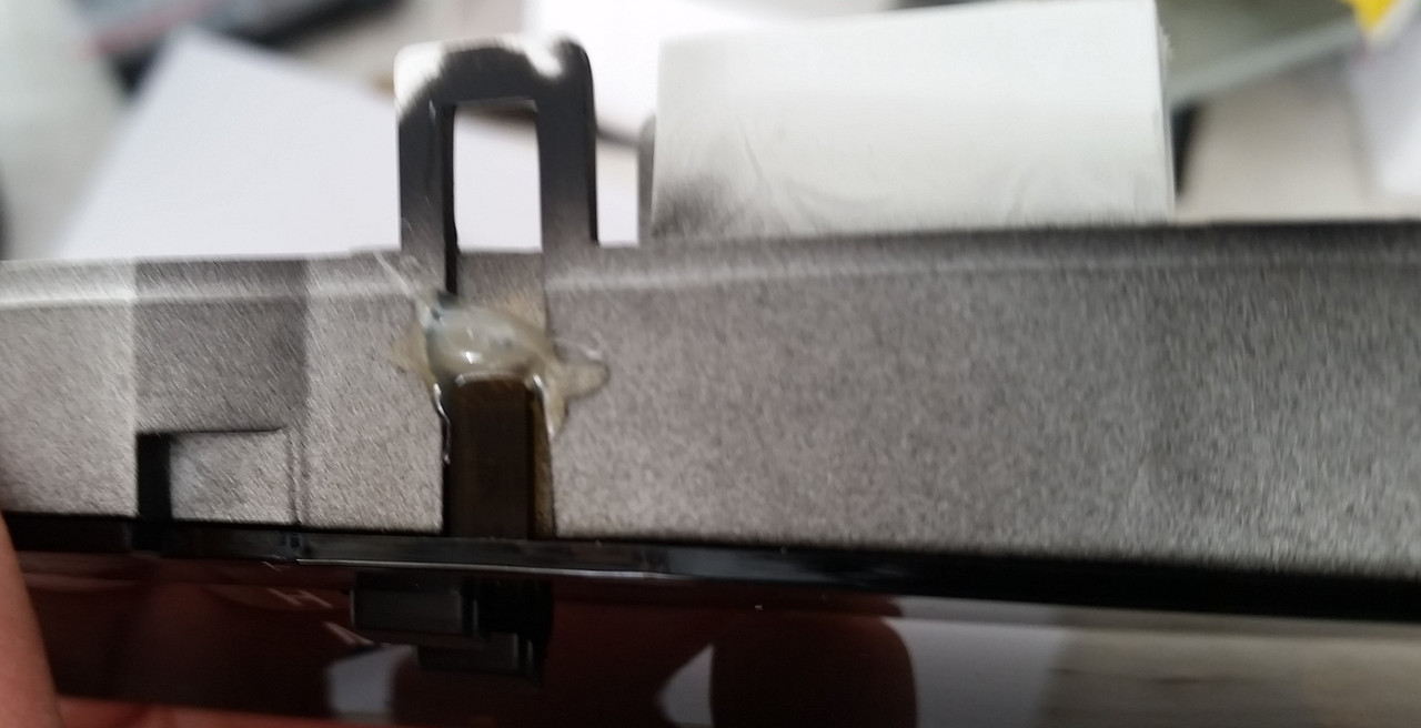
Now reattach the plastic face over the housings. I first used compressed air to blow out all the dremel shavings, I didn't want that white dust working its way in front of the clock or the voltmeter later on. Since the six mounting posts were broken off during disassembly, I used hot glue to reattach them together:
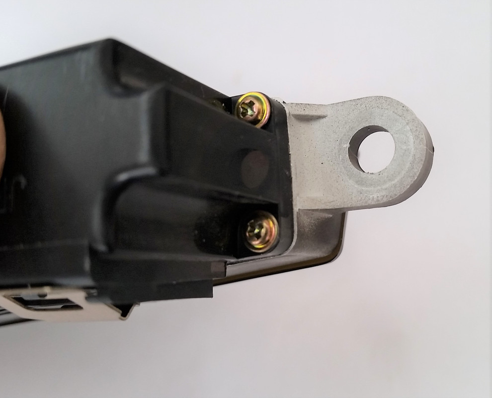
Reattach the assembly to the vent panel with the tabs and the 10mm head screw, reconnect the connectors, and snap the whole thing back in the dash.
Finished product:

A few tips for the first timers. I didn't take photos during disassembly, but the reassembly should hopefully identify all the important steps.
To pull the assembly out, simply pry at the whole HVAC vent assembly and pull. There are two connectors behind, disconnect them:
Then separate the clock assembly from the HVAC panel (one 10mm head screw, and some tabs).
Then separate the front and back housings from each other (tabs and three small Phillips screws).
Now you need to remove the "glass" (dark plastic really) by either dremeling or breaking off the six plastic posts. Also remove the circuit board from the housing by removing four small Phillips screws.
Now everything is apart. You need to solder the voltmeter leads to the three posts as shown by OP. My wire colors were different, but the functions the same. Black is ground, Red is constant 12V, White is 12V voltage triggered by the ignition key (you want to use this one, or else your voltmeter will always be on). Here are the posts to use:
Put the circuit board back in and reinstall the four screws:
Decide where you want to place the voltmeter and come up with a support system. I ended up gluing two pieces of plastic to act as supports, then glued the voltmeter tabs to these supports:
Now you need to cut an opening in the front of the clock housing for the voltmeter to show through. I made the opening as big as possible to maximize view angles:
Now you can snap the front housing back over the circuit board housing (the photo below is just a test fit, you can see that the buttons for the clock functions are not in place. They need to be reinstalled before reassembling the housings):
Now reattach the plastic face over the housings. I first used compressed air to blow out all the dremel shavings, I didn't want that white dust working its way in front of the clock or the voltmeter later on. Since the six mounting posts were broken off during disassembly, I used hot glue to reattach them together:
Reattach the assembly to the vent panel with the tabs and the 10mm head screw, reconnect the connectors, and snap the whole thing back in the dash.
Finished product:
Last edited by lyonkster; Apr 15, 2018 at 04:04 PM.
Advanced
Joined: Dec 2005
Posts: 550
Likes: 25
From: ca
https://smile.amazon.com/gp/product/...?ie=UTF8&psc=1
Lead Lap
Joined: May 2015
Posts: 449
Likes: 49
From: Illinois
Got the green 12v volt meter mod done and it turned out great. Make sure you make the opening as large as you can so you can view the volt meter at different angles. Also I painted everything black and even around the volt meter it's-self because you will see white when the sun hits it if its is not black.
Attachment 490051
Attachment 490052

Attachment 490051
Attachment 490052

Intermediate


Joined: Apr 2018
Posts: 481
Likes: 118
From: WA
It was the right idea to paint everything (including the sides of the LED display and the PCB) in black.
That makes all these components completely invisible through the dark lens.
Great job shwalker07!
That makes all these components completely invisible through the dark lens.
Great job shwalker07!

Lead Lap
Joined: May 2015
Posts: 449
Likes: 49
From: Illinois
Yes, very accurate. I get 13.5v at idle with normal electrical loads on, 14.1v to 14.0v with a light electrical load and it drops to about 12.9V with a heavy electrical load such as the high beams on, rear defrost, fan on full and radio turned up. Keep in mind a normal functioning charging system will read 13.5v to 14.5v.
I also compared volt readings with my multi-meter at the cigarette lighter and with my radar detector plugged in with a built in volt meter and all 3 are within .1v difference.
There is also a small adjustment **** on the back of the voltmeter if you needed to adjust the volt reading but I did not need to on mine.