

120V 30 Amp Circuit | EV Charging


Thread Starter
8th Gear
Joined: Nov 2024
Posts: 8
Likes: 4
From: SF BAY AREA, CA
Hello Everyone,
I am looking to utilize an existing circuit in my garage.
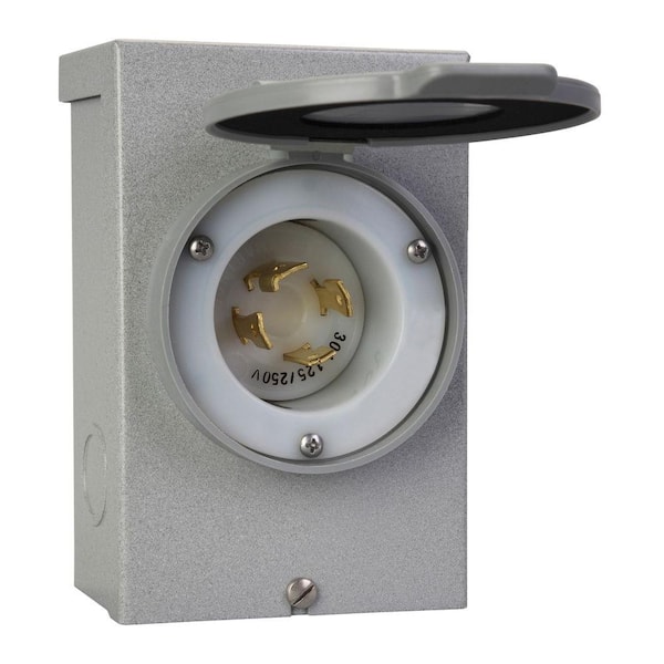
It is a 120V, 30A L5-30 Outlet.
I was wondering if anyone has any UL certified pigtail recommendations to convert the L5-30 to a NEMA Standard and then a potential EV charging solution you use?
Thanks!
I am looking to utilize an existing circuit in my garage.
It is a 120V, 30A L5-30 Outlet.
I was wondering if anyone has any UL certified pigtail recommendations to convert the L5-30 to a NEMA Standard and then a potential EV charging solution you use?
Thanks!
CL Community Team


Joined: Feb 2007
Posts: 9,312
Likes: 584
From: IL
Is this circuit used for anything else? By far the best option would be to convert it to a 240V circuit and install a hardwired charger that can be configured for a 30A circuit (which will cap charging speed at 240V/24A). This would involve having an electrician replace the single-pole breaker with a double-pole, and then landing the wire that currently serves as neutral on the second pole of the new breaker. Most EVSEs only require three wires: 2 hots (L1 and L2) and a ground. So the existing wiring should be fine.
If you don't want to do that (ie you need that outlet for something else in the garage, switching back and forth with the EVSE), any adapter that goes from L5-30 to 5-20R will allow you to use whatever 120V charger you like. But you'll be capped at 16A, or about one-third the output of the above solution. I don't know of any chargers that will do 20A or more on 120V, because it's just not a common configuration.
If you don't want to do that (ie you need that outlet for something else in the garage, switching back and forth with the EVSE), any adapter that goes from L5-30 to 5-20R will allow you to use whatever 120V charger you like. But you'll be capped at 16A, or about one-third the output of the above solution. I don't know of any chargers that will do 20A or more on 120V, because it's just not a common configuration.
Last edited by geko29; Nov 5, 2024 at 06:44 AM.
CL Community Team
Joined: Feb 2007
Posts: 9,312
Likes: 584
From: IL
 But hopefully not.
Thread Starter
8th Gear
Joined: Nov 2024
Posts: 8
Likes: 4
From: SF BAY AREA, CA
Is this circuit used for anything else? By far the best option would be to convert it to a 240V circuit and install a hardwired charger that can be configured for a 30A circuit (which will cap charging speed at 240V/24A). This would involve having an electrician replace the single-pole breaker with a double-pole, and then landing the wire that currently serves as neutral on the second pole of the new breaker. Most EVSEs only require three wires: 2 hots (L1 and L2) and a ground. So the existing wiring should be fine.
If you don't want to do that (ie you need that outlet for something else in the garage, switching back and forth with the EVSE), any adapter that goes from L5-30 to 5-20R will allow you to use whatever 120V charger you like. But you'll be capped at 16A, or about one-third the output of the above solution. I don't know of any chargers that will do 20A or more on 120V, because it's just not a common configuration.
If you don't want to do that (ie you need that outlet for something else in the garage, switching back and forth with the EVSE), any adapter that goes from L5-30 to 5-20R will allow you to use whatever 120V charger you like. But you'll be capped at 16A, or about one-third the output of the above solution. I don't know of any chargers that will do 20A or more on 120V, because it's just not a common configuration.
10.06 hours to fully charge the 18.1 kWh battery using a 120V, 15A charger on a 20A fuse.
6.28 hours to fully charge the battery using a 120V, 24A charger on a 30A fuse.
6.5 hours is still plenty enough since I can get the car on a charger in that time frame prior to heading out.
From the wire's perspective, 30A is 30A. So if the current outlet is to code--meaning wire is at least 10AWG--then changing one wire from neutral on a 120V to hot on a 240V breaker will also be to code. Of course, they could get in there and find that it's actually 8AWG, in which case the circuit could be converted to 240V/40A. Or they could find that it's 12AWG, and some unscrupulous person just put a 30A receptacle on a 20A circuit at sometime in the past. But hopefully not.
But hopefully not.
CL Community Team
Joined: Feb 2007
Posts: 9,312
Likes: 584
From: IL
Circuit to my knowledge.... It was a circuit used to power the house via Generator once the main source was off. So if power went out, the previous tenant used a generator to plug into it and power the home. I have that generator still, and they have provided a tested SOP for it. I am very unfamiliar with electrical, but my concern before was, I always thought outlets provided power vs receiving power. I would like to maintain that capability, but honestly it won't be a big deal to keep it as 120v since I am able to charge before I head out to work.
I have a 240V/30A power inlet (not outlet) on the back of my house that I use for the same purpose. It looks like this:
There are other types, but they're all the same basic idea. You connect the generator by using an RV extension cord.
The bolded part of your post is a HUGE concern. It guarantees one very serious code violation and safety issue, and suggests another one is likely. The cable that is used to backfeed a generator by plugging it into an outlet is called a "suicide cord" for very good reason. There should NEVER EVER be a situation in which an exposed prong can possibly be carrying live current.
The only safe way to use a generator to backfeed your home is to use an inlet like the one pictured above, which is wired to a breaker that is equipped with a lockout. A lockout is a device that makes it physically impossible for your main breaker and the generator backfeed breaker to be on at the same time. Mine looks like this, though it would be different for each type of load center:

When that plate is in the down position, the generator breaker is physically prevented from being switched on. But to slide it up and free the generator breaker, you have to turn off the main breaker at the top. At which point the generator breaker being on physically blocks the main breaker. This is needed for two reasons: First, to ensure those exposed prongs in the inlet cannot carry live current when the grid is functioning. Second, to ensure that your generator cannot backfeed into the grid, where it can potentially kill a lineman who's trying to restore your service.
If you do not have some variant of both of the things pictured above, you definitely need to call an electrician and find out what the safest path forward is. If you do have both of them, this circuit cannot be used for an EV charger, because there is no way for it to be live while your power is on.
i'm no electrician, but...
W = V x A
W = 120 x 30 = 3600
W = 240 x 30 = 7200
so if amps is amps and voltage doesn't matter, how can the higher voltage deliver twice the power? (usually needs thicker wires!)
so your thread topic says EV but you're referring to a plugin-hybrid vehicle with a much smaller battery?
eek, i think i'd have an electrician check all that out.
W = V x A
W = 120 x 30 = 3600
W = 240 x 30 = 7200
so if amps is amps and voltage doesn't matter, how can the higher voltage deliver twice the power? (usually needs thicker wires!)
I would like to not change it if it messes up the ability to power the home from a generator that was left by prior owners? But I am really unsure of how it all works, which is why I seek help from the community
Trending Topics
CL Community Team
Joined: Feb 2007
Posts: 9,312
Likes: 584
From: IL
L1: +120V
L2: -120V
N: 0V
The + and - are the oversimplification. That's not quite how AC current works, but it's good enough conceptually. So on a 30A/120V circuit, you have two of these three wires: A neutral, and either L1 or L2. The voltage of the circuit as seen by the load is determined by the difference in potential between the two wires. Whether you've got the L1 or L2, the "distance" from that to 0 is 120V. 120V outlets are 3 prongs because you have these two conductors plus a ground. Some circuits have L1/N/G, some have L2/N/G.
Now, let's say you want a 30A/240V (only) circuit. For this you also need two of these three wires, but this time it's L1 and L2. The "distance" from +120V to -120V is 240V, so that's what the load sees. Now, most 240V outlets actually have 4 prongs, not 3, because the neutral is included in case something actually needs 120V off that outlet (common with things like dryers and ovens), and of course the ground is there for safety. But the Neutral isn't actually necessary if 240V is all you need.
Regardless of which style outlet you're using, the ampacity of the individual conductors remains the same--in this case, 30A.
Thread Starter
8th Gear
Joined: Nov 2024
Posts: 8
Likes: 4
From: SF BAY AREA, CA
@geko29 Thank you for taking the time to go in depth about this. Based off what you and others have stated, I will not use the outlet then, and call an electrician for the best and safest path forward. 
Lexus Champion


Joined: Nov 2013
Posts: 13,195
Likes: 1,844
From: WA
There are a lot of projects around the house that I am willing to take care of myself, but wiring really isn't one of them. I needed a 120V/30A plug installed and was all too happy to write my electrician a check... 
CL Community Team
Joined: Feb 2007
Posts: 9,312
Likes: 584
From: IL
Corrected your post. Voltage (potential) has absolutely nothing to do with the size of the conductor. It’s all about current (Amperage) carrying capability. Case in point: tasers deliver 10,000+ volts over teeny tiny wires that couldn’t charge your cell phone at 5V. Here’s a chart that identifies the correct sizes:
:max_bytes(150000):strip_icc()/electrical-wire-sizes-1152851-final-f9b6499b4a564c5e9f644b241a7e619f.png)
Additionally, in household wiring, the voltage on the conductors isn’t actually changing whether the circuit is 120V or 240V. It’s always 120V. But the wires bringing 200A service (at 120V per leg) are almost a half-inch thick, whereas those for a 10A circuit could be one-twentieth of an inch thick.
Additionally, in household wiring, the voltage on the conductors isn’t actually changing whether the circuit is 120V or 240V. It’s always 120V. But the wires bringing 200A service (at 120V per leg) are almost a half-inch thick, whereas those for a 10A circuit could be one-twentieth of an inch thick.
Last edited by geko29; Nov 5, 2024 at 04:10 PM.
Lexus Fanatic
Joined: Sep 2010
Posts: 25,917
Likes: 4,274
From: Alberta
CL Community Team
Joined: Feb 2007
Posts: 9,312
Likes: 584
From: IL
Because the power (Watts) required by the device on the other end didn’t change, or increased only slightly. Multiply the voltage by 4x and you only need 1/4 the current (Amps) to achieve the same power delivery. Because less current is required, the wiring can be smaller. But make no mistake, if you replaced something that took 20A at 12V with something that took 20A at 48V, the wire size would remain the same.
For 48V cars that utilize a SMG in place of the alternator, those specific cables are still quite large, because the current requirements for an SMG are similar to or even higher than the 12V alternator they replaced. High current, large cable. Voltage is immaterial, except to the degree it allows you to decrease current.
But for an EVSE, your main goal is to increase power. Which is why ideally you increase voltage (which increases power). AND current (which increases power). Go from 120V to 240V, you double power. Go from 30A/240V to 60A/240V and you double power again. The doubling of voltage does not require larger conductors. The doubling of current absolutely does.
Last edited by geko29; Nov 6, 2024 at 03:10 AM.
