When you click on links to various merchants on this site and make a purchase, this can result in this site earning a commission. Affiliate programs and affiliations include, but are not limited to, the eBay Partner Network.
OK CL, this off season I have quite a few things to do to the 1J SC4 and I decided to start a build thread..
1. Installing BC264 cams
2. While apart, stock cam gears will be getting powder coated
3. Installing 550cc injectors and resistor box
4. Custom radiator setup with inlet on passenger side and water neck modified to accommodate. This way, I can more easily show off my powder'd cam gears Water neck stock twins recirc barbs will be removed and NPT ports in their place for my temp sensors.
5. Auto trans pulled and sent out for Stage 3 upgrade to ATF, and torque converter sent out for rebuild/upgrade
Here is a reference pic of how the bay currently looks:
This radiator is for a 79-93 mustang and has inlet on passenger side and outlet on driver side so that I can come out of the head straight in rather than cutting across the front of the motor and blocking view of my cam gears. The core is a few inches narrower than the SC radiator, but it has 2 rows with 1" tubes, which theoretically has about 60% more cooling capacity than a similar 3 rowradiator which typically have .63" tubes. And even more than those that have only .5" tubes.
It is an American Eagle brand, model #AE138. I will also be putting a shroud on this one, which I did not have on the other one. I would sometimes idle at redlights on hot days at 200-201 degrees. So, we will see how this works out
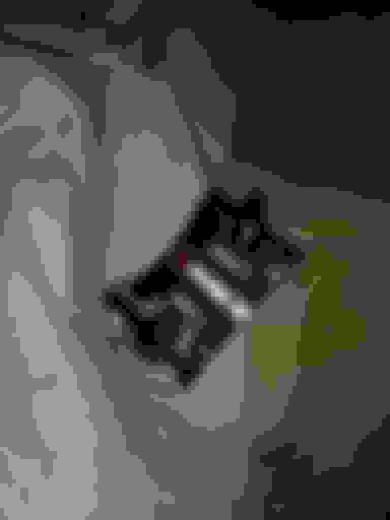
This is my spare water neck that I purchased from forum member PoGikoSc4 (thanks Rey!) It will get chopped and welded for a straight exit, rather than elbowing in front of motor. Also in the box is a new water neck gasket, a couple water neck to water pump tube gaskets, and new cam seals, all from driftmotion. The sucker was also from driftmotion, and I lmao when I opened the box.
USDM MKIV 550cc injectors and resistor that I bought off Gerrb (thanks Gerry!)
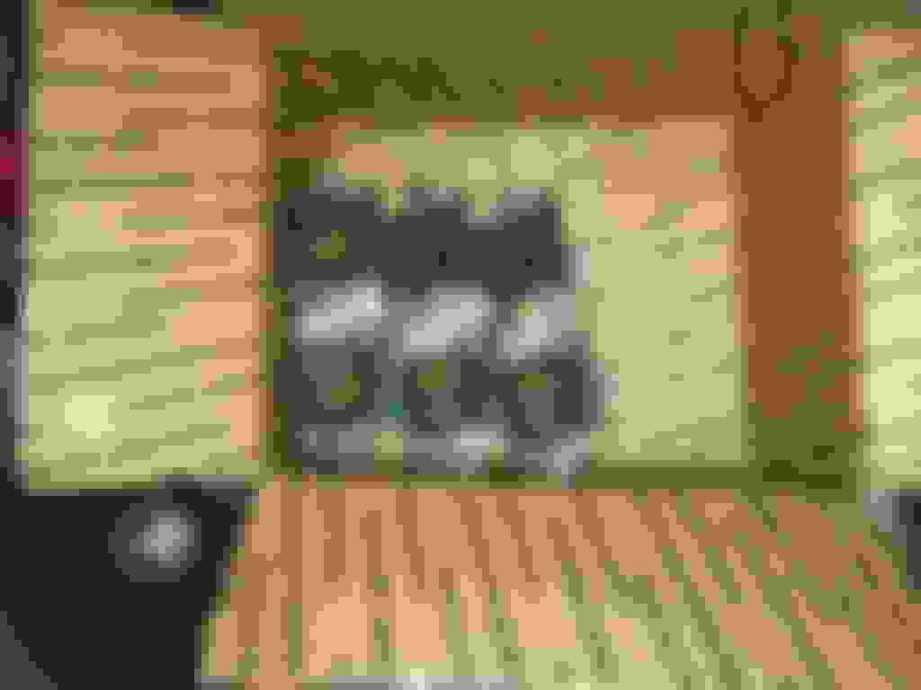
BC264 cams and offset feeler gauges for checking valve clearances before and after install.
Radiator removed. Lots of room in there. I also do not have the AC condenser which I took out a while ago.
Looks good so far man. Are you going to make your own shroud or cut an OEM one to fit? Did the radiator have a trans cooler built in or are you going with a separate cooler?
Looks good so far man. Are you going to make your own shroud or cut an OEM one to fit? Did the radiator have a trans cooler built in or are you going with a separate cooler?
Thank you I will be buying a shroud off ebay for the 79-93 mustang and just replace the crap electric fans that come with it with the two good fans that I have. I never had a shroud on the old radiator setup because it wouldn't fit with my intercooler piping right there. With this radiator, I can set it back more towards the front of the car like where the ac condenser used to be, and that will give me the extra room that I need. The radiator does have ports for trans cooler, but I will not be using them. I am running 1 of the biggest coolers that I could find (which you can actually see in one of the pics above), along with a standard size cooler. It actually is kind of hard to get the trans temp up to 160, so I know I have sufficient cooling. But then again, I can't do many pulls because it starts slipping around 140.
Originally Posted by 94_soarer
Looking forward to the outcome bro
Thanks man. If it comes out how I am picturing it, the bay should really look nice
starting in on it... I'm going to try to take as many pics as possible throughout the process, sort of like a DIY
Removing the serpentine belt, water pump pulley, crank pulley.
First thing that I did was break loose the crank pulley bolt. Put a breaker bar with 22mm socket on the crank pulley bolt and rotate CLOCKWISE until you can position the breaker bar underneath and as close as possible to the underbody as shown below.
Then remove the 30A EFI fuse from the underhood fuse box. Give a very brief attempt to start the car, and the breaker bar will break the bolt loose. I did it this way because I did not have the SST tool for keeping the pulley still while wrenching on the bolt to break it loose. This worked fine for me.
Removing serpentine belt with 14mm socket and breaker bar on belt tensioner (rotate breaker bar clockwise):
Remove belt
Then, line up your timing marks. Line up the notch on the crank pulley with the 0 mark on the timing cover turning the pulley CLOCKWISE with ratchet and 22mm socket on bolt. Make sure that the cam gears timing marks are in line with the notches on the upper timing cover. If they are not, then rotate crank another 360 degrees and then they should be. Make marks on the timing belt right at the notches. This will help later when putting the belt back on.
Once lined up, take impact gun and remove the crank pulley bolt. Since it was already broken loose before, it should not try to move the pulley while getting it off. This is why I wanted to break the bolt loose earlier, so that your not moving the timing while getting the bolt off.
Then, you can remove the crank pulley:
They say to install the bolt a few threads in to give the pulley puller something to press against. I did that and when the going got tough, as I was threading in the puller bolt, it started to thread in the crank pulley bolt. So, I luckily had some fender washers laying around that fit perfectly inside the chamber of the pulley:
It is already off of the car in the pic, but you get the picture. I was then able to press up against the washers and was eventually able to get it off with air impact gun. Thing was stubborn
So this is where its getting left off for today:
Tomorrow, I am going to remove the serpentine belt tensioner, lower timing cover, and loosen up timing belt tensioner to remove the timing belt. Also going to remove spark plug cover, coils, and cam covers
Loosen 3 bolts and remove serpentine belt tensioner
Remove alternator for easier access to the timing belt tensioner which is on the bottom right of it
Remove 5 bolts from lower timing cover and take off
Remove timing belt retainer ring thingamajig
Remove timing belt tensioner. Note: you might be able to get away with not completely removing it and just loosening the 2 bolts up to the last thread or two to gain enough slack on the belt to pull off, and put back on. I had to remove it though. Its easier to not remove it because then you have to reset and re-compress the tensioner
Remove timing belt
Time to check valve clearances. Using ratchet and socket, turn cam clockwise until the lobe faces upward for the valves that you want to measure
With feeler gauge, measure the clearances. Use TSRM. There are plenty of places on the net to find one, I used this one (http://www.97supraturbo.com/Tech.html) (Engine Repair section) which is for 2JZ GTE. Intake clearances should be .06-.010”. Exhaust clearances should be .010-.014”. Done on cold engine.. Record values
Remove cam gears using crescent wrench on hex portion of cam shaft to hold still while spinning the bolt off
Remove 4 bolts and remove cover
Remove the 4 bolts on the first bearing caps. Tape up the end of a screwdriver and pry them up under the little tab
Make a cardboard holder for bearing caps and label them so that they can be put back on in the same spots. Each cap is also labeled with position and arrow for proper orientation
Remove all bearing caps on intake side in sequence as described in TSRM and place them on cardboard and remove camshaft
Remove all bearing caps on exhaust side in sequence as described in TSRM and place them on cardboard and remove camshaft
Grab new camshafts and lube them with fresh oil. I put a pair of gloves on and just rubbed oil all over them. Place them in position. Follow TSRM to install. It says to first install caps 3 & 7 and alternately tighten them until camshafts are flush to head. Be sure to apply oil to the bolts and under the head of the bolt, and on the cap where it meets with the cam. Then install new camshaft oil seal (brown seal on front of camshafts).
Follow sequence as described in TSRM for fastening the other caps. On both first caps, you will need to apply FIPG as shown. Be sure to follow TSRM as it is important to tighten the caps down in order as described to prevent camshaft/head warping. Also, TSRM will tell you to rotate the camshafts 120 degrees and then loosen and retorque some caps, then another 120 degrees and loosen and retorque some more caps, and then yet another 120 for the final caps. Torque rating of the bolts is 14 ft-lb
BC264 cams installed! Now check valve clearances again. Most of mine were the same as with stock cams, while some here and there were different by .001”. But they are all still in spec. And plus, it’s feeler gauges, so not the most accurate measurements… I recorded my measurements on the cardboard. Blue ink is with BC cams, and black ink was OEM cams


 Water neck stock twins recirc barbs will be removed and NPT ports in their place for my temp sensors.
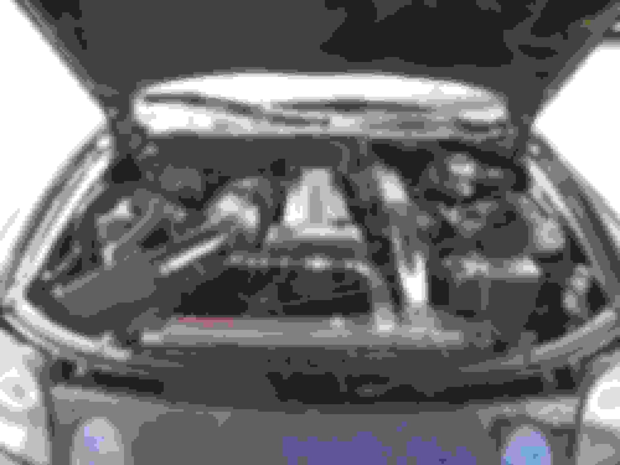


 I will be buying a shroud off ebay for the 79-93 mustang and just replace the crap electric fans that come with it with the two good fans that I have. I never had a shroud on the old radiator setup because it wouldn't fit with my intercooler piping right there. With this radiator, I can set it back more towards the front of the car like where the ac condenser used to be, and that will give me the extra room that I need. The radiator does have ports for trans cooler, but I will not be using them. I am running 1 of the biggest coolers that I could find (which you can actually see in one of the pics above), along with a standard size cooler. It actually is kind of hard to get the trans temp up to 160, so I know I have sufficient cooling. But then again, I can't do many pulls because it starts slipping around 140.