When you click on links to various merchants on this site and make a purchase, this can result in this site earning a commission. Affiliate programs and affiliations include, but are not limited to, the eBay Partner Network.
So, I bought the techstream cable to do some of the customizations and like it does for just about everyone else with the pre-2006 models, it turns on the the VSC and VSC OFF lights which then require a reset of the OBD by jumpering pins 4 & 14 of the OBD connector.
Part of my plans for the car computer involve having a bluetooth OBD reader plugged in just about all of the time. Reading around, these lights coming on seem to be common with just about any OBD reader.
I've read that the reason that this happens is because the OBD tries to connect first with the CAN bus. So, my first thought was, "well why not just prevent it from doing that?"
So, I opened my Techstream up and cut the trace going to pin 14 (CAN -) and no more VSC lights so far. I have not yet tested every feature, but so far everything in the techstream software appears to work.
A switch can be installed to reconnect the CAN line if you decide you need that for some reason.
To cut a trace with the least amount of damage, I use a dremel tool with the finest engraving bit. You just nick out a tiny chunk of the trace. If needed to be reversed, the cut is small enough to just drop a bit of solder there and reconnect it.
That is great info I plan to do the same on the PCB in the OBDII connector.
A big tks Retro! ;-)
There is a possibility that you lose some functionality that I am not aware of. I did this as a test, and plan to put a switch in there to reconnect it whenever I might need it. It's possible it uses the CAN bus for the TPM. Possibly. The mod is easily reversed, though.
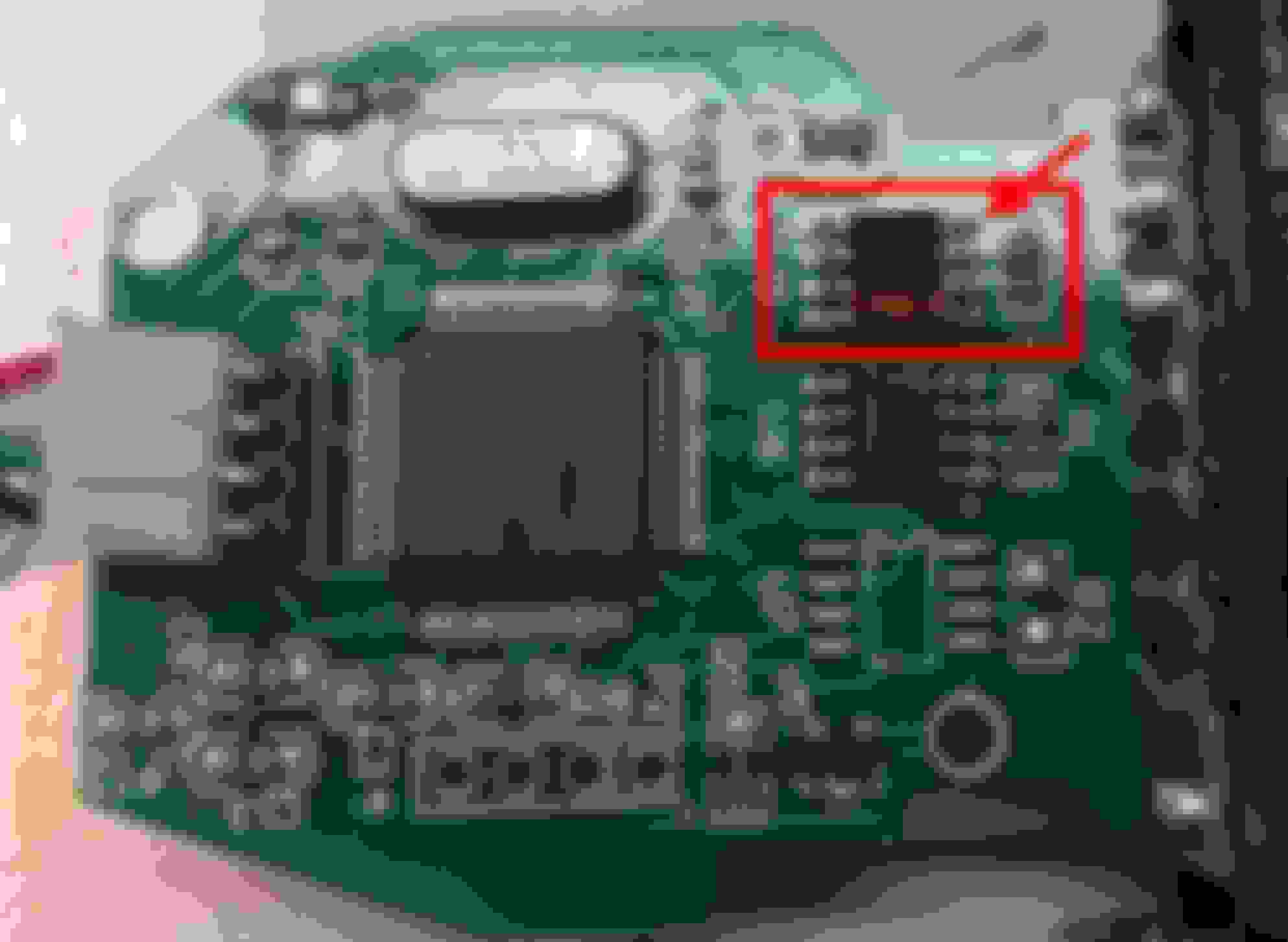
Another method would be to connect pin 8 of the IC marked TJA1050 to VCC with a switch. This would disable the CAN transmitter and disconnect it from the bus while still allowing reads. I have not tested this method yet, but I assume it would work and would keep the most functionality. It should already be connected to ground, so you don't want to just connect it directly to VCC or you will short out VCC and ground. It would require cutting the trace to ground and putting a switch in there to switch pin 8 between VCC (pin 3) and ground (pin 2.) Maybe I'll do that mod and show pictures.
I'm sure that not all OBD readers have a full-blown CAN transceiver in them, though.
Another idea might be to just wire in a switch connected to pins 4&14.
Flip the switch before you disconnect, no lights but you still have full functionality while using TechStream.
I had a chance to install a switch, but haven't had a chance to test it out yet. This switch would disable the CAN transmitter (putting it in silent mode) In silent mode, it can still read the CAN bus but cannot write to it. A flip of the switch puts it back to the way it came.
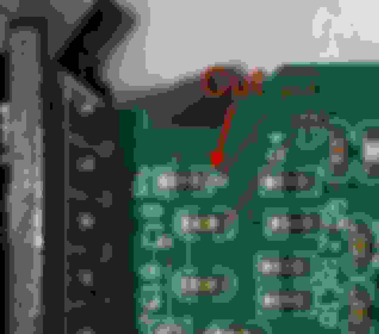
The secret is to take pin 8 on the CAN transceiver IC, cut the trace going to the pull-down resistor and install a spdt switch. The center goes to pin 8, and the extremes go back to the pulldown resistor(on) or to VCC (off).
CAN transceiver IC
Cut the trace here
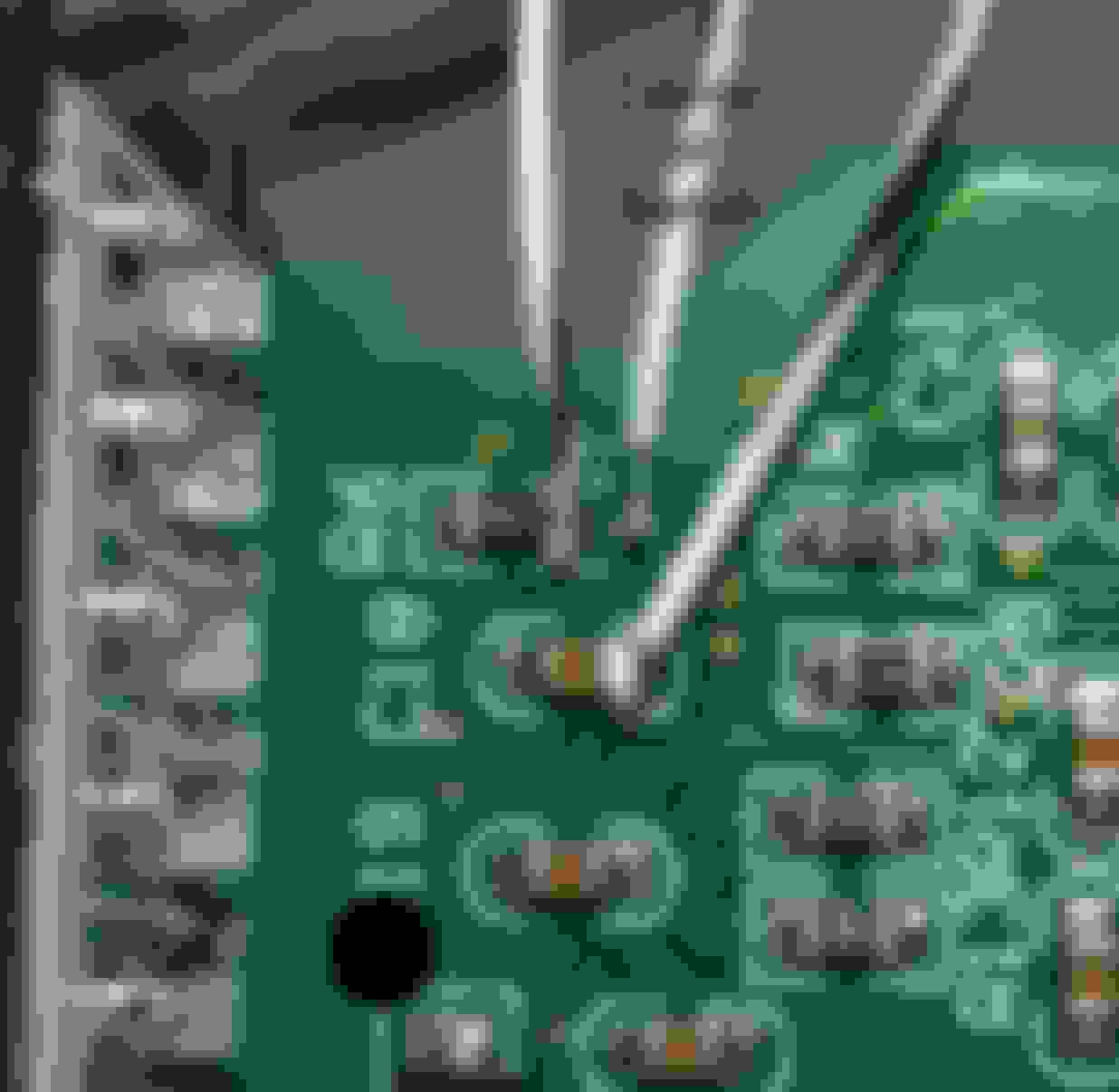
Wire up switch. Instead of soldering to the tiny pad in the center, you could solder to pin 8 of the IC on the other side.
Again, I have not tried it yet to make sure this doesn't still trip the VSC lights. I can't imagine that it would, but you might want to wait for me to try it out before attempting it.
I have confirmed that just cutting the trace to pin 14 works. I have not tested every feature of the Techstream cable, but so far what I have tested (read DTC codes, monitored, and ran some of the customizations) worked without issues. If anyone has any suggestions to try out, let me know. There are some functions that I am not sure what they do and have not wanted to mess around with until I do.
If the CAN bus is not needed in the cable on the SC430, then cutting the trace to pin 14 is the simplest option. Unless you wanted to use it as a generic OBD reader for another car that requires the CAN bus, you probably would never know the difference and never need a switch.
I will be doing this also to a bluetooth reader that I plan to leave plugged in.
Side note: There is an unpopulated header that appears to be the serial port. It may be possible to install a bluetooth module in the cable for wireless operation. Techstream should work with that since the USB is just connected to an USB to serial IC. I have one of these modules laying around and might give it a try.
Hope this helps in some way...I found it on a different Toyota forum
I found a long but good explanation of why the VSC lights come on...
If you suddenly have the "VSC TRAC" and "VSC OFF" lights in your dash, this post may help you fix the problem yourself. The information here applies to 4th gen 4Runners that use the ISO protocol rather than the newer CAN protocol for their OBDII interfaces to code readers, ECU programmers, hand-held testers, etc. The OBDII interface includes several different protocols (methods of digital communication) and they all use the same physical connector, though with some different pins. The connector is located at the bottom of the dash on the driver's side and in the 4Runner it's covered by a small black cap.
4Runners switched from ISO to CAN around 2005 though this information may also apply to newer 4Runners with some modification. That is, newer 4Runners may display trouble codes and reset sensor calibration values in response to the connection of different (than earlier 4Runners) pins together than the ones described below.
Several posters have discussed similar problems, described in several different threads. I'm reluctantly starting a new one, with a more specific title (including the exact name of the two trouble indicator lights), in the hope that searchers will more easily find a solution.
The specific behavior: On startup, the "VSC TRAC" and "VSC OFF" lights come on and stay on. The ABS light may or may not come on. On subsequent starts the lights will come on temporarily as usual (as a bulb check) and then go off. They come on again and stay on as soon as the 4Runner is moved. The "check engine" light does not come on. This behavior begins after the vehicle has been hooked to some sort of OBDII code reader or engine tester or data logger, etc. Though the lights are on, no standard OBDII problem codes are detected by a regular code reader.
Cause: The code reader or other OBDII device has attempted to communicate with the 4Runner using the CAN protocol (involving pin #14) and this has caused the 4Runner to erase the "zero point calibration" numbers in its memory. Without these numbers it can't get accurate information from the yaw rate and deceleration sensors (in the center console near the gearshift) and so it disables traction and stability control functions.
The fix: Perform the "zero point calibration" procedure as described in TSB BR001-04. This procedure can be performed without special equipment such as a hand-held tester or OBDII reader. You only need the equivalent of a jumper wire to short together two pins of the OBDII connector at the right time and the right number of times between switching the 4Runner on and off. More detail is included below, leveraged from my other posts.
Why this doesn't happen every time a code reader is used: The code readers usually use the pins and protocol of the OBDII connector in a specific sequence, trying first to establish communication with the vehicle using the oldest protocol. They then try the pins and protocol of newer protocol standards. Usually the code reader would be successful in its first try at establishing contact with the 4Runner using the ISO 9141-2 protocol, and there would be no problem. However these communications schemes are not foolproof and occasionally the ISO protocol attempt fails. Then the code reader tries newer protocols including CAN (controller area network). It's this CAN attempt, which toggles pin #14 (the CAN data pin) that accidentally tells the 4Runner to erase the existing zero point calibration data. Since the 4Runner (this vintage anyway) can't communicate by CAN protocol the tester re-tries the older protocols again and eventually succeeds in setting up communication by the right ISO protocol. But by then the calibration data has been erased.
The calibration, by the way, is simply a matter of telling the 4Runner VSC/TRAC computer "your yaw rate and deceleration rate are currently zero" and to save the associated values. Then the output from the sensors can be interpreted correctly.
Detail (may be helpful if you're going to do the calibration procedure yourself): The SST (special service tool #09843-18040) specified in the service manual appears to be essentially a Y-shaped test lead and is variously called a "jumper wire" or "diagnostic check wire." It's used in this case to repeatedly connect and disconnect the chassis ground (CG, pin #4) and Ts (pin #14) terminals of the OBDII connector (referred to as DLC3 in Toyota-speak). The connection/disconnection sequence and timing are described in the service manual and in several TSBs. OBDII connector diagram and pin descriptions are in TSB BR005-03.
Since the OBDII connector is at the lower edge of the dash and pointing down (right above your left foot when you're sitting in the driver's seat) it's rather tough to reach in and do the shorting to the appropriate terminals of the OBDII connector with a test lead. Especially since you're supposed to avoid moving or shaking the vehicle when you're doing this. BTW, the OBDII connector usually has a black snap-on cover over it to keep out grit, etc.
Therefore I took a couple of pieces of insulated wire about 24" long each and taped them alongside each other, and stripped both ends. To make the wire fit securely in the (female) terminals of the OBDII connector I soldered a 3/8" length of metal (cut from a heavy paper clip) to one end of each of the wires. I chose a pin size so that would fit securely in the female terminals of the OBDII connector but wouldn't distort them. I used some heat shrink tubing around the solder joint to reduce any chance of accidental shorting.
After plugging the two pins into the OBDII connector (with the other ends held apart) I was able to hold the other ends of the two wires in my hands and touch them together at the appropriate times to connect the pins of the OBDII connector. I had a helper in the passenger seat to read the instructions from the TSB to me in sequence.
This is not very hard to do, and one need only be careful. It's easier to do with the Toyota OBDII tester, of course, and would only take 5 minutes. You might be able to get your dealer to do it gratis, but you might also be charged some minimum labor hour rate.
BTW #1: Doing the sulfur TSB or others that require the replacement or reprogramming of the engine computer or the VSC computer will also require this calibration.
BTW #2: I verified that when the lights are on the VSC and traction control are indeed inoperative. ABS is working, though.
BTW #3: Shorting other pins (such as #13 Tc) at the right time can cause the appropriate dash indicators to blink in sequence to reveal trouble codes other than the OBDII ones. A generic OBDII code reader won't give you this data, and you need the service manual (physical or online) to make sense of it. I believe there is a specific code to tell you that the zero point calibration data has been lost, but I didn't look for it.
BTW #4: In the 4Runner of this vintage the OBDII connector pins populated are 4, 5, 7, 9, 13, 14, 15, 16
[Sorry about the long post, but I wanted to include the kind of information I'd want if I encountered this problem and wanted to feel comfortable fixing it myself]
[Sorry about the long post, but I wanted to include the kind of information I'd want if I encountered this problem and wanted to feel comfortable fixing it myself]
It would seem from that info that the consequences are more than just an annoyance and possibly not fully reset with the simple shorting of pins trick. All the more reason to simply cut that line and be done with it. It sounds as if the CAN bus is not used at all in this car, and instead pin 14 is being used as a vendor specific pin, like 13 coming from the navi. The only reason then to install a switch is if you wanted to use the tool on other cars.
I recieved a Viecar 2.0 bluetooth OBD scanner the other day. I did the ultimate dumb thing and didn't test it out before disconnecting pin 14. It seems to be having trouble detecting the protocol of the car in any of the programs I have tried so far. It doesn't seem like this would be connected to the disconnection of pin 14 since our vehicle doesn't even use that pin for OBD comms. But just putting this experience out there in case others might try it. So far, Techstream has had no issues with doing this, so it is perhaps just a crappy OBD scanner.
 09-23-15, 12:35 AM