
Hyperblink fix for 92-94 SC w/ 97 Taillights
 12-23-07, 01:43 AM
#1
So I decided to pickup some 97 tails from Eggman because it came with a modified flasher unit that gets rid of the hyperblink.
Props goes out to him for making the minor drilling necessary to install the new tails onto my car and for swapping out the flasher units.
Anyways, I always thought that the taillight ecu was modified in order to stop the hyperblink, but Eggman informed me that it was actually the flasher unit. The unit is located on the driver's side kick panel where the fusebox is.
I would like to note that neither Eggman or I modified the flasher unit and that we take no responsibility for doing this mod. We simply opened up an oem and modded flasher unit and compared them with pics. Therefore, there is no step by step writeup for this.
As a result, the blinking seems a tad shorter/faster than oem, but still significantly better than hyperblink.
I'll try to get a video up soon, but here are the pics/vid...
Vid - Emergency blinkers are slower than stock with this flasher unit.
http://youtube.com/watch?v=CNDQYwMqhIc
Pics (Credit goes to Eggman) can speak for themselves:
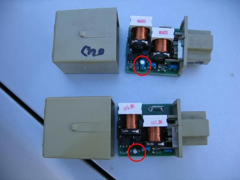
1. OEM on top MOD on bottom.
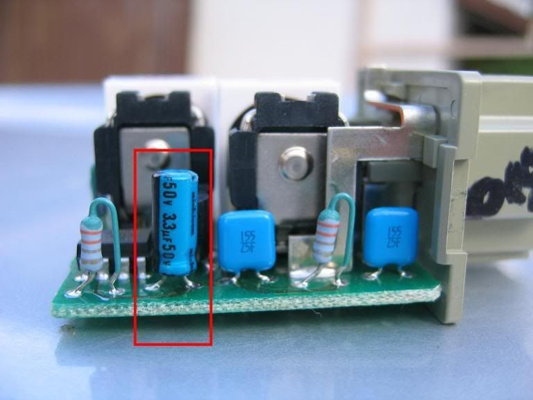
2. OEM closeup
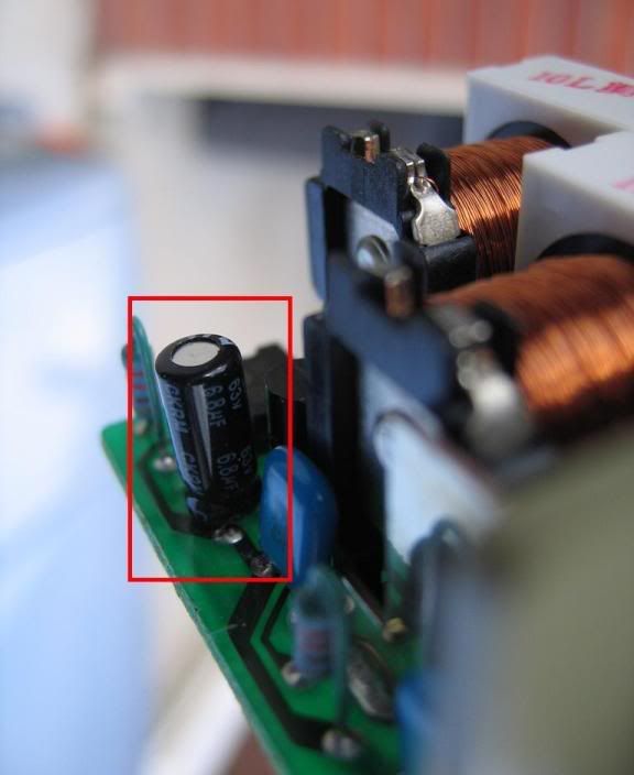
3. MOD closeup
Props goes out to him for making the minor drilling necessary to install the new tails onto my car and for swapping out the flasher units.
Anyways, I always thought that the taillight ecu was modified in order to stop the hyperblink, but Eggman informed me that it was actually the flasher unit. The unit is located on the driver's side kick panel where the fusebox is.
I would like to note that neither Eggman or I modified the flasher unit and that we take no responsibility for doing this mod. We simply opened up an oem and modded flasher unit and compared them with pics. Therefore, there is no step by step writeup for this.
As a result, the blinking seems a tad shorter/faster than oem, but still significantly better than hyperblink.
I'll try to get a video up soon, but here are the pics/vid...
Vid - Emergency blinkers are slower than stock with this flasher unit.
http://youtube.com/watch?v=CNDQYwMqhIc
Pics (Credit goes to Eggman) can speak for themselves:
1. OEM on top MOD on bottom.
2. OEM closeup
3. MOD closeup
Last edited by TheMole; 01-05-08 at 04:55 PM.
 12-23-07, 02:09 AM
#2
Keeper of the light
iTrader: (17)
Cool. I did a thread on here that showed you a modified flasher that was adjustable and you could make it blink at any rate.
That cap does not directly control the flash. The cap feeds the 555 style timer chip and it changes the input to the timer chip, which is what really controls the flashing relays. The cap changes works, but I don't like the way it was went about being done.
You can confuse the chip with too much variance in the capacitor. If you are ever in an accident or need your hazards (which we only need them at the worst times) the chip may become confused if the capacitor value is too far off for the 555 timer to get the proper signal it wants to see to perform the "clock" function it has to do. It can happen with the turn signals just as easily, but not as serious of a situation unless you live in the city. The chip is digital and needs a digital high of +5v and a digital low of 0v. When the capacitor is off too much it undercuts the input voltage and can wig the clock out in the timer chip.
Last edited by O. L. T.; 12-23-07 at 02:16 AM.
12-23-07, 02:18 AM
#3
Cool. I did a thread on here that showed you a modified flasher that was adjustable and you could make it blink at any rate.
That cap does not directly control the flash. The cap feeds the 555 style timer chip and it changes the input to the timer chip, which is what really controls the flashing relays. The cap changes works, but I don't like the way it was went about being done.
You can confuse the chip with too much variance in the capacitor. If you are ever in an accident or need your hazards (which we only need them at the worst times) the chip may become confused if the capacitor value is too far off for the 555 timer to get the proper signal it wants to see to perform the "clock" function it has to do. It can happen with the turn signals just as easily, but not as serious of a situation unless you live in the city. The chip is digital and needs a digital high of +5v and a digital low of 0v. When the capacitor is off too much it undercuts the input voltage and can wig the clock out in the timer chip.
That cap does not directly control the flash. The cap feeds the 555 style timer chip and it changes the input to the timer chip, which is what really controls the flashing relays. The cap changes works, but I don't like the way it was went about being done.
You can confuse the chip with too much variance in the capacitor. If you are ever in an accident or need your hazards (which we only need them at the worst times) the chip may become confused if the capacitor value is too far off for the 555 timer to get the proper signal it wants to see to perform the "clock" function it has to do. It can happen with the turn signals just as easily, but not as serious of a situation unless you live in the city. The chip is digital and needs a digital high of +5v and a digital low of 0v. When the capacitor is off too much it undercuts the input voltage and can wig the clock out in the timer chip.
Great info on how that piece works. Also, what is the title of the thread you made with the adjustable flasher unit?
 01-05-08, 04:02 PM
#7
I really want to see the video.
I found the this as well.
http://www.soarer.tv/EMV_Repair/Flashertut.jpg
I found the this as well.
http://www.soarer.tv/EMV_Repair/Flashertut.jpg


