Notices
SC430 - 2nd Gen (2001-2010)

Help with wiring under seats, please.

Thread Tools
 
Search this Thread
 
Old Jul 30, 2021 | 02:00 PM
  #46  
WtSpyder's Avatar
WtSpyder
Thread Starter
Pit Crew
 
Joined: Feb 2021
Posts: 162
Likes: 41
From: MS
Default

Got a new seat position ecu and swapped it out with the old one. New seat position switch. No movements from the 8 way control. All but the one circled on the black connector are showing 12.4 volts with a multi-meter. What next??
Reply
Old Aug 4, 2021 | 05:35 AM
  #47  
WtSpyder's Avatar
WtSpyder
Thread Starter
Pit Crew
 
Joined: Feb 2021
Posts: 162
Likes: 41
From: MS
Default

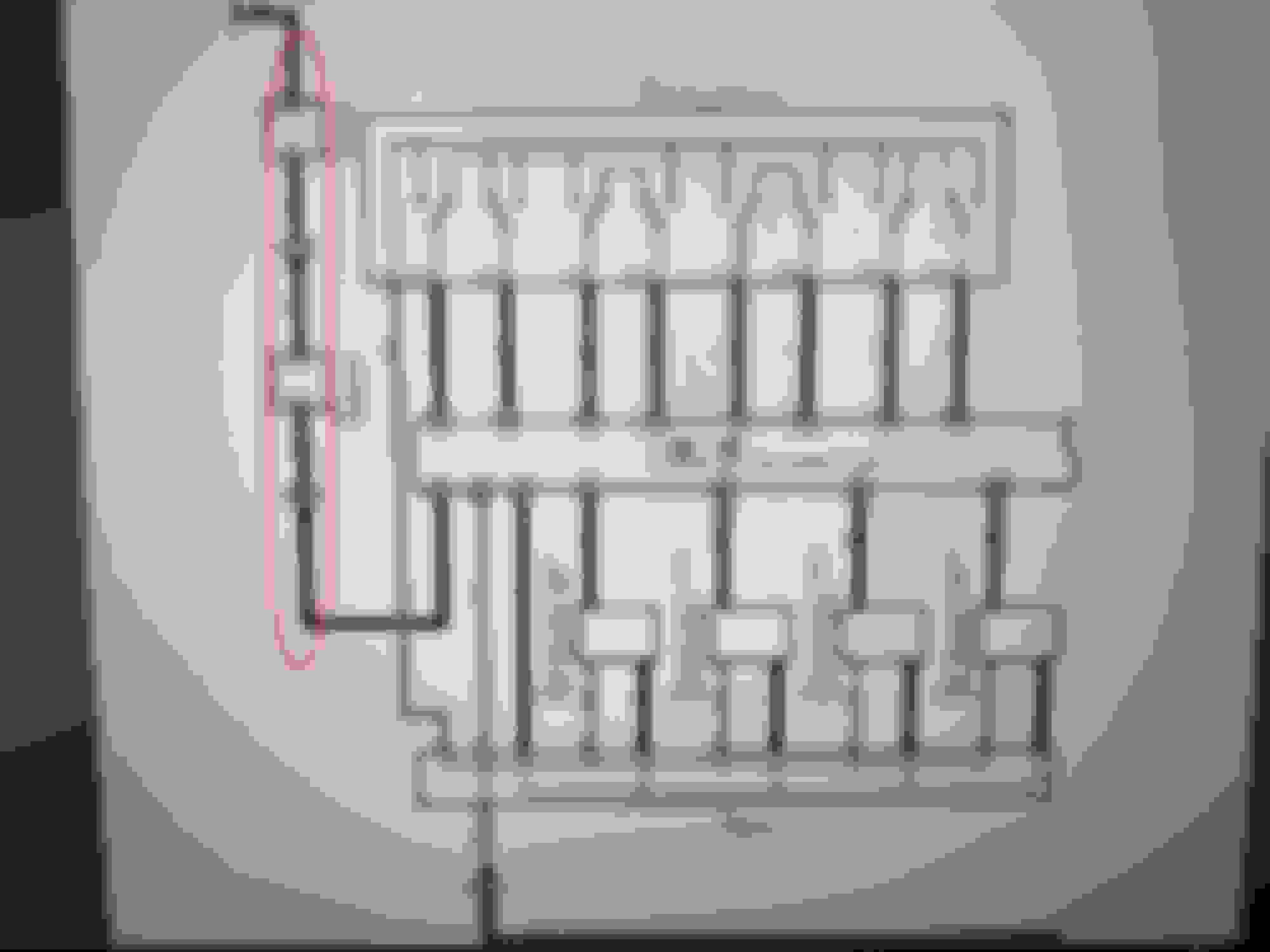
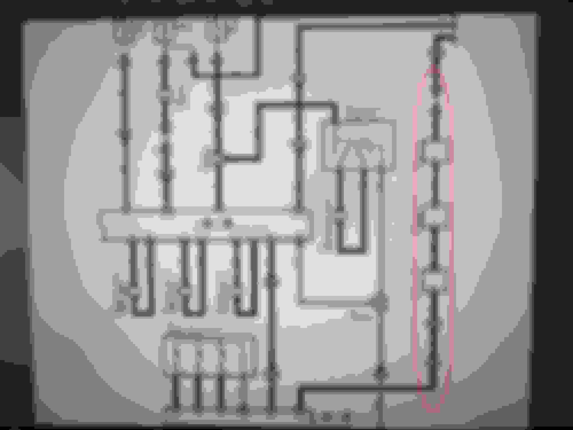
In studying the schematics, I have a question for those who understand them better than me. In the photo below, the item circled in red appears to get power from the second photo showing the driver side. My question is which pin on the cream connection block from the passenger floor is associated with the circuit in question?


Reply
Old Aug 4, 2021 | 10:12 AM
  #48  
Bgw70's Avatar
Bgw70
Lexus Test Driver
10 Year Member
Veteran: Air Force
Liked
Community Favorite
 
Joined: Dec 2014
Posts: 8,213
Likes: 952
From: Fl
Default

Do you know the color codes for the wires?

this might help if you don’t…

Reply
Old Aug 4, 2021 | 10:14 AM
  #49  
Bgw70's Avatar
Bgw70
Lexus Test Driver
10 Year Member
Veteran: Air Force
Liked
Community Favorite
 
Joined: Dec 2014
Posts: 8,213
Likes: 952
From: Fl
Default


Reply
Old Aug 4, 2021 | 06:09 PM
  #50  
digitatc's Avatar
digitatc
Instructor
5 Year Member
Liked
Loved
Community Favorite
 
Joined: Feb 2017
Posts: 765
Likes: 270
From: ca
Default

Here is the seat diagram so you can see which connector is which.

Attached Files
File Type: pdf
Seat diagram.pdf (1.62 MB, 98 views)
Reply
Old Aug 5, 2021 | 06:27 AM
  #51  
WtSpyder's Avatar
WtSpyder
Thread Starter
Pit Crew
 
Joined: Feb 2021
Posts: 162
Likes: 41
From: MS
Default

First, let me say thanks to all that have helped with diagrams and other information. This is what this group is all about.

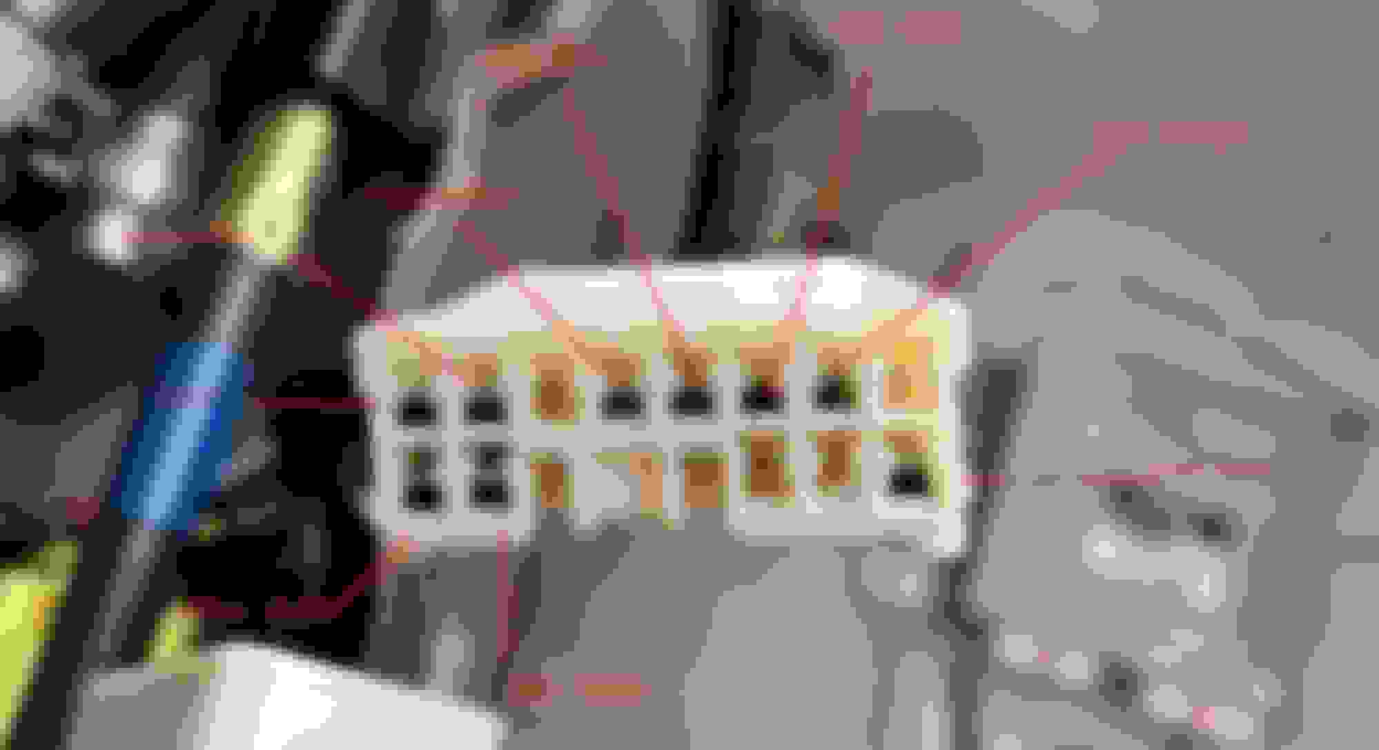
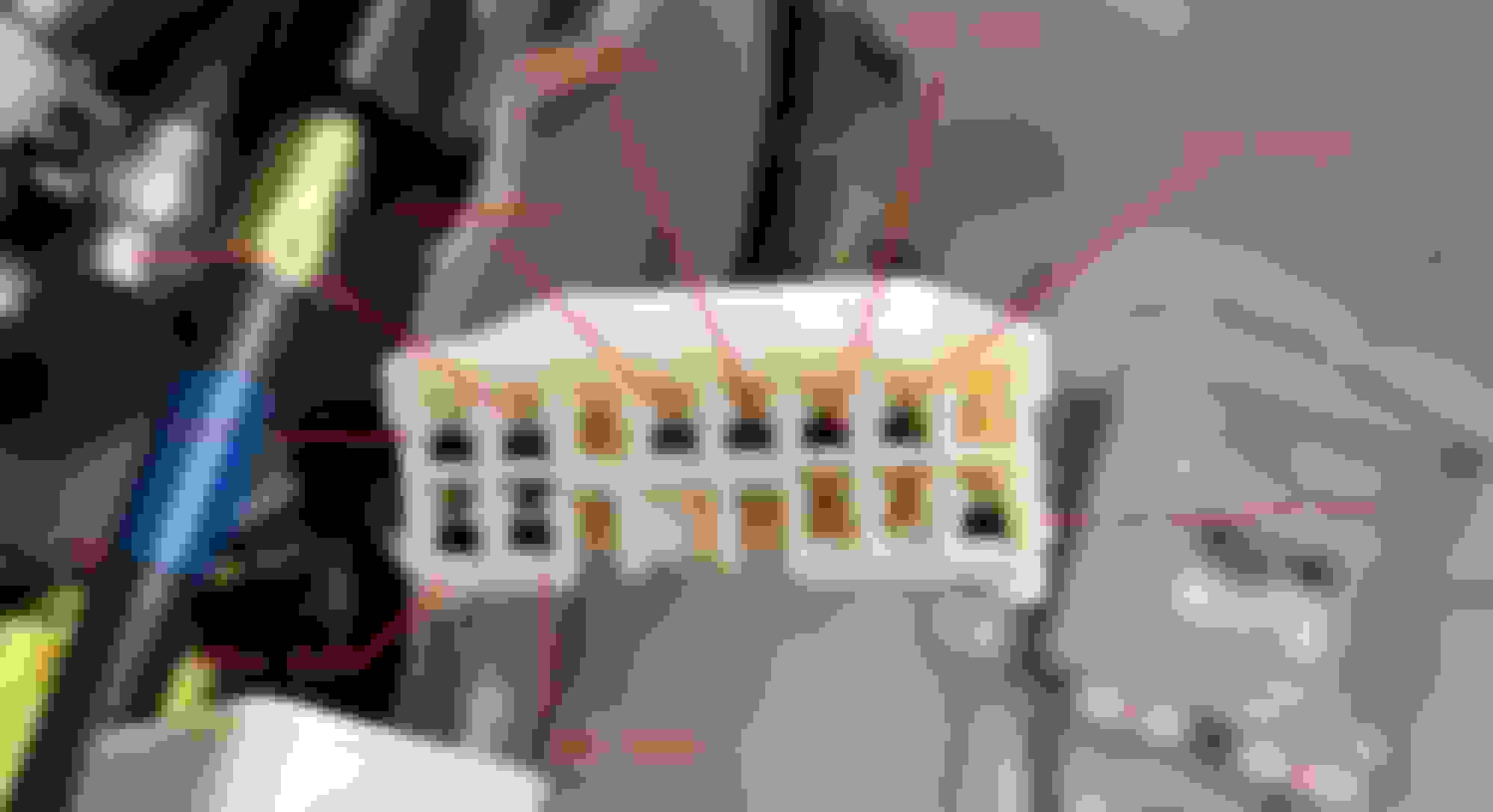
Below is another photo of the white connector coming from the floor on the passenger side. I have labeled each of the lines with the color wire associated with it. In the electrical schematics provided above, a R-L (Red -Blue) is shown to be coming from the driver side to the passenger seat ECU. I do not see this color line in the white connector. This R-L line shows going to the passenger door ECU first. then becomes a B-Y (black - yellow) going into the sliding roof control ECU. It leaves there as a G (green) going into the passenger seat ECU. Is this the larger gauge LG (light green ) linge in the white connector coming from the floor?


Reply
Old Aug 5, 2021 | 07:35 AM
  #52  
WtSpyder's Avatar
WtSpyder
Thread Starter
Pit Crew
 
Joined: Feb 2021
Posts: 162
Likes: 41
From: MS
Default

Additional information for diagnosis

The voltage at each line of the white connector

With the key off

Blue - Orange 12.54v
Blue - White 12.54v
Pink - Blue 1.00v
Green w/silver 1.00v
Blue w/silver 0.00v
Brown 0.00v
White - Black 0.00v
Blue - Yellow 0.00v
Light Green 0.00v

With engine running:

Blue - Orange 12.54v
Blue - White 12.54v
Pink - Blue 1.00v
Green w/silver 1.00v
Blue w/silver 0.00v
Brown 0.00v
White - Black 0.00v
Blue - Yellow 0.00v
Light Green 12.54v

Does anyone know what each of the lines from this connector do? Is this the correct state for not running and running?

Thanks in advance.


Reply
Old Aug 5, 2021 | 07:36 AM
  #53  
Bgw70's Avatar
Bgw70
Lexus Test Driver
10 Year Member
Veteran: Air Force
Liked
Community Favorite
 
Joined: Dec 2014
Posts: 8,213
Likes: 952
From: Fl
Default

The connector you are showing on the passenger side is BE1…Drivers side is BD1
most of the wires you labeled match my diagram.


Reply
Old Aug 5, 2021 | 07:40 AM
  #54  
Bgw70's Avatar
Bgw70
Lexus Test Driver
10 Year Member
Veteran: Air Force
Liked
Community Favorite
 
Joined: Dec 2014
Posts: 8,213
Likes: 952
From: Fl
Default

The Brown and White/Black on the left side of the connector BE1 are grounds. Make sure they are good.


Reply
Old Aug 5, 2021 | 08:39 AM
  #55  
WtSpyder's Avatar
WtSpyder
Thread Starter
Pit Crew
 
Joined: Feb 2021
Posts: 162
Likes: 41
From: MS
Default

Originally Posted by Bgw70
The connector you are showing on the passenger side is BE1…Drivers side is BD1
most of the wires you labeled match my diagram.

This is great information! Is there a table that identifies each of the numbered ports? I see in your following post that the line coming from the roof ECU goes through connector BE1 as a green wire, in and out, which number is it on the connector?

thanks again, just not familiar with reading these things.

Reply
Old Aug 5, 2021 | 09:13 AM
  #56  
Bgw70's Avatar
Bgw70
Lexus Test Driver
10 Year Member
Veteran: Air Force
Liked
Community Favorite
 
Joined: Dec 2014
Posts: 8,213
Likes: 952
From: Fl
Default

I will help you understand how to read them…BTW, I may make errors.
go to post 54, look at the green wire at BE1,
next to BE1 is the number 10.
Now go to the connectors pic for BE1…
now go to your connector pic,
turn your pic over to match my connector pic.
What color is that wire?
Reply
Old Aug 5, 2021 | 09:35 AM
  #57  
WtSpyder's Avatar
WtSpyder
Thread Starter
Pit Crew
 
Joined: Feb 2021
Posts: 162
Likes: 41
From: MS
Default

Originally Posted by Bgw70
I will help you understand how to read them…BTW, I may make errors.
go to post 54, look at the green wire at BE1,
next to BE1 is the number 10.
Now go to the connectors pic for BE1…
now go to your connector pic,
turn your pic over to match my connector pic.
What color is that wire?
Appears to be a green wire with silver tick marks on it. If that is the feed, is the constant 1.00v correct?

Reply
Old Aug 5, 2021 | 09:45 AM
  #58  
Bgw70's Avatar
Bgw70
Lexus Test Driver
10 Year Member
Veteran: Air Force
Liked
Community Favorite
 
Joined: Dec 2014
Posts: 8,213
Likes: 952
From: Fl
Default

Originally Posted by WtSpyder
Appears to be a green wire with silver tick marks on it. If that is the feed, is the constant 1.00v correct?
the green wire pin 10 is a multiplex line which should be digital logic…10101010101010 and just me guessing, I would say yes 1vdc may be correct.

focus on the two ground points on the connector pins, are they good?
what about the 12vdc power connector pins?
Reply
Old Aug 5, 2021 | 09:50 AM
  #59  
Bgw70's Avatar
Bgw70
Lexus Test Driver
10 Year Member
Veteran: Air Force
Liked
Community Favorite
 
Joined: Dec 2014
Posts: 8,213
Likes: 952
From: Fl
Default

Oops, I see you posted the two power connections as good.
BE1 pins 7&8 both have 12vdc.

let me look at the grounds now.
Reply
Old Aug 5, 2021 | 09:57 AM
  #60  
Bgw70's Avatar
Bgw70
Lexus Test Driver
10 Year Member
Veteran: Air Force
Liked
Community Favorite
 
Joined: Dec 2014
Posts: 8,213
Likes: 952
From: Fl
Default

BE1 pins 5&13 are ground.
do you know how to check continuity or a short?

Both of these pins should have continuity between each other and each to a ground point on the body metal.
Reply


All times are GMT -7. The time now is 04:47 PM.