When you click on links to various merchants on this site and make a purchase, this can result in this site earning a commission. Affiliate programs and affiliations include, but are not limited to, the eBay Partner Network.
So, I have been wanting to make a thread like this for a while, but I have been a bit lazy. I thought others could really benefit from tips and techniques used in general electrical modding or testing.
For my first post, I am going to start out with something fairly basic that just happens to line up with my current project for the day.
I'll keep this thread running, adding more tips or tutorials as I work through various projects, but the focus here will be generic tips that can use in your own projects.
Others are, of course, welcome to add their own tips and tutorials here.
Watch the title of each post in this thread. I will change it to the topic being learned.
Last edited by Retroplay; Jan 9, 2016 at 10:25 AM.
I will be adding a manual switch to the passenger foot light. The footlights come on when the door is opened (or the door is unlocked from the remote.) What I would like to do is allow the passenger to turn on their footlight whenever. Helpful when digging through a purse or trying to find something that dropped on the floor.
So, the first thing we need to do is understand how the light works electrically.
The main question that I need answered is if the 12V is switched on and off or is the chassis ground switched on and off. The answer to that question will determine how we can add a switch. Let's get started!
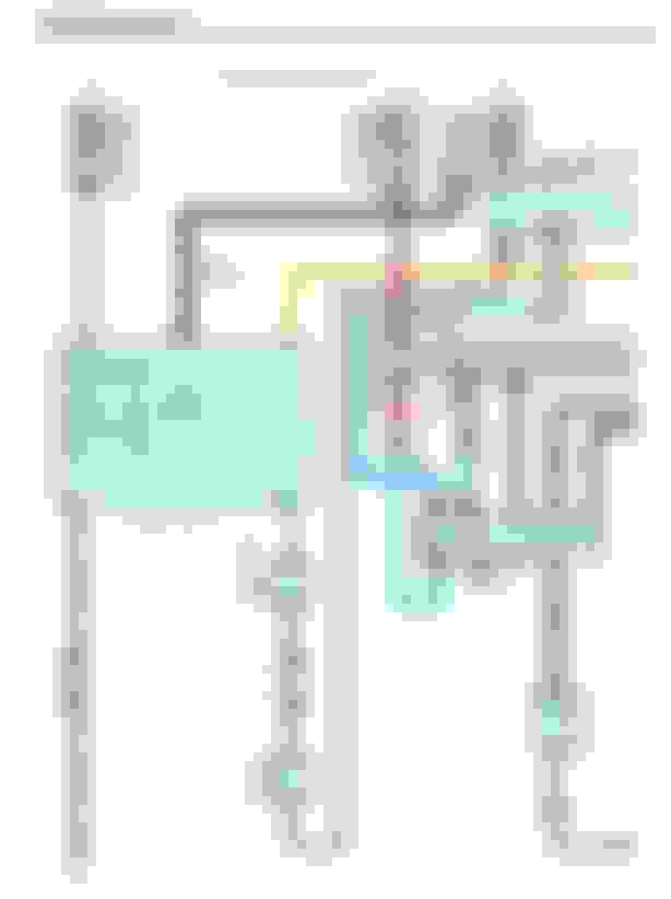
The first thing we should always do is look to see what the service manual wiring diagrams show. These are sometimes confusing, and should always be verified that you understood it correctly before starting your mod.
In the above diagram, it reads that that the 12V source will come from the 7.5A dome light fuse. This leads to a junction connector which connections multiple circuits together that will also feed off this source.
This 12V source then will go through the foot lights. Looking at the lower junction connector you can see that the two foot lamps connected directly together and output and end up on just one wire (marked B on the bottom junction connector.) From there that wire goes to the Passenger Side Junction Box ECU to a signal labeled "FSPT".
So what can we determine from this diagram?
Because the 12V is always sourced to the foot lights from the 7.5A dome fuse circuit and the return from the lamps go to the ECU, this lamp must be switched on/off in the ECU by connecting the return to ground.
If you looked further in the diagrams, you would find that the 7.5A dome is always "hot", even if the car is off.
We also can determine that there is only one return line for both footlights. This will be important in a bit.
But first, let's confirm that it works like we think it does.
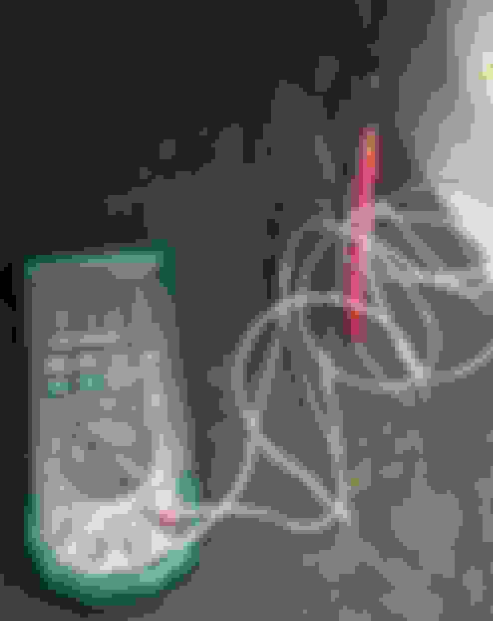
So the first thing we do is take a multimeter out to the car, gain access to the lamp socket. Here I pushed my meter leads into the two contacts in the socket and set the multimeter to read voltage. What I am doing here is to confirm polarity (which contact is positive, which is negative) and the voltage. I did this with the door open so that the foot light would be on. The key is not in the ignition.
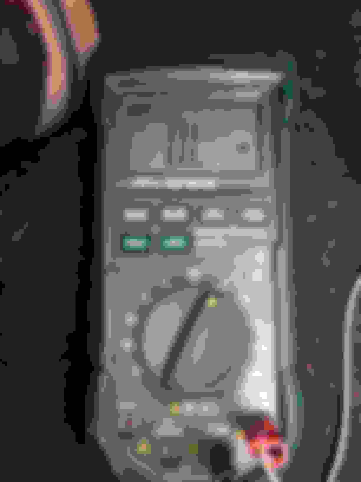
Our meter reads 12.23V. If we had the leads reversed, it would read -12.23v. So this indicates that the contact touching the read lead is the positive wire. Which is purple (note that this matches the wiring diagram above - the 12V from the dome fuse is indeed purple.)
To check whether the 12V or the chassis ground (return side) is switched, I performed the following steps.
I located some bare metal (unpainted) that was convenient. In this case, it is the radio bracket for me since I have some trim out right now for another reason.
I left my red lead attached to the lamp socket, and took my black lead and touched it to the bare metal.
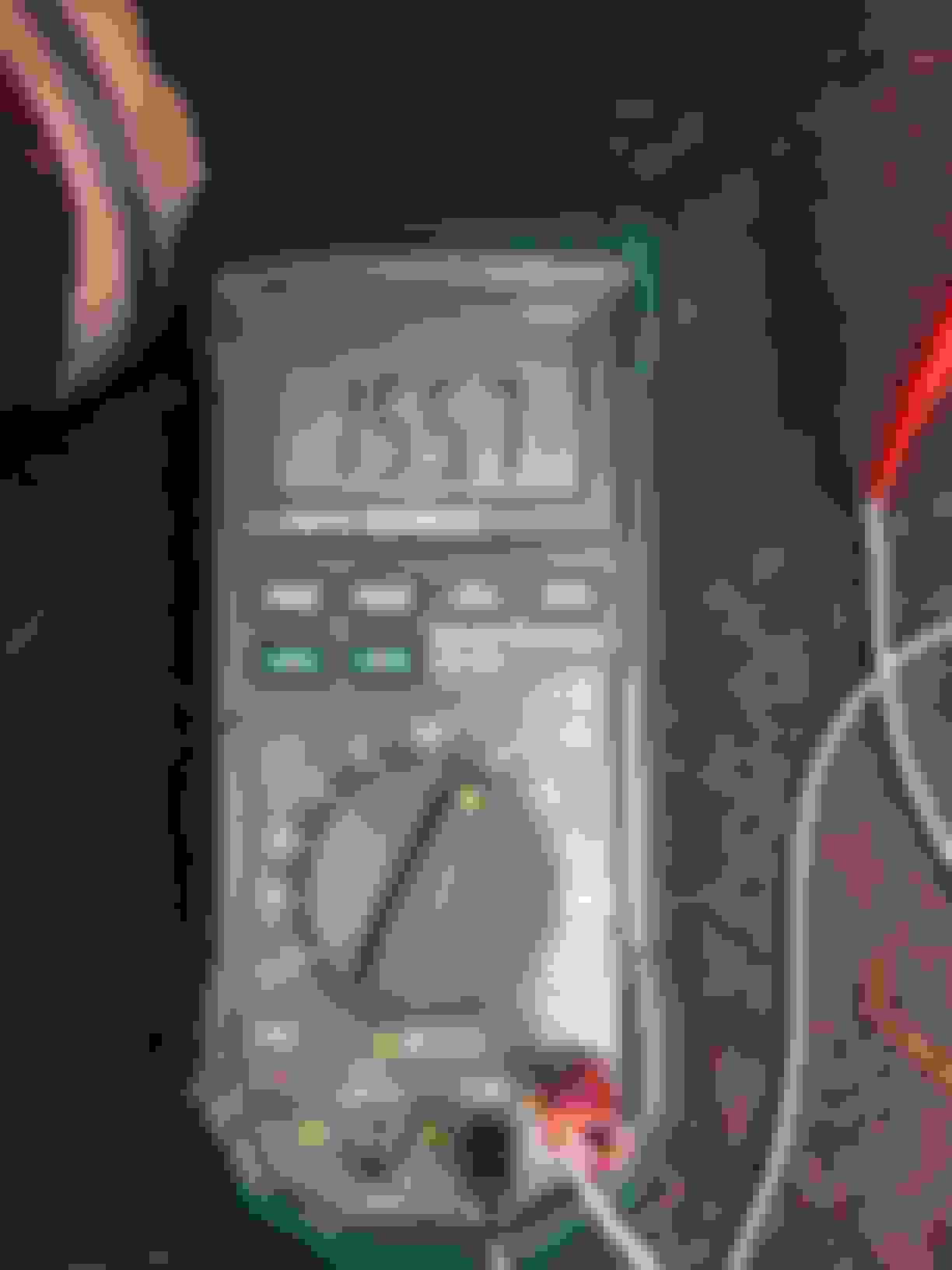
I now closed the door and waited for the dome lamp to go out. The meter still reads 12.36V. This confirms that the 12V is always 'hot' even when the car is off.
One last check...
For this check, I want to confirm that the chassis ground (return) is disconnected when the lamp is off.
I switched the multimeter to resistance mode. Many meters have a mode that will buzz when there is a short. On this meter, it is the next clockwise setting. But I am using the resistance mode because I want to make sure that the connection is completely 'open' (disconnected.)
I now moved my red lead to the return contact. In this case this is the blue wire in the amp socket. I have my black lead still touching the bare metal.
With the door closed and the foot lamp off, the meter reads, "O.L" which means Overload. That means the resistance is so high that the meter cannot read it. In other words, the return has been completely disconnected from the chassis ground.
At this point, an experienced person would have the confirmation they need. But let's do one more test for the sake of this tutorial.
Not changing anything (settings or location of the leads), I opened the door.
The meter now reads 155.7 (that little symbol means Ohms.) Just for an ounce of extra trivia, this tells me that it is switched by a transistor in the ECU. A transistor will always have some "ON Resistance." If it were a really, it would be very very small (only the resistance of the wires.) This is why I did not use the buzzer mode. Most buzzers will only buzz when the resistance is less than 50 ohms. I never would have gotten a buzz if I had been in that mode.
That's it for this tip. I will next show how to add a manual switch to a circuit like this and also discuss what would be different if the 12V had been switched instead.
So we started with some tips showing you how to take measurements and read wiring diagrams.
Now we are going to look at some basic electrical wiring techniques and concepts.
If you recall, we have a set of foot lights which come on when the door is open and then turn off in approximately 30 seconds. What we would like to do is be able to manually turn on the foot lights whenever we want.
First, I simplified the above wiring diagram so it will be easier to read:
The FSPT switch in that diagram is the Passenger Side J/B ECU. It is controlled by the vehicle. Notice that both lamps are controlled together.
Let's take a stab at implementing our idea.
Here we added a simple switch (SPST) that connects the light to chassis ground, bypassing the ECU. This is called a Logic OR, meaning switch one OR switch two is TRUE.
This configuration would work, but it would turn on both foot lights. It would also drain your battery if you forgot and left the switch on. Remember that the dome light fuse is always HOT.
So, let's say we want to turn on only the passenger side:
Here we replaced the simple (SPST) switch with a DPDT Switch. We had to cut the blue wire going to the lamp and wire it into our switch. When our manual switch is off, the passenger foot light is controlled by the vehicle. When we turn the switch on, only the passenger side foot lamp will come on. We are getting closer. This configuration would still drain your battery if you left the switch on. If you are not a forgetful person, this configuration would be fine. If you are not a forgetful person and you don't care that both lights come on, you could use the simple SPST switched circuit. That is the simplest of mods.
But let's say that we want to control only the passenger side foot light, and if we have it manually on, we want it to turn off when the car is not on.
Using the same DPDT switch, we just changed the wiring around. This time, we had to cut both the blue and the purple wires and wire them in to the switch.
This is a bit more complicated because now you also need to find a source that is switched with the ACC.
You could go one step further even, and instead of connecting to an ACC source, you could find an IGN source. This would be HOT whenever the key is in the ignition even if it is in the OFF position. However, this signal is a bit more rare in the car and would require finding a source further way (mostly in the driver side dash area.)
SPST = Single Pole Single Throw (Simple switch)
DPDT = Dual Pole Dual Throw (Two isolated circuits switched at the same time)
SPDT = Single Pole Dual Throw (one source can be switched between two circuits. It would look like one half of the DPDT above)
That was a lot to write and probably a lot to digest in one sitting. So I will follow up later with How we would handle it if the 12V side had been switched.
Trying to do these in an order of growing complexity. If there are any terms or concepts that I skipped over too quickly, please let me know and feel free to ask questions. Let's just be careful not to take over the thread too much with them.
Last edited by Retroplay; Jan 9, 2016 at 10:22 AM.
OR is a bit obvious. One input OR the other must be true for the output to be true.
AND means both inputs must be true for the output to be true.
XOR (Exclusive OR) is a bit more complicated. It means one input OR the other must be true, but not both.
1 = true (ON state)
0 = false (OFF state)
XOR looks like this:
1 + 1 = 0
1 + 0 = 1
0 + 1 = 1
0 + 0 = 0
Different project goals will require you to understand these concepts in order to achieve the desired results.
There are, of course, other logic types, but these are the basics. I recommend the link above.
If you have a casual interest in learning electronics but only enough for a weekend hobby, I would suggest the book, "Practical Electronics For Inventors." Even with my education, I keep a copy of it on my desk for reference and refreshing my knowledge. It is simple to read and it assumes you know nothing to begin with and offers projects and concepts that build on what you have learned.