Inner CV Boot repalcement DIY (FWD)
#1
Moderator

Thread Starter
This post is place holder for the upcoming DIY. I just used the title right now as I dont know how to edit it later.
Folks you have option to get new shafts. OEM are going to be expensive. Reman and aftermarket are reasonably priced. I prefer keeping OEM and dont mind the spending time fixing it.
Does any one remember the socket size for front drive shaft (also referred to as spindle nut). Is it 30mm?
Salim
Folks you have option to get new shafts. OEM are going to be expensive. Reman and aftermarket are reasonably priced. I prefer keeping OEM and dont mind the spending time fixing it.
Does any one remember the socket size for front drive shaft (also referred to as spindle nut). Is it 30mm?
Salim
Last edited by salimshah; 09-13-14 at 08:46 PM.
#3
Moderator

Thread Starter
Standard disclaimer:
Working with raised vehicles can be dangerous. Exercise caution!
This DIY involves parts that are involved with drive, steering, stopping and suspension. All these functions are important for safe driving. It also involves parts that store energy and proper care (eye protection) is a must.
Only try to do this DIY if you are competent to do so, else take your vehicle to a mechanic. If you choose to follow some or all of the instructions, you are doing it at your own risk.
Preventing damage:
Abs sensor, sensor wires and magnetic ring (tone ring) are delicate parts. Thread of the shaft end and the stud of the rod ends can get damaged. Protect them by keeping their nuts on them.
Parts and tools needed:
Inner boot kit
Floor jack - jack stands.
Torque wrenches
Sockets: 10, 17, 30 mm
Flat head screw driver and hammer.
Ratchet drives and extensions
8mm hex-Allen Key (socket kind is required)
Marker
Tie rod end separator
Rubber mallet
Breaker bar
Assistant for brief amount of time.
Pliers
split pins
Ring Pliers (not the snap ring) [Craftsman Item # 00947386000P Model # 47386 or equiv]
Plenty of rags
Gloves
Safety glasses.
Bench wise can be very handy.
Brake disc cleaner (you will have grease prints on the rotor)
You will need 4 nuts (sorry the size escapes me, I have box full of mm-size nuts and long bolts, nuts and washers. You can see that in the pictures later)
About 3 hrs of time.
Step by Step:
1. Park the vehicle on a flat surface (important). Chock 3 wheels that are not going to be raised.
2. Loosen lug nuts.
3. Jack up the side [for this DIY, it is the Driver Front] and remove the lug nuts and the wheel.
4. Remove ABS sensor, un-clip from pillar and tuck it away.
Loosen things up before dis-assembling anything. Leaving things in place will make your task easy.
5. Remove the split pin holding the spindle nut lock. Remove the lock.
6. Ask the assistant to apply brakes. Loosen the spindle nut couple of turns.
7. Remove the apron by removing 2 bolts.
8. Ask the assistant to apply brakes and loosen the Allen bolts of the inner CV joint. Bolts from 8 O'clock to 1 O' clock are easy. Do not attempt to undo any bolt from 2 O' clock to 7 O' clock as most likely you will slip and round them off. The drive shaft bends downwards and the bolt in 6 O'clock position does not have a straight access. There is more room in the front to manipulate tools. [For the passenger side the hr references would be reversed]
9. Do not start the RX, turn the ignition to ON, apply brakes and shift the gear to N.
10. Spin the rotor (that will turn the cv-joint) clockwise so the bolts between 2 and 7 move over to the easy access area.
11. Shift the gear to P and remove the key from ignition.
12. Loosen the remaining bolts from the cv joint.
At this time you may like to remove one bolt completely and run out to a hardware store to purchase 4 nuts.
It is very important that you have something to secure the joint once opened up. If the joint opens up, you will have a hard time to put it together and believe me it is counter intuitive to put it together properly. You assemble it wrong and it would not flex.
13. Loosen the lower control arm attachment point (lower ball joint) by loosening 1 bolt and 2 nuts. [do not separate the lower ball joint itself].
14. Remove the split pin of tie-rod end and loosen the nut. [Keep the nut on the stud].
15. Use the tie rod end separator to separate the tie rod end. Then take the nut off. Pull the stud out and put back the nut to protect the threads.
16. Loosen the spindle nut all the way to the end. Use a mallet to slide the shaft in (mine did not need any coaxing).
17. Remove the 2 nuts and 1 bolt of the lower ball joint assembly and push down the lower control arm freeing the rotor assembly.
18. Remove the spindle nut and pull out the rotor assembly to get the shaft out of the rotor assembly. Put back the spindle nut on the end of the shaft to protect the threads. Some folks at this stage would suggest removing the 2 lower bolts of the front shock absorber. I found it was not needed.
Since my objective is to replace the boot, I chose not to pull out the shaft from the transmission.
19. Mark the cv joint portions so that the shaft goes back the same way on assembly.
20. Remove the six Allen bolts and gingerly remove the shaft. [passenger side has few more steps].
21. Immediately put 4 nut & bolts and crescent washers to secure the joint. Cradle side to the outside. Hand tight nuts and bolt.
22. Clamp the shaft on a wise bench.
23. Mark the tip of the shaft with the innards of the CV joint, Idea is that once you pull the shaft out, on assembly you will reengage the shaft at the same location.
24. Clip the old bands.
25. With the lock ring pliers remove the lock ring. [remember to put on eye protection]
26. Pull the CV joint off the shaft.
27. Pull the boot off the cup and off the shaft [the boot was in two pieces for me]
28. Clean off some old grease and pack new grease on the boot side.
I decided not to replace the cup as the old one had no issues.
29. Slightly grease the lips of the boot and push the new boot on the cup.
30. Slightly grease the smaller end of the boot. Slide the shaft through the smaller hole.
31. Feed the shaft through the CV joint and twist to match the marks. Verify, the marks match as the shaft comes out. Pull back and twist and then reinsert and verify.
32. Once the marks match use the lock ring pliers to install the new lock ring. [safety glasses]
33. Install the new band rings. There is a ridge on the band where the other side of the band (after wrapping around) has a place to rest. Then you apply leverage (keep wrapping) and the band starts squeezing the boot, till it comes flat. Use a dull flat object (old screw driver) to fold over the tabs. Use a hammer to beat down the clamps to secure it.
34. Ensure the smaller end is at the right spot on the shaft and put in the smaller clamp.
35. Fill fresh grease on the lock ring side of the CV joint. Use the remaining grease to fill the portion of the CV joint which is still attached to the transmission.
Testing:
Try flexing the shaft while holding the cv joint.. It should bend in all directions. Gently pull in out the inner cv joint. Limit the travel to 1/2". If you over pull the joint can come apart.
Next step is putting the shaft back.
36. Remove the 4 bolts that you put in at step 21.
37 Match the mark and temporarily put 2 Allen bolts in ... you can skip the crescent washer at this step . The shaft is wiggly and the intent is to get it in place.
38 Put in the other 4 bolts with the crescent washers. Take off the two bolts (step 37) and now put in the crescent washers. All 6 bolts should be hand tightened. Verify the marks match. If not undo the bolts and twist the shaft and repeat 37 & 38. Again we are not tightening the thing down just yet.
39. Remove the nut from the shaft end and swing out the rotor and stick the shaft through the center hole. Put the nut on the shaft ... just couple of threads for now.
40. Reattach the 2 nuts and 1 bolt of the lower ball joint assembly. You may have to shake the assembly so that the nuts and bolts seat correctly. This why we want to keep every thing loose till this time.
42. Undo the tie rod end nut and pass it through the knuckle hole and put the nut back on and hand tighten it.
43. Now go back and start torquing down the 6 cv joint allen bolts. Do the 8 O'clock to 2 O'clock first. Then do the same trick [step 8 to 11] till you have all 6 torqued to 48lb-ft. I did not need an assistant for this step.
44. Torque the lower ball joint assembly 2 nuts and 1 bolt 94lb-ft
45. Torque down the tie-rod end 36lb-ft. Put in a fresh split pin. I had to overtighten by 1/16 of turn to pass the pin through.
46.Thread back the ABS sensor (dont forget to clip it on the pillar) and toque down the holding bolt to 71-in-Lb
47. Ask the assistant to apply brakes and toque down the spindle nut to 217 lb-ft.
48. Put on the lock nut and put in a fresh split pin. Switch around the position of the lock nut till you have a clear access for the split pin.
49. Use the brake cleaner to clean the rotor.
50, Put the apron back.
Do a visual. Make sure the shaft has not been pulled out of the transmission. Look for leaks and boots in stress.
Put on the wheel. Torque the lug nuts to 76 lb-ft.
Test:
Push the driver end of RX up and down and make sure the vehicle moves smoothly.
Put the veh in "N" and push the vehicle for at two wheel revolutions going backwords and forwards.
Once those 2 tests pass, take your RX for a short spin. If you fail the above test, time to redo the whole thing or look for mobile mechanic.
Salim
pictures to follow.
Last edited by salimshah; 09-28-14 at 09:30 AM.
#4
Moderator

Thread Starter
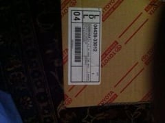
Boot Kit
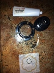
Boot Kit contents
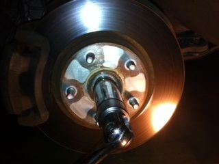
Unthreading Spindle Nut
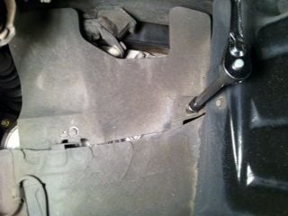
Upside down pic of apron
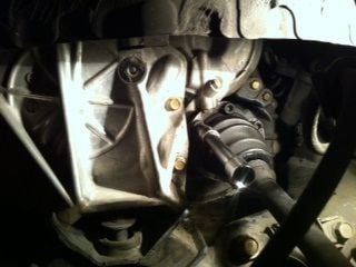
Allen bolt at 10 O'clock (easy access)
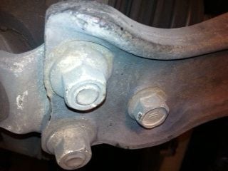
Lower ball joint assembly 1 bolt 2 nuts (picture from below)
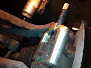
Tie Rod end separator. Note the loosened nut is still on. (picture is upside down)
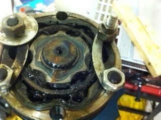
Crescent washers holding the CV joint together. Note the mark I scribed on the shaft and the innards.
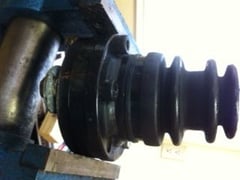
New boot on the old cup. Dont do this without the nuts, bolts and crescent washer in place.
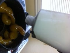
Greasing of the CV joint (This is before the boot is put on the cup).
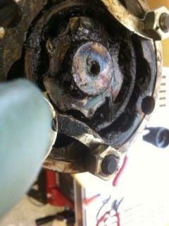
Shaft back in place and the ring is in place. Marks are matched up. About to grease the inside.
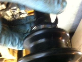
Clamp in place and I am about the apply the leverage. Not the best photo but you get the picture.
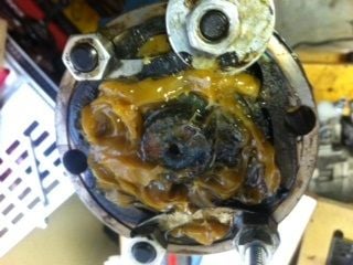
Mix of old and new grease.
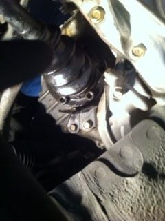
Upside down picture with 2 temporary bolts in place
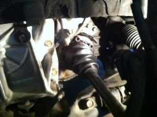
With the crescent washers in place
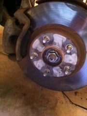
Spindle nut back on
Salim
Last edited by salimshah; 09-13-14 at 10:22 PM.
#6
Moderator

Thread Starter
Testing:
Try flexing the shaft while holding the cv joint.. It should bend in all directions. Gently pull in out the inner cv joint. Limit the travel to 1/2". If you over pull the joint can come apart.
We are looking for the cv joint to flex in all direction and the length should be able to extend or contract with smooth action.
This DIY only fixes a torn boot and lost grease. If the joint is worn out ... clunking, then replace the joint/shaft. Once the boot is torn, you will loose the grease, Once the grease is lost, the joint (metal to metal rub) gets worn. Once the metal wears, the clunk is metal to metal banging. The old proverb, stitch in time saves nine applies here.
Salim
Last edited by salimshah; 10-26-14 at 07:17 PM.
Trending Topics
#8
Moderator

Thread Starter
Bounce: Confirms the axle can flex.
Roll: Confirms cv joint is working.
Either test fails, indicates there is a lockup. If you dont check then the torque from the engine will cause serious damage.
Salim
Thread
Thread Starter
Forum
Replies
Last Post
Organized Garage Status
ES - 1st to 4th Gen (1990-2006)
0
03-14-18 10:53 AM


