When you click on links to various merchants on this site and make a purchase, this can result in this site earning a commission. Affiliate programs and affiliations include, but are not limited to, the eBay Partner Network.
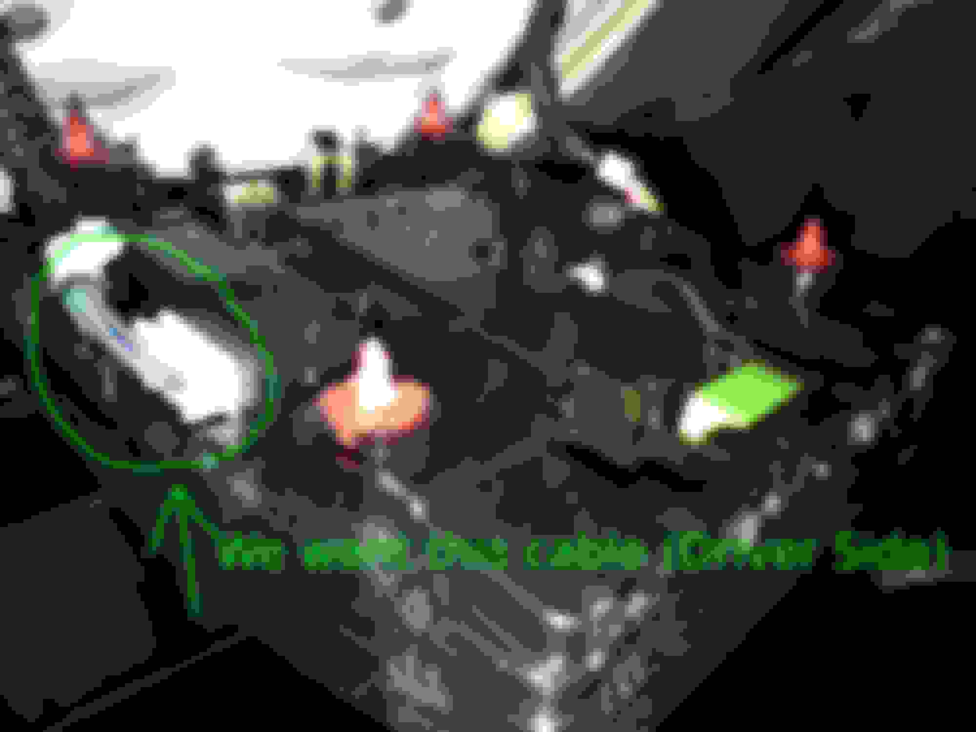
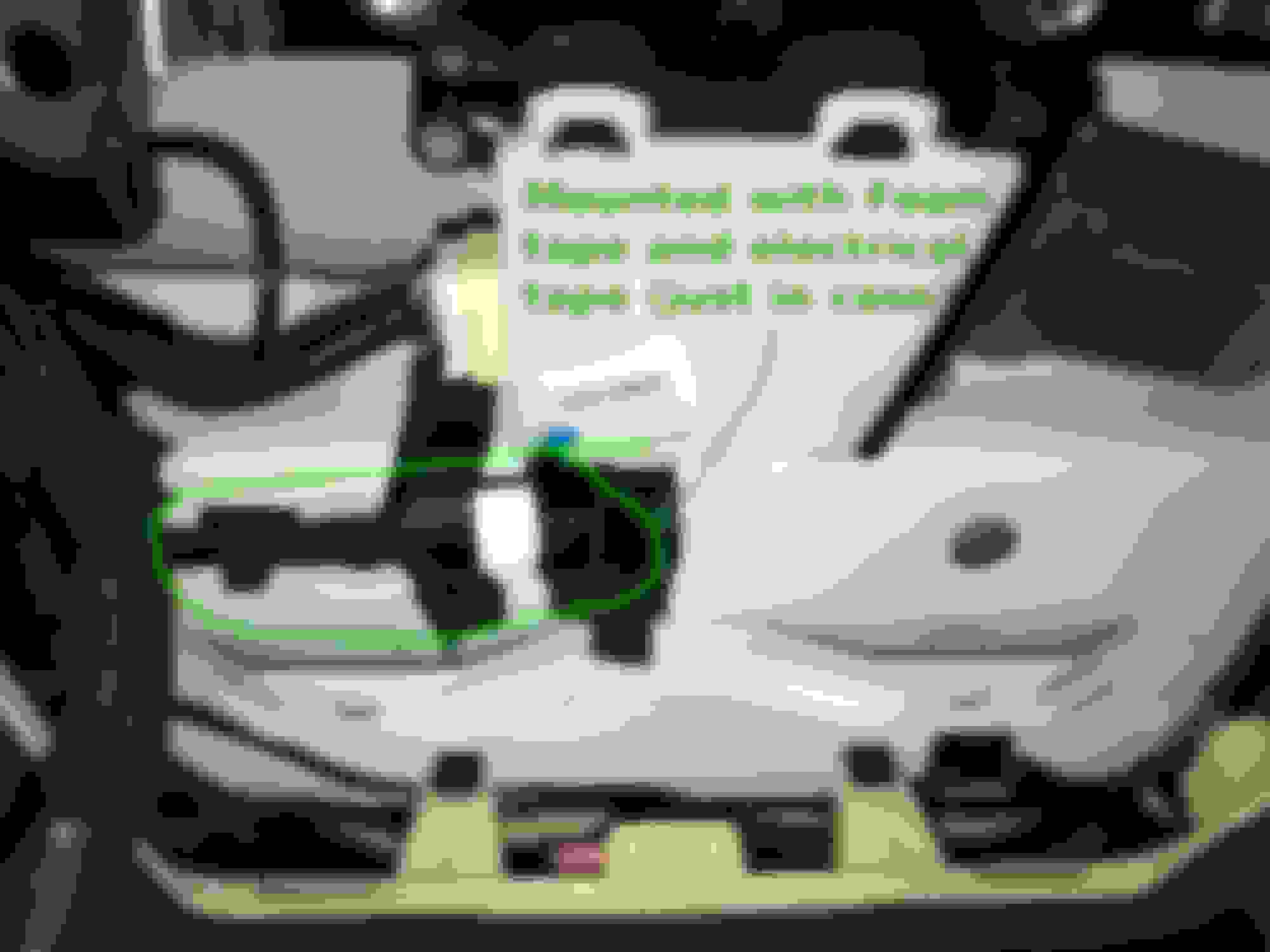
I have an RC 350 and wanted to install a dash cam but didn't want to run the wire down the pillar and into the cigarette lighter (because that wouldn't be much of clean looking install,) and I wanted to do something different than the mirror tap (for radar detectors) I've seen people do online. I first removed the map light with a plastic pry tool that came with my dash cam. The map light is held by 4 red plastic anchors. Just pry around the map light while gently pulling with your other hand and it should come off no problem.
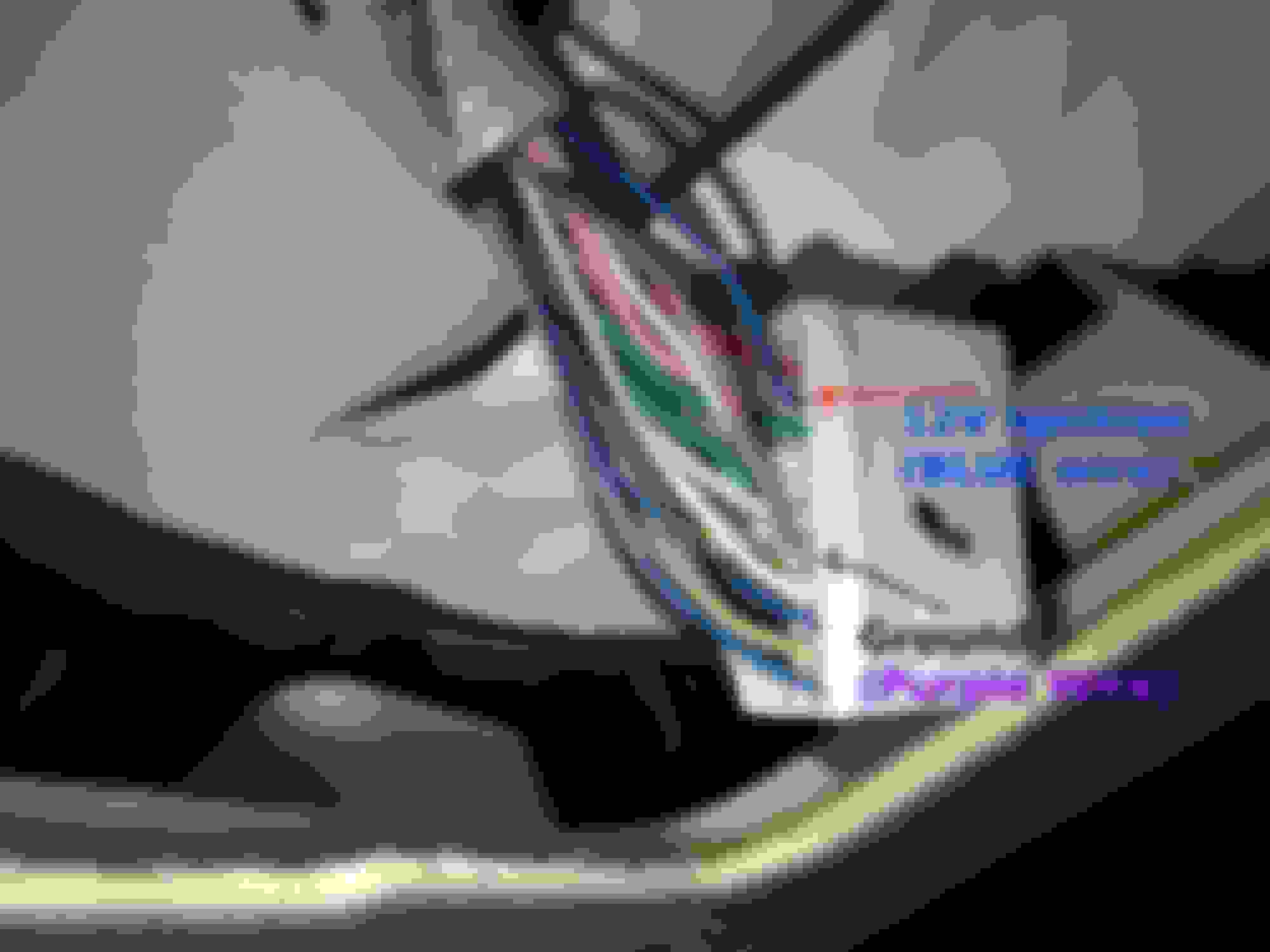
We want to use the connector by the driver side and tap into a couple of those wires.
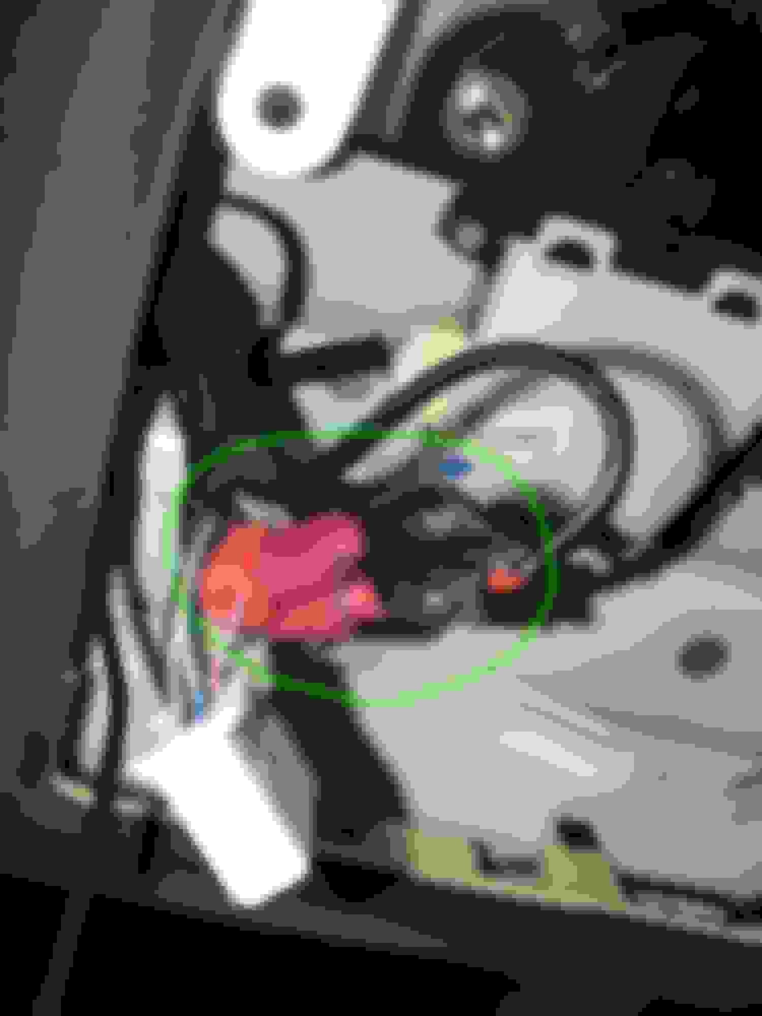
Add T-Taps to the specific blue and purple wire, then get some heavy duty pliers and squeeze the T-Tap to make sure they pierce the wire properly.
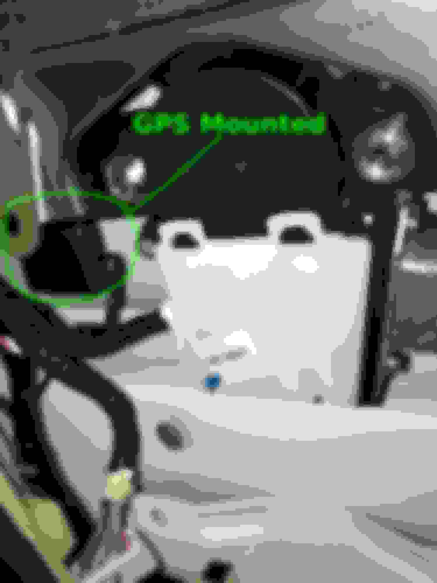
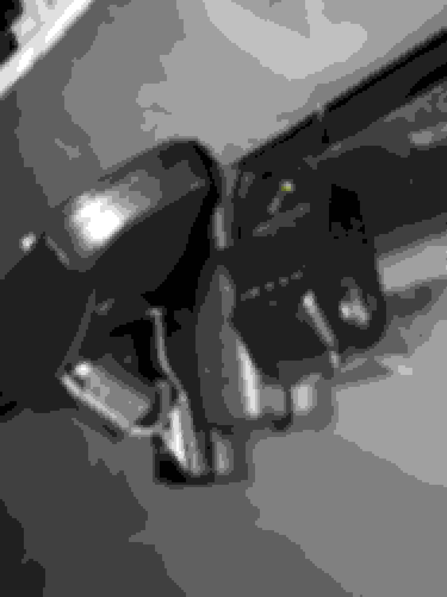
There's plenty of room here, so I installed the GPS there with the provided double sided foam tape from the Dash cam.
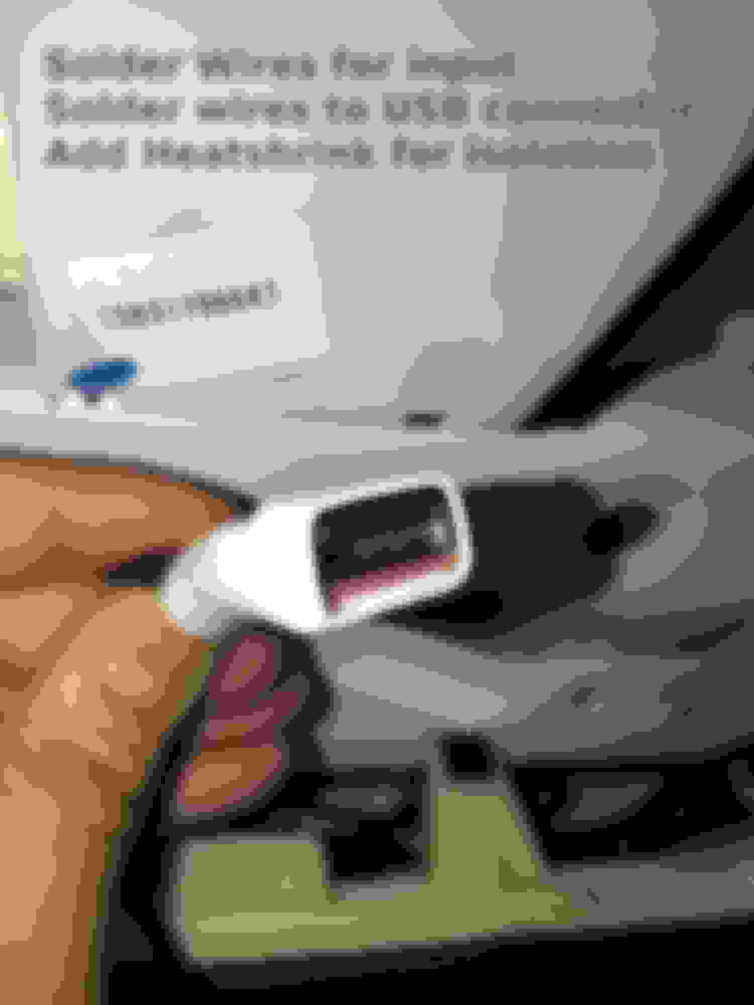
I soldered a couple wires to the DC-DC Buck Converter on the input side that would feed out to the 12V ignition wire and ground of the vehicle. I then cut an existing USB cable I had lying around and soldered the 5V & Ground under the USB connector to the DC-DC Buck Converter. I then added 1" shrink tube for isolation purposes to the entire DC-DC Buck Converter. Now my USB connector of the DC-DC Buck Converter is free for me to add any other USB device in the future. I dont know what I would add lol, but it's free for me to use hahaa.
Mounted the DC-DC Buck Converter here and ran the usb connector to the dash cam and GPS wire out to the right side of the rear view mirror:
Connected the input wires of the DC-DC Buck Converter to the T-Taps. **Remember, Blue = 12V Ignition wire (only powers on once the car is on), and Purple is the ground **
Install the car's connectors back into the map light and line up the 4 red plastic anchors and gently push the map light back in place. Connect the wires to the cam, and power on the car (forgot to take a picture with the USB connector). Done!
Most of the work is me probing around trying to find which wires I needed to tap into. Took me about half an hour because my probes were too fat for the connectors, but I eventually stripped some twisty ties to my probes to get what I needed. I choose a DC-DC Buck converter because it should produce less heat compared to a linear voltage regulator. So far I'm happy with the install and just felt like doing something a bit different.
I went with the DR650s-2Ch system. I just ran the wires from the camera, through the windshield panels, down my drivers side door panels and wired it directly into my fuse box. I fed the wires for my rear camera in a similar way, just running from the passenger side panels, all the way to the back. I see you are using a different camera though, how is the quality?
I went with the DR650s-2Ch system. I just ran the wires from the camera, through the windshield panels, down my drivers side door panels and wired it directly into my fuse box. I fed the wires for my rear camera in a similar way, just running from the passenger side panels, all the way to the back. I see you are using a different camera though, how is the quality?
Quality is surprisingly really good! I wanted a discrete dash cam that had a capacitor (for power stability instead of the small lithium ion batteries in other cams for startup/shutdown) issues that I read occur in hot areas.
On a side note, I also realized that a person can also use the T-Taps on the wires i've labeled (at least for the RC 350) for a radar detector as well.
I went with the DR650s-2Ch system. I just ran the wires from the camera, through the windshield panels, down my drivers side door panels and wired it directly into my fuse box. I fed the wires for my rear camera in a similar way, just running from the passenger side panels, all the way to the back. I see you are using a different camera though, how is the quality?
Where did you plug yours in on the fuse box? My friend said plug it into one that says "15A." I know nothing about cars and have been pulling my hair out trying to figure out how to hard wire my Dashcam to the fuse box ☹️
I didn't tap into the fuse box. I took the 12v line that powers on only after the car is turned on (the blue wire in this case) then used a cheap Step Down Converter to converter the 12v into 5v and then into the dash cam using a usb to micro usb cable. the 3.5mm headphone jack you see is from the GPS module that came with the Dash Cam
I didn't tap into the fuse box. I took the 12v line that powers on only after the car is turned on (the blue wire in this case) then used a cheap Step Down Converter to converter the 12v into 5v and then into the dash cam using a usb to micro usb cable. the 3.5mm headphone jack you see is from the GPS module that came with the Dash Cam
Jay-
I'm hoping you can help me out a bit. Since my car is a different year/model (2014 ES300h) I'm assuming my colored wires are different than yours (blue & purple). Can you tell me how you were able to track down your ground wire (your purple wire). Did you check for continuity with another "known ground" somewhere? If so, where? - - I assume you used a ground you found and probed the other wires looking for 12+ volts on your multimeter. Is that right?
Also, when you probed your wires did you use "back probing" or did you probe through the front of the wire harness somehow? I know once I get the wires identified I'll be home free. - - Thanks for any help you can provide me.
Dave
Finding the ground wire is super easy and is done with the ignition off. have one probe from your multimeter touching a solid ground point on the vehicle (typically non painted surface) and the other probe of your meter will hunt for the corresponding ground wire on the harness. Yes, i touched the back of the connector because it was easier fro me since my probes were kinda fat and couldn't fit in the front of the probe, but you could always strip a thin metal wire to your probe in a pinch to touch the front of the connector if you want.
Once you have identified the ground wire, turn the ignition on. Now have one probe touching the ground wire you found, and have the other probe looking for 12V. In my vehicle, there were a couple potential 12V wires I could use. I wrote down all potential 12V wires and turned off the vehicle again.
WIth the vehicle off, one of the 12V wires continued to supply power to the wire. I assume that if I had used this specific 12V wire, then the camera could potentially continue to be on even when I turned off the vehicle, but I didn't want to drain my battery in the long run so I decided not to go with this 12V wire. Instead, I choose the 12V wire that only powered on when the ignition was turned on.
You can't really mess anything up, so be patient and you'll find the wires that you need. A lot simpler, easier, and cooler (in my opinion at least) to do than the fuse tap everyone else tends to do to get 12V to some sort of device.
Jay-
Thanks for your reply!
I messed with it again before your reply came in and essentially did what you suggested. I used the bottom rim of the cigarette lighter in the console for my “known ground” and then was able to find a ground in the left-side wire harness… it’s white w/ black stripe. (6th wire) Funny enough, there were 2 similar colored wires just before that one that didn’t test positive (for negative) on the continuity test… ?
Then I continued to use the cigarette lighter ground to find the “ignition positive”… a light-brown wire on the other side of the harness (1st pin). By the way I inserted a little needle in the front part of the harness to test each wire; that seemed to do the trick. It’s a little tedious, but there are only 12 wires on each side…
The light-brown wire would be easy to tap into as it’s on the end, but the white w/ black wire is really jammed into the pack of wires which would make it a bit harder to hook my positap onto. - - I’m going to see if I can find a pair of wires on the right side harness to use instead as there are only about 12 wires over there making it much less crowded and easier to hook up the Positap connectors. - - I believe someone said that the left wire harness needs to be plugged-in to test the wires on the right harness, so I’ll try doing that.
Thanks again Jay very much for your reply. I’ll keep you posted.
Nice quality pics! I hear ya with fat probes. With my Fluke multimeter, I use the alligator clip leads and grab paper clips or even sewing needles/pins to probe close spacing between electrical pins inside of connector housings.
Since I have been rear-ended twice with my old G37 couple, and not my RC, I would appreciate a rear-view camera.
I messed with it again before your reply came in and essentially did what you suggested. I used the bottom rim of the cigarette lighter in the console for my �known ground� and then was able to find a ground in the left-side wire harness� it�s white w/ black stripe. (6th wire) Funny enough, there were 2 similar colored wires just before that one that didn�t test positive (for negative) on the continuity test� ?
Then I continued to use the cigarette lighter ground to find the �ignition positive�� a light-brown wire on the other side of the harness (1st pin). By the way I inserted a little needle in the front part of the harness to test each wire; that seemed to do the trick. It�s a little tedious, but there are only 12 wires on each side�
The light-brown wire would be easy to tap into as it�s on the end, but the white w/ black wire is really jammed into the pack of wires which would make it a bit harder to hook my positap onto. - - I�m going to see if I can find a pair of wires on the right side harness to use instead as there are only about 12 wires over there making it much less crowded and easier to hook up the Positap connectors. - - I believe someone said that the left wire harness needs to be plugged-in to test the wires on the right harness, so I�ll try doing that.
Thanks again Jay very much for your reply. I�ll keep you posted.
Jay-
Well, it all worked out! I did find a white & black stripe wire on the right side (ground wire) and a blue wire (ignition positive). I didn't bother plugging in the left-side wire harness when searching for the wires on the right-side harness because as I looked everything over, that idea made no sense to me. It turns out, I didn't need to do that.
Thanks again for your great explanation and as greasefin said, "your great pics"! It's very nice that you shared all that info and that you're still around a year later!!! Thanks again very much!!!
Originally Posted by greasefin
Nice quality pics! I hear ya with fat probes. With my Fluke multimeter, I use the alligator clip leads and grab paper clips or even sewing needles/pins to probe close spacing between electrical pins inside of connector housings.
Since I have been rear-ended twice with my old G37 couple, and not my RC, I would appreciate a rear-view camera.
Yeah greasefin, I too used some sewing pins... they worked fine! So far I only have the front dashcam... I know the rear one would impact the window tint for sure...probably not a big deal... plus, I'm trying to keep my dash cam kind of stealth...lol... I have it up by the humidiity checker, rain checker & rear view mirror. It's kind of hard to see and looks like it just belongs there. I'm not sure how I'd have a stealth rear dash cam...
I know what you mean about getting rear-ended. I kind of half-joke that I pay as much attention to the car behind me as I do to the car in front of me! It's actually not really a joke; - - I don't let anyone just camp-out on my rear as they drive because when they can't stop it's me who will pay the price!
My dashcam simply needed an OBD port....runs anytime there is movement by the car. These cams did not have that option?
Many current dash cams offer "park mode" where movement and or/bumps to your car are detected; mine doesn't have that, but it does have a setting that locks video footage of any jolts to your car while driving. I'm not sure how useful that feature would be.
I'm pretty sure most all of the dash cams with "park mode" have some sort of limiting device so that you don't inadvertently run down your car battery. - - I personally opted for getting power from above the windshield rather than grabbing the power under the dash with an obd port. I didn't want to hassle with winding wires up through the pillars, etc... Luckily, there are lots of options available to install our dash cams.
 08-06-17, 01:10 PM