When you click on links to various merchants on this site and make a purchase, this can result in this site earning a commission. Affiliate programs and affiliations include, but are not limited to, the eBay Partner Network.
Wiring diagrams are pictured as if you're looking at the ecu (pins coming out). If you're looking at the back of the wiring harness (side with wires coming out), then its the same as the diagrams and pin 1 is top right.
If you're looking at the female side of the plug (the one with all the holes), then pin 1 will be top left.
Originally Posted by gerrb
Ed - whenever you are dealing with our Lexus SC wiring , regardless of which one in our cars ... hold on any connector facing you meaning pins in front of you with the lock tab on top and wires behind . Number one (#1) pin will be the top left most ... then go to the right most counting ... then go to the next row continue counting left to right till you get to the pin number you are after . That will be the easiest way to find which pin you are looking for ... then just grab the wire behind for that particular pin .
You get the hang of counting those pins with the way I just mentioned , then it will eventually be easy as time pass.
ECU or component pinning will be the opposite .. Top Right is #1... then count going to left .. then next row .. right to left, till you get to the pin of the ECU or component that you are after .
I sincerely thank you both as I'm sitting here counting pins on my spare amp ECU connector and now see what you're talking about I think I was in row 30 something so I think car was running on just coil one so only cyl 1and 6 were firing lol. Now that I count the pins now I see to use 55 and 56 .. will re do hopefully later in the week right now gotta focus on hurricane Irma as it looks as of now we are a direct hit for cat 4/5 , yikes ����
Electrical guy I am not but learning fast. Mechanical guy is what I am
the pin numbers on the ecu connector can get confusing, have gotten the wrong number a few times myself before getting it down.
hopefully that should solve the issue.
Thanks for the good info Motorheaddown, reading some of your threads and posts is what convinced me to use the vvti coils over the TT ones. definitely glad I listened
the only difference between wiring these up to an AEM and a TT ecu is that you have to manually connect pins 52 and 57, 53 and 56, and 54 and 55. they are internally connected in the aem, for the TT ecu we have to manually connect them to run 3 sets of coilpacks in wasted spark. pretty simple and straight forward.
read the following thread. https://www.clublexus.com/forums/sc-...-odb1-sc3.html
just to confirm ali or gerrb ,
if im going to use pins 55 and 56 as opposed to 53 and 54 ( becuse my 53 and 54 already occupied , to what i do not know) pin 56 corresponds to pin 53 and pin 55 to pin 54 correct to make sure i have the coils pin out in correct order
what ecu are you using? aem v1? or v2?
You shouldn't have pins in 52-56 on a stock harness, if there is then you are looking at the wrong pins.
on a stock ge harness, the stock coil is on 57 and the IGF wire is on 58 (usually red/yellow color).
IF you have pins in 52-56 they have been added and you need to sort those out or remove them cause if they are connected to stuff you can short things out. having pins in 53 and 54 tells me someone added those to run vvti coils at some point. so remove or reuse those wires.
for v1 you can use 52-54 or you can use 55-57 with the settings on page 1 since companion cylinders are connected together inside the ecu.
So 56 and 53 are companion coils, 55 and 54 are companion coils, and 57 and 52 are companion coils.
Since the stock coil wire is in 57, I generally add the 2 new wires to 56 and 55 for vvti coils. in that case 52-54 should be blank as in no wires.
You could also mix and match by adding the 2 new wires to 53 and 54, so you would have pins in 53, 54 and the stock 57 which it sounds like someone did previously on that harness... but you can see how that can get confusing pretty quick.
Also really important is you change the crank settings to falling edge, set the coil phasing numbers properly where tooth 1 is 21.53 etc... (See page 1 verify numbers for all the tooths) and sync your timing with a light. if you don't do that especially the coil phasing numbers you will most likely have engine damage as in a failed piston causing lots of carnage in the block.
for V2 which has more coil drivers, you cannot just use whatever set you feel like with the same settings.
depending on which set you use, you need to setup those values in the aem to match cause those pins are not connected internally.
I wrote a guide specifically for the aem v2: https://www.clublexus.com/forums/per...-settings.html
you can see whatever ones you use coil 1-3 or coil 4-6, there is an option under each one for coil 1B, 2B, 3B, 4B.. etc...
so depending on which set you wire to, you fill in the numbers for 1-3 and 1B-3B, OR you fill in for 4-6 and 4B-6B.
the aem v2 installation guide tells you which pins go to what coil #'s, in the link above they are setup like this:
Wire coil 1 (cylinders 1 and 6) to pin 57B on ecu connector.
Wire coil 2 (cylinders 2 and 5) to pin 56B on ecu connector
Wire coil 3 (cylinders 3 and 4) to pin 55B on ecu connector.
And you have to put in the coil phasing numbers as shown in that thread to get it to work for 1-3 and 1b-3b.
Hi, I need some help setting up my vvti coils on the GE with aem ems S1. I cannot get it to start because it shows timing and sync errors. Stock distributor, for cps signal.
I have evrything wired up like for a TT ECU with vvti coils.
On my ECU pin out I have added 5 pins. Coil wire 1 and 6 together, 2 and 5, 3 and 4. So I spliced those wires by the ECU and ran 2 new wires to T2 and T3. I tried using the options you put up, But I'm still not getting spark. I am getting fuel. I have been working at this last three evenings with no luck. I'm getting annoyed.
see attached pic.
what ecu are you using? aem v1? or v2?
You shouldn't have pins in 52-56 on a stock harness, if there is then you are looking at the wrong pins.
on a stock ge harness, the stock coil is on 57 and the IGF wire is on 58 (usually red/yellow color).
IF you have pins in 52-56 they have been added and you need to sort those out or remove them cause if they are connected to stuff you can short things out. having pins in 53 and 54 tells me someone added those to run vvti coils at some point. so remove or reuse those wires.
for v1 you can use 52-54 or you can use 55-57 with the settings on page 1 since companion cylinders are connected together inside the ecu.
So 56 and 53 are companion coils, 55 and 54 are companion coils, and 57 and 52 are companion coils.
Since the stock coil wire is in 57, I generally add the 2 new wires to 56 and 55 for vvti coils. in that case 52-54 should be blank as in no wires.
You could also mix and match by adding the 2 new wires to 53 and 54, so you would have pins in 53, 54 and the stock 57 which it sounds like someone did previously on that harness... but you can see how that can get confusing pretty quick.
Also really important is you change the crank settings to falling edge, set the coil phasing numbers properly where tooth 1 is 21.53 etc... (See page 1 verify numbers for all the tooths) and sync your timing with a light. if you don't do that especially the coil phasing numbers you will most likely have engine damage as in a failed piston causing lots of carnage in the block.
for V2 which has more coil drivers, you cannot just use whatever set you feel like with the same settings.
depending on which set you use, you need to setup those values in the aem to match cause those pins are not connected internally.
I wrote a guide specifically for the aem v2: https://www.clublexus.com/forums/per...-settings.html
you can see whatever ones you use coil 1-3 or coil 4-6, there is an option under each one for coil 1B, 2B, 3B, 4B.. etc...
so depending on which set you wire to, you fill in the numbers for 1-3 and 1B-3B, OR you fill in for 4-6 and 4B-6B.
the aem v2 installation guide tells you which pins go to what coil #'s, in the link above they are setup like this:
Wire coil 1 (cylinders 1 and 6) to pin 57B on ecu connector.
Wire coil 2 (cylinders 2 and 5) to pin 56B on ecu connector
Wire coil 3 (cylinders 3 and 4) to pin 55B on ecu connector.
And you have to put in the coil phasing numbers as shown in that thread to get it to work for 1-3 and 1b-3b.
Morning Ali
I bought the car 10yrs ago from second owner completely stock , car was a virgin which is why I bought it .. I can't explain why those pins are occupied but ill check again tonight , its possible I was misreading pins , if not I don't know what those already pinned wires represent , remember mine is late model 97 and do have crank position sensor as well......I'm using aem v1
Hi, I need some help setting up my vvti coils on the GE with aem ems S1. I cannot get it to start because it shows timing and sync errors. Stock distributor, for cps signal.
I have evrything wired up like for a TT ECU with vvti coils.
On my ECU pin out I have added 5 pins. Coil wire 1 and 6 together, 2 and 5, 3 and 4. So I spliced those wires by the ECU and ran 2 new wires to T2 and T3. I tried using the options you put up, But I'm still not getting spark. I am getting fuel. I have been working at this last three evenings with no luck. I'm getting annoyed.
see attached pic.
un-check crank rising edge and it should work, leave falling edge checked. you should be getting stat synced to go to ON.
once stat sync is turning on, it should start and be sure to set your timing as soon as it starts, or if it wont start do it while cranking.
if you are not getting stat sync to come on then there is definitely an issue.
also make sure to set your throttle position cause its reading 15%, it should be 0 without your foot on it.
also change your map reading to psi, when I convert that to psi its like 13-14 psi which is close to right but it seems like the bar is maxed out.
make sure to setup the map sensor wizard for whatever map sensor you are using, that will have a big role in starting and running the motor when you have stat syncd on.
Originally Posted by lexforlife
Morning Ali
I bought the car 10yrs ago from second owner completely stock , car was a virgin which is why I bought it .. I can't explain why those pins are occupied but ill check again tonight , its possible I was misreading pins , if not I don't know what those already pinned wires represent , remember mine is late model 97 and do have crank position sensor as well......I'm using aem v1
I bought the car 10yrs ago from second owner completely stock , car was a virgin which is why I bought it .. I can't explain why those pins are occupied but ill check again tonight , its possible I was misreading pins , if not I don't know what those already pinned wires represent , remember mine is late model 97 and do have crank position sensor as well......I'm using aem v1
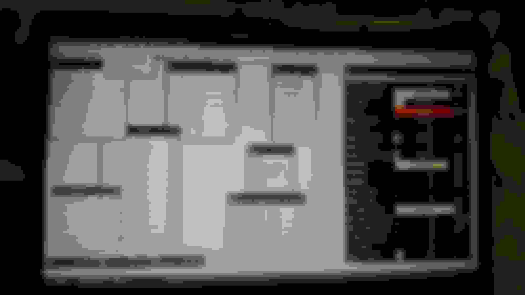
You might be looking at row 30 instead of 50. I highlighted 52-57.
Also forgot to mention:
omni/gm style 4 bar map sensor
ford 5.0 TB and ford TPS
I think I adjusted for 4 bar map. And maybe not.
i tried to crank with timing light last night. No spark. I saw that sync was on. Finished off with a gunshot sound from the engine lol. So called it a night. I think I need to pull fuel pump fuse and try to get ignition going.
also having coils active 1 2 3 and 6 7 8 right? I saw that on first page.
if you got stat syncd and a backfire sound then you might have had some ignition just the timing is way out.
maybe the timing is in pretty far off and the line is not showing up on the crank where it supposed to, look from the other side.
did you remove the distributor recently? also by correcting falling edge and the phasing numbers it throws the timing off quite a bit.
Thanks, I got it to start. And then it dies. But its because my ford Idle control valve is not connected. I will try crack open the TB a little and make some adjustments. Thanks for your help.
that should get it going, even with the iacv connected you usually have to play with the percentages to get it to idle the first time it is setup.
I would just crack it open some more like you said.
sometimes you have to mess with the fuel and ignition maps also to get a steady idle.
keep an eye on the map sensor readings and make sure its reading what it should be, if you have a vacuum/boost gauge that helps.
Ed - whenever you are dealing with our Lexus SC wiring , regardless of which one in our cars ... hold on any connector facing you meaning pins in front of you with the lock tab on top and wires behind . Number one (#1) pin will be the top left most ... then go to the right most counting ... then go to the next row continue counting left to right till you get to the pin number you are after . That will be the easiest way to find which pin you are looking for ... then just grab the wire behind for that particular pin .
You get the hang of counting those pins with the way I just mentioned , then it will eventually be easy as time pass.
ECU or component pinning will be the opposite .. Top Right is #1... then count going to left .. then next row .. right to left, till you get to the pin of the ECU or component that you are after .
hey gerrb , i am still abit confused as your instruction stataes count left to right going each row but when i count blxcoupe illustration it doesnt add up to where he has highlighted . can you elaborate
its the male side wires going into the connector. notice the tabs on the top, hold the connector just like that looking at the wire side.
Its the same numbering as gerrb said, but the top left being 1 and counting to the right only works when looking at the pin side.
this is how they are actually numbered but alot of diagrams will show the wire side.
when looking at the wire side pin 1 is on the top right and it counts to the left.
that diagram above is the wire side, so the third row on the left half are pins 51-60 and the 52-57 written in there is correct.
 09-04-17, 02:18 PM