When you click on links to various merchants on this site and make a purchase, this can result in this site earning a commission. Affiliate programs and affiliations include, but are not limited to, the eBay Partner Network.
Hi guys, need a little help with installing the automatic mirror folding now that my side mirrors are equipped with power folding.
I purchased two of these:
The module needs 12v ACC and continuous in order to function.
Is it possible that I can find that anywhere in the front doors?
I am trying to ease up my efforts hoping I won't have to get those from the fuse box (having to fish my wires through the door rubber between door and car).
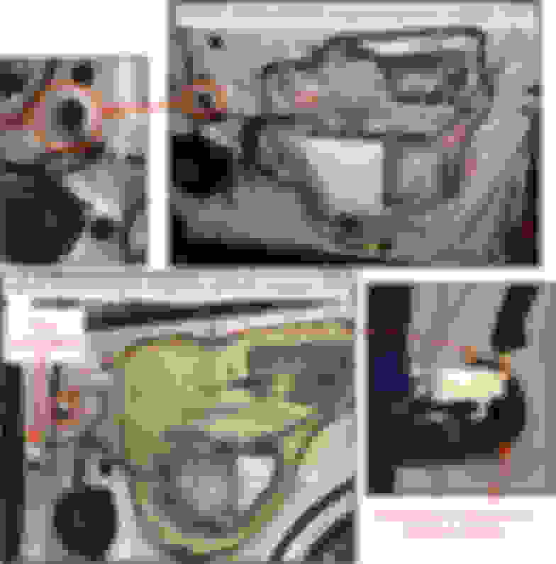
The attached images show location and colors of battery, ground, and illumination wires in the doors.
To disconnect the power window connector, push the release tab sideways, with a small screwdriver, toward the connector, and then withdraw the plug. Fuses can be temporarily pulled to remove battery power from each power window plug while adding the wire taps to battery. All power window fuses are 20A.
Door . . . . . . . . Fuse . . . . Location Front Left . . Door F/L . . . . IP** Front Right . Door F/R . . . . IP** Rear Left . . . Door R/L . . . IP** Rear Right . . Door R/R . . . FB2*** ** Fuse panel under instrument panel *** Under-hood fuse box near wiper fluid filler
To expose a wire, cut back some of the harness sheath material (replace afterward with vinyl electrical tape). I slide a craft stick ("Popsicle stick") into the harness to prevent accidental damage to a wire while cutting the sheath.
The wires I marked "battery" are what you call "continuous" 12V.
I think your kit uses the "Accessory 12V" (ACC) to unfold the mirrors. Unfortunately, I do not think there is an ACC wire available in the right front door. Depending on which connector Lexus used for your mirror control switch, there MAY be an ACC wire available in the left front door.
One option is to use the "illumination" wire as a substitute for ACC. This wire is powered only when the tail lights are turned on.
The latest Canadian daytime running lamps regulations require tail lights to be on as well, but your NX may pre-date that requirement.
It might be inconvenient to have to turn on the tail lights during the day, particularly if that action causes the instrument panel gauges to dim.
I think you're right, it uses the ACC.
I just tested one module today without connecting the ACC (because it says it's optional in the description) and it didn't work...
I will re-test tomorrow with connecting the ACC.
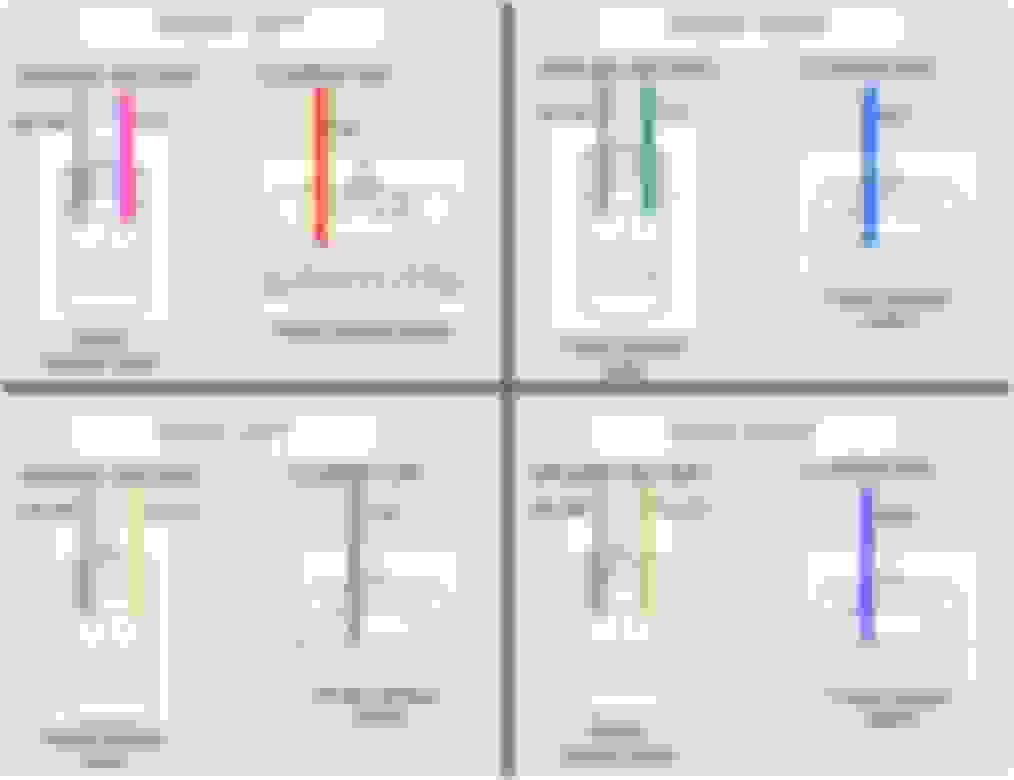
It appears you have the switch specified for vehicles with memory mirrors and seat positions. This switch does not connect to the mirrors directly. Instead, it connects to a dedicated electronic control unit that drives the mirror motors.
The various shades of green wire may not exactly match your harness, so refer to the connector terminal numbers for confirmation of function.
Yes, I forgot to specify that detail about the control unit, sorry. The vehicle has memory mirrors and seats...
I need some help with wiring some modules for automating the folding/unfolding when I lock/unlock the doors. I am fairly good with electronics but for some reason, in this case I am a little confused.
I found in this forum some threads talking about same module but it was installed on a different Lexus model which didn't have the controllers for memory/mirror switch in the door.
So, let me start. First, here is the wiring diagram for the aftermarket automation modules:
Now, here is the module itself, apparently one of these goes in each side front door:
Would someone help with connecting the terminals for this please?
Thanks in advance!
Last edited by zozoramelu; 06-23-23 at 02:36 AM.
Reason: upload photos
How I understand this wiring diagram adapted for my car (with memory seats/mirrors) is: I will have to cut the 2 wires that go from the controller module to the mirror assembly and connect the grey and white ends of this to the 2 cut wires that go to the mirror and the orange and brown ends to the cut wires that go to the controller. Am I totally wrong or not?
Last edited by zozoramelu; 06-23-23 at 02:45 AM.
Reason: grammar
 06-06-23, 05:27 AM