Please use this info at your own risk. I will try to update this post if someone else finds a faster or safer way.
- Williamb82 (see post 19 on this thread) Managed to replace both mounts without fully removing the subframe. This may be a faster option if you have small hands and want to wrestle the left mount in and out.
I replaced both of my engine mounts today using jack stands. I had already pressed in new control arm bushings a few weeks ago. This thread is more for how to replace the mounts than the control arm bushings. However I think my method of control arm bushing replacement is easier than others I've read. If you have the proper tools to remove the lower control arms from the steering knuckle my method is probably more work. For the life of me I could not separate them even after buying tooling. Bushing removal pictures under this post.
CONTROL ARM BUSHINGS: My trick was to leave the control arms still attached to the steering knuckle. I did this entire procedure myself.
1. Jack front of car (both sides or the sway bar link will bind) Remove tire.
2. Remove the 10mm and 12mm bolts securing the wheel speed sensor and brake wear indicator wire harness. Remove the connectors as well.
3. Remove the left headlight level sensor 10mm nut from the control arm
4. Take the bolts out of the inboard sides of the control arms where they slide through the subframe. You will need to Start the car and steer all the way to the left / right to clear the rear control arm bolts from the steering Tie rod.
5. To make the assembly lighter Remove the brake caliper and hang it from the shock. Also remove the brake disc. Set the brake disc on a towel so it doesn't get damaged, mine scratched easily.
6. Remove the shock bolt, sway bar fitting link, and steering Tie rod from the knuckle (invert the nut on the Tie rod threads and use a dead blow hammer, stop hammering once the tie rod is free or the castle part of the nut will be damaged)
7. Place something soft under the steering knuckle. I used a life jacket.
8. Remove the nuts from the upper control arms. Using a dead blow hammer strike the upper knuckle a few times and the joints will pop free. Do not hammer down. Simply hammer around the outside of the joints. The shock will free them. Watch your feet and hands! Once it comes free, the knuckle will fall onto the life jacket, pillow, ect
9. Now with the control arms still attached to the steering knuckle carry the whole assembly to a hydraulic press. Kinda awkward but not terribly heavy.
10. Pressing the bushings in and out was actually fun. I used a 12ton harbor freight press ( $125 or so). I also used a $50 set of bushing press spacers I bought off ebay.
I set the steering knuckle on a glass table next to my press to get the control arms in the right position to have the bushings pressed out. If you don't have a table nearby have your friend hold the steering knuckle while you operate the press.
Helpful hint. Make sure your new bushings get pushed in at the same orientation as the old ones (only the front lower forward bushing needs to be aligned). If you press the insides of the old bushings out you can use the outside of the old bushing to help install the new ones. This avoids pressing on the new rubber when installing them.
11. After pressing in all 4 new lower control arm bushings start on the 2 upper control arms.
12. Hang the brake caliper from one of the upper control arms.
12. Remove the shock assembly, Then remove the upper control arms one at a time and press in new bushings. Swap the brake caliper to the other upper control arm once it has new bushings and is mounted.
13. Reinstall both upper control arms, the shock assembly and then insert the steering knuckle into the 2 upper control arms and partially secure it with the 2 nuts.
14. Reinstall everything in the reverse order. Tighten and safety pin everything that is required except do NOT tighten the 2 inner lower control arm bolts
15. Reinstall tire
15. The last step is to jack a wheel up to where it has most of the weight of the car. Then tighten both inner lower control arm bolts. Set the wheel down then do the other side.
ENGINE MOUNTS: For safety I highly recommend using a jack stand under the engine while the subframe is removed.
Here is a little how to if anyone is interested. I had help during the 10 minutes of putting the subframe back in place. Otherwise it can be done alone if you dare.
1. Remove splash shields from the bottom of the car. 2. Disconnect rack and pinion wire harness ( 3 plugs) and tuck it up out of the way in the fwd engine compartment. 3. Mark the steering shaft on the rack and pinion side ( lowest one) . Remove the locking bolt from the steering shaft and slide the steering shaft up off of the rack and pinion. 4. Remove the tie rods from the steering knuckles. ( thread nut on upside down and whack with a dead blow hammer to loosen each side) 5. Remove the 4 rack and pinion mount bolts. Keep track of the 4 nuts. The rack is fairly heavy 60lbs or so. I lowered it onto my chest while on a creeper. I recommend getting someone to help lower it. 6. Remove 2 10mm bolts on each fwd lower control arm that secure the speed sensor wire. You don't need to disconnect any sensors. You simply need a few more inches of slack in the wire harness for the next step. 7.Also remove the 1 10mm bolt for the headlight level sensor on the rear lower control arm left wheel only. 8. Remove the sway bar 2 nuts, 4 bolts. 9. Remove the forward lower control arm bolts that go through the subframe. Remove the rear lower control arm bolts that goes through the subframe. You do not need to remove the control arms at the knuckle. They can stay attached. 10. Lower all 4 control arms out of the subframe. 11. I used ratchet straps to pull the steering knuckles away from the car. Secure them to something heavy in your garage. You only need to pull the steering knuckle and control arms a few inches outboard. This is so the control arms don't get caught up when you lower the subframe. 12. Remove each lower engine mount nut. 13. Using some 2x4's and carpet for padding jack up the oil pan slightly. I jacked mine up about 1/4" this is mainly to make sure the engine is fully supported by the jacks and not resting on the mounts. I used 2 jacks it helps stabilize the engine. Once you remove the subframe the engine can tilt causing headaches. By using 2 jacks under the oil pan the engine is stable and adjustable. 14. Remove all 4 subframe bolts and nuts at the front crash bars. 15. Remove all 4 bolts behind where the sway bar mounting points are. The big black steel brackets will stay attached to the subframe and lowered as an assembly. 16. Remove all 4 main subframe bolts to lower the subframe. This is heavier than it looks. You need to slide it rear about 2 inches to clear the fwd crash bar mounting point. Mine pretty much fell out. Getting it in is a lot harder. 17. Remove the oil dipstick 2 10mm bolts. No need to pop the hood. The bolts are easily accessible from under the car. Slide the dipstick tube up to give yourself some room. I didn't remove the dipstick tube completely, just slide it up. The dipstick tube was nearly touching the top of my right engine mount threaded mounting stud.
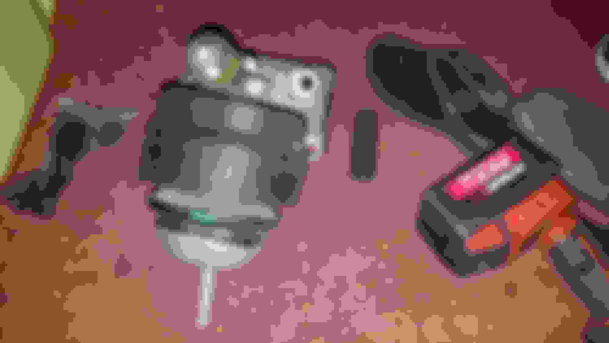
1/. 1/. 18. 2 Very IMPORTANT STEPS....1. There is a small 1/4" plastic spacer between the engine mount and the UPPER mounting bracket. New engine mounts do not come with the spacer. You need to remove it from your old mount and put it on the new mount before installing it. 2. The mounts are identical but you need to orientate them the right way. The mounts have little alignment pegs. Make sure the pegs are in the same location as you removed them. 1/. 1/.
19. I had to remove the engine mounting bracket with the engine mount on the right side as an assembly. My 17mm wrench would not fit to remove the top engine mount nut. 20. The left mount I was able to use a ratcheting 17mm wrench to remove the top mount nut. 21. Once you have the mounts and important plastic spacer swapped out you can start reassembly.
22. Subframe mounting:
Watch out for the steering shaft while you mount the subframe. I think It hangs down far enough to get jammed in the subframe if you bolt it on without looking. The subframe fitment on the front crash bar mounts is tight. You will most likely need 2 people, rubber hammer, and a small screw driver to line the holes up once they are close. This is the only step I had help with. First I bolted up the front crash bar mounts, not tight). Then I did the 4 main large bolts that hold the subframe. Once the 4 main bolts are snug the 4 bolts near the black steel sway bar area should line up. Once I had 2 bolts in on the right sway bar area I had to loosen the 4 main subframe bolts again to move the subframe just a little to line up the other 2 bolts on the right side.
Taking the subframe out as an assembly with the 2 black steel frame pieces still mounted to the back assures the subframe gets bolted very close to where it was originally. The 2 black steel frames on the back have 2 bolts each. In my case they didn't have much wiggle room. If it wasn't lined up perfectly those bolts were not going in. Next install your control arms. The control arms need to be installed before the rack and pinion. If you install the rack first you will need to loosen the rack mounting bolts to lower it enough for the rear control arm bolt's to clear.
A few more helpful hints I thought of....
Use a 17mm ratcheting wrench to remove the left top engine mount bolt nut. There may not be enough room to break the nut free with a standard 17mm wrench depending how your nut is clocked. I don't think a typical socket and ratchet will fit. The engine mount bracket on this left side looks much more difficult to remove. I would go buy a 17mm ratcheting wrench before attempting to remove it.
You may get lucky on the right top mount nut bolt if you use a flex head type ratchet I would be curious if that works. If all else fails the mount bracket is easy enough to access on that side.
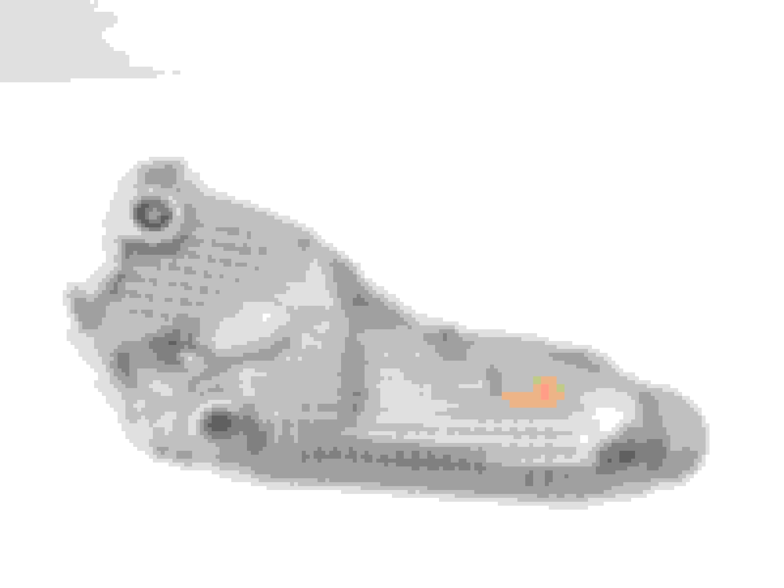
Also before you tighten the subframe make sure the alignment nubs on the engine mounts are showing through the sight holes on the subframe. I'm not sure if these could get misaligned but at this point I was tired and forgot to check. I just tightened everything up luckily they were both in the sight hole after I was done.
It took me 9 hours from start to finish to replace both mounts.
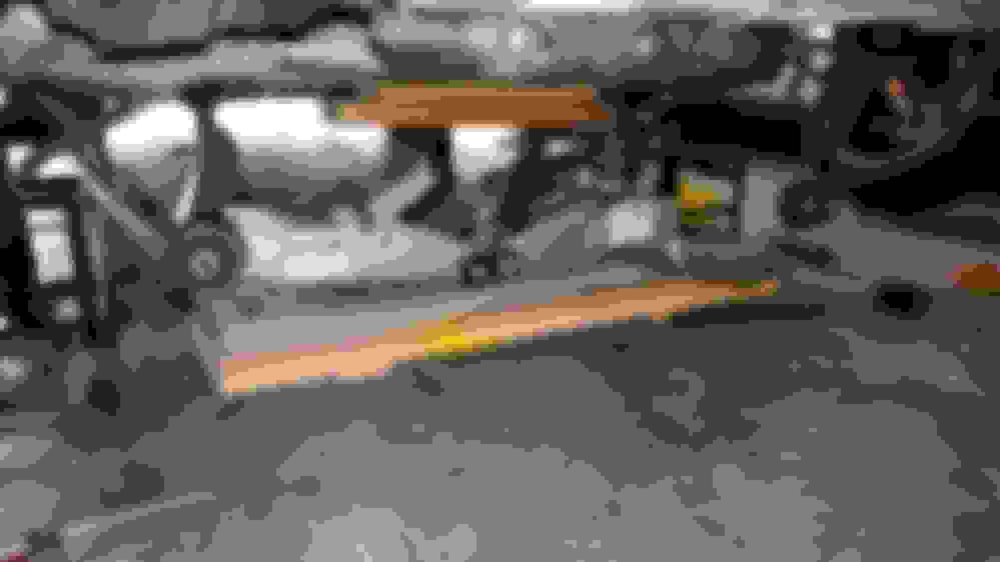
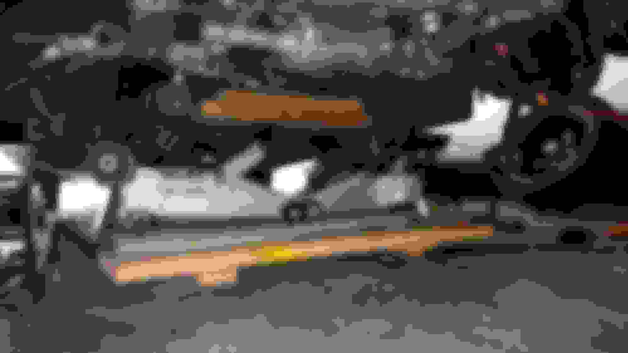
My car is now vibration free! Alignment is required after the surgery. Sub frame is out. I used a transmission jack to move the sub frame back into place for reassembly. I still needed help. I used ratchet straps to hold the steering knuckle assembly out of the way. right side I used ratchet straps to hold the steering knuckle assembly out of the way. Right side I used ratchet straps to hold the steering knuckle assembly out of the way. left side Right engine mount and bracket. Don't forget to reuse the 1/4" spacer inside of it! Another view of the right engine mount and bracket. I did not replace the small vibration damper. I did call the dealer to inquire about it. Apparently there are only 5 in stock over the entire country. I don't think it's something that normally get's worn out or needs replacing The engine is supported by 2 jacks. Use carpet and wood to distribute the load on the oil pan. You need either a transmission jack or 2 jacks like I used to support the engine so it doesn't tilt. The drive up ramps I left under the car for added safety. I supported the vehicle with 6 ton jack stands on the frame of the car. My jack stands are padded and still left slight marks in the frame. I suggest using a piece of 2x4 or similar wood between the jack stand and the frame. Toward the top of this picture the rack and pinion with it's 4 mounting bolts can be seen. This is the alignment nub I was referring to. Left side mount faces one way. Right side mount faces the opposite way. The mounts themselves are identical so you need to orientate them the correct way. There are also nubs on the top of the mounts. This is the lower threaded section that goes through the subframe. It's length is the reason the subframe needs to be out of the way. Also there are not any gaps in the cars engine area to remove the left mount . These hydraulic ramp jacks make jacking the car up a lot easier. They cost around $250 for a pair. The front bumper clears them no problem.
Use a jack and jack stand to be safe. Removing old bushing innerds Removing old bushing innerds. You will use the outside cylinder of the old bushing to press in the new bushing. Once the innerds have been pressed out you may press the outside cylinder part of the bushing out. I put a screw driver in the caliper to prevent the brake pads from moving. This is important if you accidentally push hard on the brake to start the car. I moved the rack and pinion a few times to clear the lower bolt.
Another helpful tip.
I think my engine vibrations caused a few of my heat shields to start to rattle or possibly just my milage. I noticed while the subframe was out there was easy access to all the shields. I took this opportunity to give each one a jiggle. I was able to locate 2 heat shield mounts that had much more play than the others. The bolts were tight but the shield itself had loosened around the bolt area. No rips, or holes were visible. Rather than replace the heat shield I opted to smear some rtv on the fittings. I pushed the rtv into the large ring around the attachment points. That's where the play was. After the rtv was applied I jiggled the shield around a bit in hopes to work the rtv inside the suspect joints. It has been a few days with no vibrations and no noise from my shields. It's worthy to note my engine vibrations were only while parked in traffic. The shield noise was at 10mph or so. I'd also like to add my starter noise inside the cabin was cut in half after the new mounts went in. I was very surprised by this. I can only guess my old mounts had some metal on metal contact that transferred noise to the cabin.
Ok. I love this thread!. There are some things I would do different, but this helps with my issues a LOT!!! I just got an LS460, and there is a strange rattle at lower speeds. I think this is the heat shields you mentioned. Can they be accessed without removing the sub frame? I have flex head ratchet wrenches, stubby ratchet wrenches, flex head ratchets that lock in place etc... Also, I get a vibration sometimes when stopped and in drive. Mainly only when the engine is cold, but sometimes when warm, though then it isnt as bad. Do you think the motor mount bracket bolts could be reached from the top? That way the mounts could be changed without taking the sub frame off?
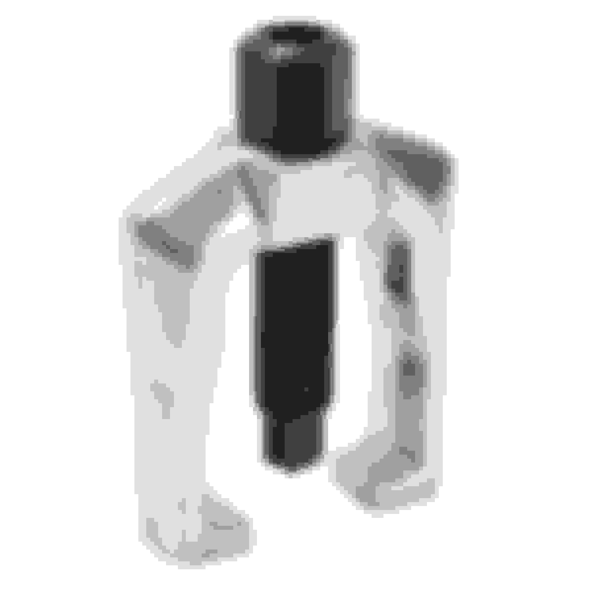
As for the control arm removal, I would not recommend hammering on the castle nut, even with it installed upside down. I would use either a tie rod, or ball joint separator, depending which one fits. Like this one
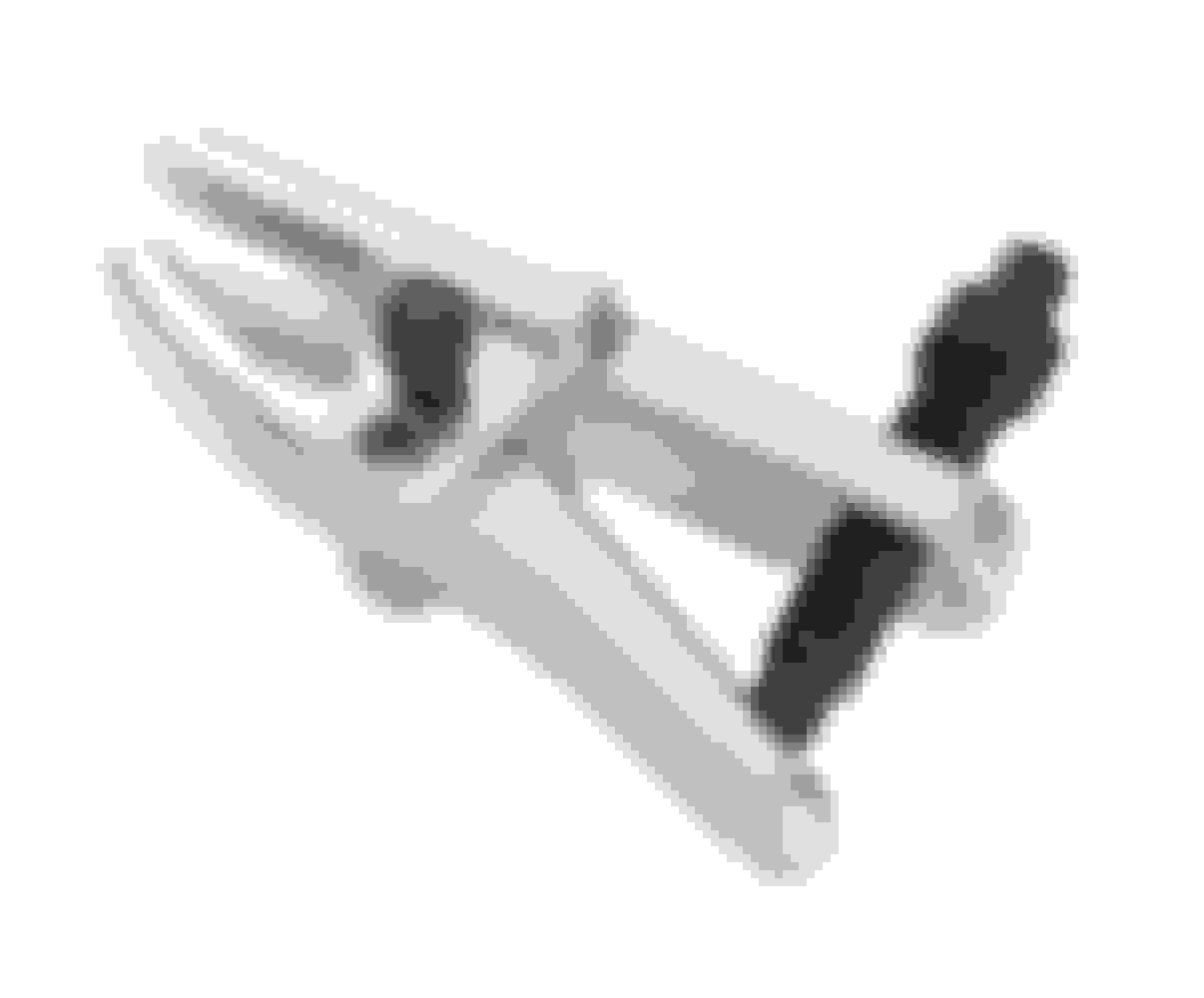
Or like this one
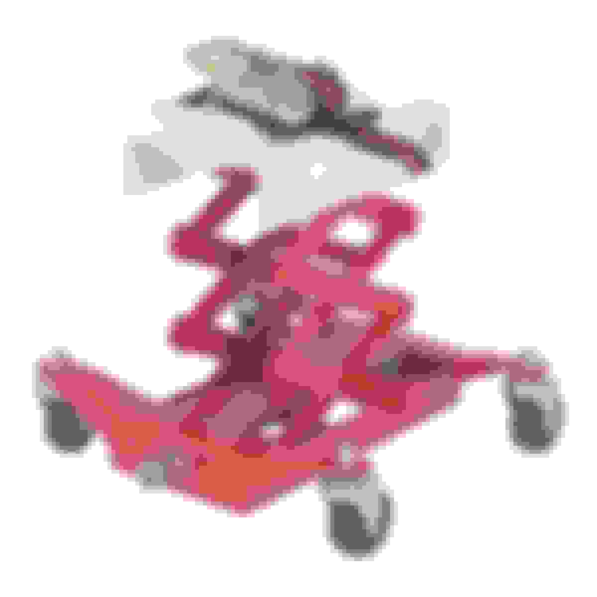
Also, instead of the 2 jacks under the oil pan, a transmission jack should work for this, so if you dont have 2 jacks already and have to buy one, you can grab one like this instead.
Yes I agree hammering on the castle nuts is not good advice. I ended up replacing one. I've had to disconnect the tie rods 4 times now. It's just a lot faster than hunting down another tool. Not any faster than my trip to the dealer for a new one though
Your vibrations while in drive but parked are most likely the engine mounts. Mine did the exact same thing. I bought the car 9 months ago during the summer, the vibration was only when the engine was cold (inside of the car would shake). Once the engine was warmed up the vibration was hardly noticeable. Last week before I changed the engine mounts the vibration had gotten so bad the fenders were rattling loudly even with the engine warmed up.
8 months ago I replaced spark plugs, resealed the valve covers and high pressure fuel pumps, cleaned the maf sensors, filters, ect. I even changed the transmission mount. Nothing helped the vibrations. Replacing the engine mounts is the cure. My transmission mount was completely shot too. I recommend changing it too.
The left mount can only be replaced by dropping the subframe or removing the engine. The mount is twice as big as the access holes on that side, it's not going to happen another way. Although it might be possible if you removed the cylinder head on that side of the car
The right mount can be replaced without dropping the subframe. Either by removing the alternator or a lower support. I believe the sway bar needs to come out too if you don't remove the alternator. I didn't put much thought into replacing just the right side.
I think you should be able to access the heat shields fairly easily. If you take the front tires tire off each has a little inner fender panel with 2 10mm bolts. It's not a large panel 6" by 6" or so. It should provide enough access. Only my right side shield was noisy. I don't think it's enough access to replace them but at least you can check them out.
Yes the transmission jack would work well for supporting the engine. I used my tranny jack to support the subframe while reinstalling it.
Ok. I love this thread!. There are some things I would do different, but this helps with my issues a LOT!!! I just got an LS460, and there is a strange rattle at lower speeds. I think this is the heat shields you mentioned. Can they be accessed without removing the sub frame? I have flex head ratchet wrenches, stubby ratchet wrenches, flex head ratchets that lock in place etc... Also, I get a vibration sometimes when stopped and in drive. Mainly only when the engine is cold, but sometimes when warm, though then it isnt as bad. Do you think the motor mount bracket bolts could be reached from the top? That way the mounts could be changed without taking the sub frame off?
As for the control arm removal, I would not recommend hammering on the castle nut, even with it installed upside down. I would use either a tie rod, or ball joint separator, depending which one fits. Like this one
Or like this one
Also, instead of the 2 jacks under the oil pan, a transmission jack should work for this, so if you dont have 2 jacks already and have to buy one, you can grab one like this instead.
I just recently replaced the lower controls and neither one of those pullers will work due to the way the knuckle is shaped. You need the bigger pitman puller to remove the rear lower arm.
I just recently replaced the lower controls and neither one of those pullers will work due to the way the knuckle is shaped. You need the bigger pitman puller to remove the rear lower arm.
Ive got both the tie rod and pitman arm puller like the first pic. I haven't bought the second tool I posted a pic of yet as I haven't needed it for anything, but it does provide more clearance on top of the ball joint stud if needed. My brother in law has a lift. I will see if I can put the LS on it and see what, if anything can be done to change that drivers side motor mount without dropping the sub frame. Ill make a tool if needed. Wont be the first time I have had to do so. If I have to drop the sub frame, well, wont be the first one. Had to drop it in my GS300 to change the rearward lower control arm bushings as the bolts drop in from the top, and the body blocks them from being removed. They changed that on the 2GS. Can't be any hard then changing the head gasket on a 95 Land Cruiser. Just did that for a friend of mine a few weeks back.
I'm thinking the driver side heat shield is the rattle I am hearing. I like that you just put silicone around the rings. I will probably use JB weld just because of the heat involved in that area. Just got to clean the crap out of it with brake clean so the JB Weld sticks to the heat shield and doesn't pop off. There is no load on it so it'll work just fine.
FYI neither control arm needs to be disconnected from the knuckles to replace the engine mounts. Only the tie rods get popped out. Hammering the inverted nut seems to be the common way on other threads. I had both tools too neither fit. If at first you don't succeed get a bigger hammer.
It is probably important to note our cars do not have adjustable camber (without buying $600 worth of different brackets). Therefor when the subframe is removed every effort should be made to line it back up in it's original position. I think keeping the 2 steel frame supports mounted to the back of the subframe helped keep things lined up on reassembly.
These pictures make my head spin. All you needed was a video of the work. Hope it makes a big difference for you after all the hard work you have done. Good Job.
A video would have tripled the time to do this job. I do wish I would have taken more pictures. I was pretty well spent after doing this in one day. Makes me miss being in my 20's, took me 3 days to get the kink out of my neck.
I had the car aligned today. After replacing both mounts the steering wheel was off about 10 degrees. I suspect when the rack and pinion is disconnected from the steering shaft the steering wheel got miss aligned. I did reconnect the rack steering shaft to the steering shaft (car side) in the exact spot it was removed. When disconnected there is a lot of play in the upper shaft that goes to the drivers wheel. I could spin it without resistance, I don't think it was turning the wheel. I suspect there is another slip joint without a bolt in that assembly, just a guess. Or possibly the rack and pinion was remounted slightly to one side. In any case the alignment fixed the off center steering wheel. The camber and caster were spot on so I guess I did a good job lining the subframe back up.
As an owner of a LS460 with a sheared front subframe mount, this will be very helpful in the coming months when I got to replace it. Thank you very much for the writeup.
A video would have tripled the time to do this job. I do wish I would have taken more pictures. I was pretty well spent after doing this in one day. Makes me miss being in my 20's, took me 3 days to get the kink out of my neck.
I had the car aligned today. After replacing both mounts the steering wheel was off about 10 degrees. I suspect when the rack and pinion is disconnected from the steering shaft the steering wheel got miss aligned. I did reconnect the rack steering shaft to the steering shaft (car side) in the exact spot it was removed. When disconnected there is a lot of play in the upper shaft that goes to the drivers wheel. I could spin it without resistance, I don't think it was turning the wheel. I suspect there is another slip joint without a bolt in that assembly, just a guess. Or possibly the rack and pinion was remounted slightly to one side. In any case the alignment fixed the off center steering wheel. The camber and caster were spot on so I guess I did a good job lining the subframe back up.
I think you may have found a solution to my oxygen sensor issue on my ls600. Dealer ,shops and manual say the engine and transmission have to be removed to replace the sensor.... I have a clear view of the front O2 sensor in your pic. I'd have to make sure the awd/600 is similar enough to gain access but definitely gives me hope it can be done w/o removing the entire Motor🤔🤔
This is for sure an easier method. I'd say a quarter of the work compared to doing something like this from the top. Round up some tools and go for it my friend.