Another LED turn signals for 3IS
 11-05-16, 05:08 PM
#1
Driver
Thread Starter

Hi all,
After reading a few attempt for LED turn signal from other members, I like the one by E46CT https://www.clublexus.com/forums/is-...oper-leds.html instead of doing exactly what he did, I did a little different.
The LED bulb choice from his threat is excellent (bright and draws decent amount of power.)
Let explain a little about power draws from those LED bulbs and why he said we only need 1 load resistor per side instead of 1 for each corner (2/side). Each of those LED draw about 0.45A. 2 bulbs/side draw about 0.9+ Amp or about 1/2 power of a filament bulb. So the total power draw from 2 LED and a load resistor is equivalent to 1 and 1/2 of the filament bulb. This total power draw is more than enough to fool the bulbs fail circuit in the flasher unit (if there is one). To use 1 resistor/side setup, the total power draw for 2 bulbs must be at least 0.9Amp. Anything lower will not work with 1 resistor setup. Also don't be fool by the (15W, 30W, 60W .... ) watts that the seller advertised. The only way to find out if it work is measure the power draw.
The plus side of this set up is if any of the bulbs or resistor fail, it will trigger the 'bulb fail' feature in the circuit and you will have hyper-flash. If you use 4 resistors set up, if any of the LED bulb fail, you will not get hyper-flash (only when one of the resistors fail).
Ok here is my setup.
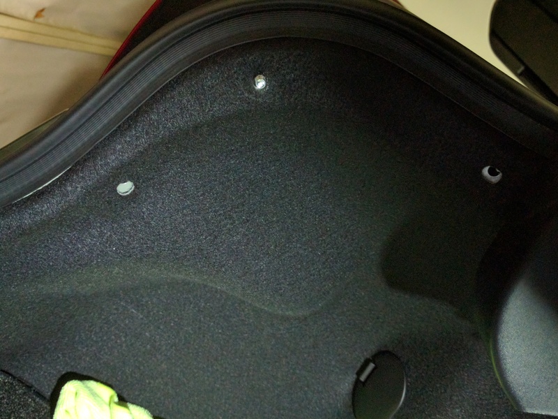
- Pop the trunk and use your famous panel removal tool and pop out these 2 clips (left and right in photo). The middle one just a screw so turn counter-clockwise to remove.
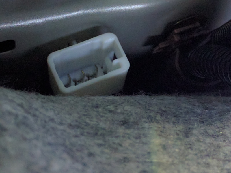
- Release this connector. This is the connector that goes to the light assembly.
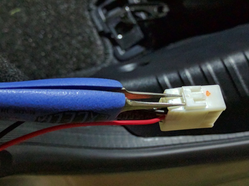
- I use this tiny tweezer to remove the turn signal and ground wires. Lift the lock tab on the side of the connector and poking round to remove the pins. It take some practice to do it. Some of you may not have this type of tweezer to do it. A small push pin also work.
- Make connection. I use quick connector to connect to the turn signal and ground wires. Solder is best, but I decide to just 'wrap' it to the pin instead. If I want to remove it down the road, it's much easier.
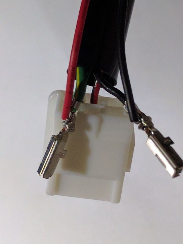
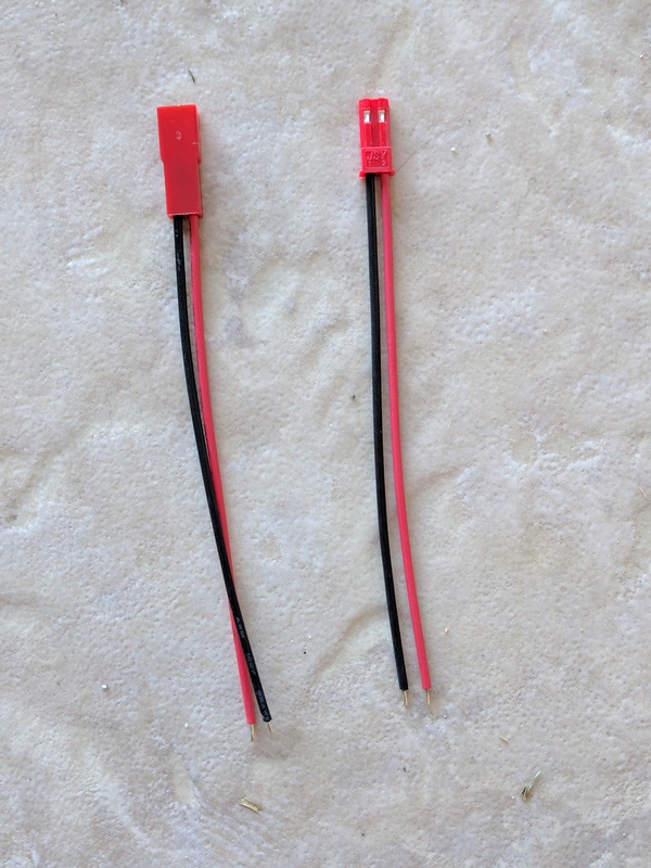
- This is the 2pins quick connector I used. It's a left over from my other project.
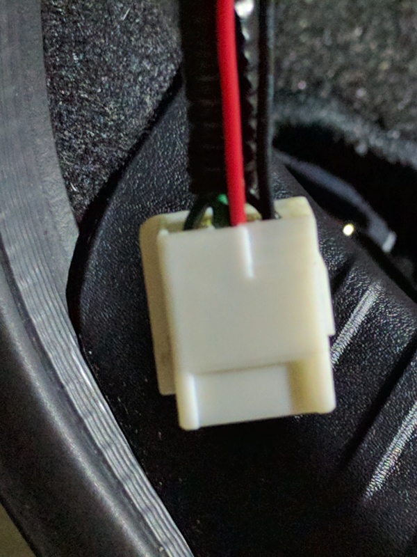
- After secure the connection, push the pin back. Also make sure to push that lock tab back. Otherwise you won't be able to reconnect back to the harness. This is what it look like after the pins is back in the connector.
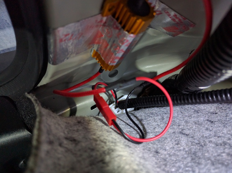
- This is where I mount the load resistor. Using some 3M aluminum duct tape to secure it.
OK all done for the back.
The front, I'm planning to do a dual brightness parking/turn signal instead of turn signal only. The 3IS F-Sport front socket has 3 wires (signal, ground and parking), but parking wire is just a dummy one. I'm going to take that parking signal from the low power wire of the DRL led.
The image below is the switchback module I built base on the part list below. Most of the parts use is what I have in hand except I have to order the MOSFET from digikey.
(1) - FQP27P06: P-Channel MOSFET or any equivalent.
(1) - 1uF25V electrolytic capacitor: acting as battery.
(1) - 1N4148 signal diode: to turn on/off the MOSFET.
(1) - 1N4007 blocking diode: prevent power from feedback.
(1) - 200Kohm 1/4W resistor: to keep the MOSFET fully off.
(1) - TO220 heat sink for the MOSFET. This thing get hot if power draw is more than 0.2A.
I'm too lazy to draw up the wiring diagram for now. Sorry, you can google P-channel as switch for how to wire it up.
Have fun modding.
After reading a few attempt for LED turn signal from other members, I like the one by E46CT https://www.clublexus.com/forums/is-...oper-leds.html instead of doing exactly what he did, I did a little different.
The LED bulb choice from his threat is excellent (bright and draws decent amount of power.)
Let explain a little about power draws from those LED bulbs and why he said we only need 1 load resistor per side instead of 1 for each corner (2/side). Each of those LED draw about 0.45A. 2 bulbs/side draw about 0.9+ Amp or about 1/2 power of a filament bulb. So the total power draw from 2 LED and a load resistor is equivalent to 1 and 1/2 of the filament bulb. This total power draw is more than enough to fool the bulbs fail circuit in the flasher unit (if there is one). To use 1 resistor/side setup, the total power draw for 2 bulbs must be at least 0.9Amp. Anything lower will not work with 1 resistor setup. Also don't be fool by the (15W, 30W, 60W .... ) watts that the seller advertised. The only way to find out if it work is measure the power draw.
The plus side of this set up is if any of the bulbs or resistor fail, it will trigger the 'bulb fail' feature in the circuit and you will have hyper-flash. If you use 4 resistors set up, if any of the LED bulb fail, you will not get hyper-flash (only when one of the resistors fail).
Ok here is my setup.
- Pop the trunk and use your famous panel removal tool and pop out these 2 clips (left and right in photo). The middle one just a screw so turn counter-clockwise to remove.

- Release this connector. This is the connector that goes to the light assembly.

- I use this tiny tweezer to remove the turn signal and ground wires. Lift the lock tab on the side of the connector and poking round to remove the pins. It take some practice to do it. Some of you may not have this type of tweezer to do it. A small push pin also work.

- Make connection. I use quick connector to connect to the turn signal and ground wires. Solder is best, but I decide to just 'wrap' it to the pin instead. If I want to remove it down the road, it's much easier.

- This is the 2pins quick connector I used. It's a left over from my other project.

- After secure the connection, push the pin back. Also make sure to push that lock tab back. Otherwise you won't be able to reconnect back to the harness. This is what it look like after the pins is back in the connector.

- This is where I mount the load resistor. Using some 3M aluminum duct tape to secure it.

OK all done for the back.
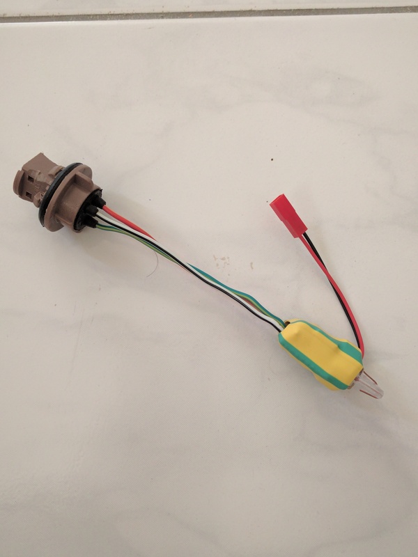
The front, I'm planning to do a dual brightness parking/turn signal instead of turn signal only. The 3IS F-Sport front socket has 3 wires (signal, ground and parking), but parking wire is just a dummy one. I'm going to take that parking signal from the low power wire of the DRL led.
The image below is the switchback module I built base on the part list below. Most of the parts use is what I have in hand except I have to order the MOSFET from digikey.
(1) - FQP27P06: P-Channel MOSFET or any equivalent.
(1) - 1uF25V electrolytic capacitor: acting as battery.
(1) - 1N4148 signal diode: to turn on/off the MOSFET.
(1) - 1N4007 blocking diode: prevent power from feedback.
(1) - 200Kohm 1/4W resistor: to keep the MOSFET fully off.
(1) - TO220 heat sink for the MOSFET. This thing get hot if power draw is more than 0.2A.
I'm too lazy to draw up the wiring diagram for now. Sorry, you can google P-channel as switch for how to wire it up.

Have fun modding.
Last edited by MatrixPC; 11-05-16 at 05:23 PM.

 04-21-17, 05:47 AM
#4
04-21-17, 03:52 PM
#5
Originally Posted by ttsport15
me? I just did the turn signals the hardest part was mounting the black relay box ...No more hideous orange bulb too ...
04-21-17, 03:56 PM
#6
04-21-17, 04:04 PM
#7
Lexus Test Driver
Join Date: Feb 2017
Location: Richmond Hill, Ontario, Canada
Posts: 6,260
Received 1,732 Likes
on
1,368 Posts
https://www.amazon.com/gp/product/B0...?ie=UTF8&psc=1
Just installed these they work great...
Just installed these they work great...
The following users liked this post:
ttsport15 (04-21-17)
Trending Topics
04-21-17, 06:17 PM
#8
correct..and no more egg yolk and a nice crisp flash worth every penny I also did the door light logo that shines on the ground..
04-21-17, 07:30 PM
#9
Lexus Champion
Or...just get this bulbhttps://store.ijdmtoy.com/No-Hyper-F...s-p/20-085.htm. No Resistor or decoder box needed. I've had experience with both, and this is even brighter.
05-15-17, 10:16 AM
#10
Or...just get this bulbhttps://store.ijdmtoy.com/No-Hyper-F...s-p/20-085.htm. No Resistor or decoder box needed. I've had experience with both, and this is even brighter.
Any one know a solution?
05-15-17, 11:09 AM
#11

I installed these all around at seemed to work at first, no hyper flash and very bright. But when I drove with the head lights on this morning apparently the current draw is different. After a few minutes both sides started to hyper flash. Changed to rear only and seems OK now. Car I have is a 2015 EU IS300h with LED headlights.
Any one know a solution?
Any one know a solution?
05-16-17, 05:00 AM
#12

Definitely let us know. I had the same issue with my RC...all 4 corners and they hyperblink, only 2 (left them in the front) and I was good to go. If adding load resistors to the back solves the problem I may have to order some. Definitely huge improvement over the factory turn signals.
05-16-17, 01:15 PM
#13
Yes and if you go to the FAQ for the item they do warn when using all 4 corners....
What resistors did you guys order? Don't want to split any wires. Guess these could be used for the fronts and are plug&play: http://store.ijdmtoy.com/Lexus-IS-LE...uide-a/692.htm
What resistors did you guys order? Don't want to split any wires. Guess these could be used for the fronts and are plug&play: http://store.ijdmtoy.com/Lexus-IS-LE...uide-a/692.htm
05-16-17, 03:40 PM
#14
Lexus Test Driver
Join Date: Feb 2017
Location: Richmond Hill, Ontario, Canada
Posts: 6,260
Received 1,732 Likes
on
1,368 Posts
Just wondering if anyone has considered using the LED bulbs that have the resistors built into the base?
It would make the process as simple as replacing a burnt out bulb. Or am I missing something?
It would make the process as simple as replacing a burnt out bulb. Or am I missing something?
05-16-17, 03:57 PM
#15
Just wondering if anyone has considered using the LED bulbs that have the resistors built into the base?
It would make the process as simple as replacing a burnt out bulb. Or am I missing something?
https://www.amazon.ca/iJDMTOY-No-Hyp.../dp/B00MJ7S1T4
It would make the process as simple as replacing a burnt out bulb. Or am I missing something?
https://www.amazon.ca/iJDMTOY-No-Hyp.../dp/B00MJ7S1T4
