How to wire your upgraded 2011+ headlights to work like stock?
 08-12-13, 03:29 PM
#1
So I've read almost every thread on this forum about upgrading to 2011+ headlights, but I still haven't found a thread or DIY on how to configure the wiring so the headlights work like a stock 2012 model. I have also yet to find a thread on how to do the Stripped headlight upgrade without taking the lenses apart.
My main questions (Which I think will help a lot of people as well), are:
1. How to transfer the ballast etc without taking apart the lens? (I've seen the one youtube video, but that video was just showing how to take the head of the cable/plug off of the wires, but not all the other steps). He had already removed the ballast from the lens, and didn't show how he got it out, or how he was going to insert it into the stripped 2012 headlight.
2. How to run the cables so that the LED strips work as the DRL's like they do on the 2011+ ISX50 models (I've seen cutting the green led cables, connecting them together and running them to a power source, but how can this be done cleanly). Can't you just somehow connect the factory DRL circuit/wire to the new LED strip wires?
3. There is also a complicated write-up on buying a circuit and wiring it up so that the LED's go to 50% once the headlights are turned on, but is there a DIY with pics for people that are NOT electrical engineering students? I wish there were just pictures showing which color wire to cut or tap into what place etc. And can this mod be done somehow with the LED DRL hack so everything works nicely together?
Now I have seen people post saying that they were able to achieve questions 2 and 3 with re-wiring, but they never mentioned how this was done. And on that note, is there anyone in the Bay Area that I can pay to configure this for me? Thanks, and appreciate any help or advice you can give.
My main questions (Which I think will help a lot of people as well), are:
1. How to transfer the ballast etc without taking apart the lens? (I've seen the one youtube video, but that video was just showing how to take the head of the cable/plug off of the wires, but not all the other steps). He had already removed the ballast from the lens, and didn't show how he got it out, or how he was going to insert it into the stripped 2012 headlight.
2. How to run the cables so that the LED strips work as the DRL's like they do on the 2011+ ISX50 models (I've seen cutting the green led cables, connecting them together and running them to a power source, but how can this be done cleanly). Can't you just somehow connect the factory DRL circuit/wire to the new LED strip wires?
3. There is also a complicated write-up on buying a circuit and wiring it up so that the LED's go to 50% once the headlights are turned on, but is there a DIY with pics for people that are NOT electrical engineering students?
I wish there were just pictures showing which color wire to cut or tap into what place etc. And can this mod be done somehow with the LED DRL hack so everything works nicely together?Now I have seen people post saying that they were able to achieve questions 2 and 3 with re-wiring, but they never mentioned how this was done. And on that note, is there anyone in the Bay Area that I can pay to configure this for me? Thanks, and appreciate any help or advice you can give.
 08-13-13, 10:51 AM
#4
I would have to agree about pictures. If someone could do the mod above and post pictures of the setup completed it would help out a lot. Just to see how the wires were ran, where was the relay located, do the wires terminate at the relay/circuit, or are you adding that relay in-line etc?
08-13-13, 11:58 AM
#5
I wanted to post a little more details on this DIY. I have done this mod myself and it works perfect.
First step will be to wire both LEDs together, both black and green. Dont cut the white one its the ground. After splicing the green(100%) wires together you will connect this wire to pin 87a.
Next after splicing the black wires (50%) together you wil connect this wire to pin 87
I'm using the Sewell headlights, so after you have cut the green wire from the LEDs the green wire that was tapped into the parking lamp will go to pin 86 of the relay. So when you turn on the parking lamps this will energize the coil switching the circuit from 87a to 87 there for opening the circuit for the 100% and closing the circuit for the 50%. From the fuse box under the hood locate IGN2, run a wire from IGN2 to pin 30 of the relay. The last wire to be connected is a ground to complete the circuit. I went from the chassis to pin 85. Be sure and remove any paint or grease to insure a good ground. Also when you purchse the relay ask for the socket that it plugs into this wiil make replacing the relay if needed a lot easier. I installed the relay in the relay box located next to the fuse box. I drilled a hole in the side towards the bottom and installed a grommet for the wires to pass through and still keep moisture out. last but not least install some plastic spiral conduit to make it lok factory. I will post some pictures to show the end result.
1. So question one is will the relay now cause the LED's to turn on and run when the car is on, since you have IGN2 running to Pin 30?
2. I'm still waiting for my headlights to arrive, so I don't have the actual harness from Sewell in front of me, but I'm assuming the green wires for the LED's (100%) are running from the headlight bulb to the plug that connects to the cars harness. So are you cutting the green wires, so now there are two dead wires that you tape up and terminate, or are you just running like a T splice into both green harness wires and connecting them together and running it back to the relay? Basically just trying to find out what happens to the terminated wires if indeed you're just cutting them so that the wires go straight from the headlights to the relay. (Same with the black 50% wires)
And where is the green wire for the parking light that you're talking about that needs to connect to pin 86? This is the whole part that is confusing without pics. Is there a separate green wires for the parking lamps, because I didn't see you mention splicing anything else besides the 100% green and 50% black wires.
3. Also it looks like you just used blade connectors, but would you recommend using something like a weatherproof plug and just running the wires to that and plugging it into the relay?
Again, I appreciate any help you can provide, and I'll definitely take a lot of pics of my install so it'll hopefully help out the people like myself that are not electrically inclined.
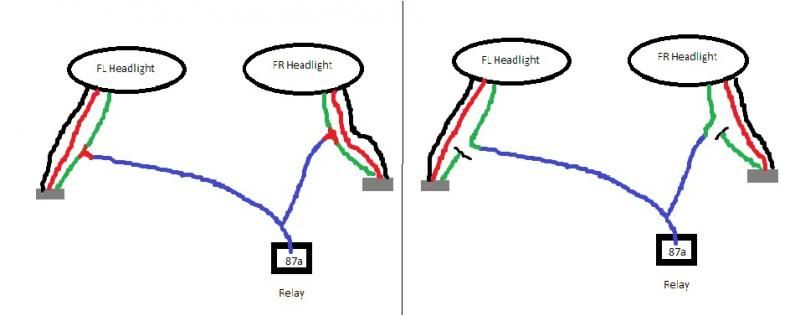
EDIT: I made a quick crappy pic to demonstrate what I meant by #2 above. Can you tell me which scenario is correct below, and I'm assuming the same would have to be done with the black 50% wires. Then I just have to figure out where the parking light wire is for pin 86?
Last edited by PumaFiveOh; 08-13-13 at 12:35 PM.
08-18-13, 08:41 PM
#6
Driver
iTrader: (8)
Join Date: May 2012
Location: Texas
Posts: 128
Likes: 0
Received 0 Likes
on
0 Posts
Sorry I didnt get back to you quicker, I've been out of town.
Question 1. Yes, the do operate as daytime running on 100% and 50% when the lights are in auto or manualy turned on.
Question 2. The figure on the right is correct. Yes you will do both green and black the same.
On the right side you will cap and terminate the wire. On the left side the the terminated wire will be the one that goes to pin 86.
Question 3. I used an enviromental splices. which have a sleeve that you heat up and makes a seal to protect from moisture and corrosion. Not sure of the availbilty of those as because they are aviation connectors. A regular blade connector would work, if you cover the splice with heat shrink.
I hope I answered everything, if not feel free to ask. I will try to help you anyway I can.
08-21-13, 02:17 AM
#7
Sorry I didnt get back to you quicker, I've been out of town.
Question 1. Yes, the do operate as daytime running on 100% and 50% when the lights are in auto or manualy turned on.
Question 2. The figure on the right is correct. Yes you will do both green and black the same.
On the right side you will cap and terminate the wire. On the left side the the terminated wire will be the one that goes to pin 86.
Question 3. I used an enviromental splices. which have a sleeve that you heat up and makes a seal to protect from moisture and corrosion. Not sure of the availbilty of those as because they are aviation connectors. A regular blade connector would work, if you cover the splice with heat shrink.
I hope I answered everything, if not feel free to ask. I will try to help you anyway I can.
Question 1. Yes, the do operate as daytime running on 100% and 50% when the lights are in auto or manualy turned on.
Question 2. The figure on the right is correct. Yes you will do both green and black the same.
On the right side you will cap and terminate the wire. On the left side the the terminated wire will be the one that goes to pin 86.
Question 3. I used an enviromental splices. which have a sleeve that you heat up and makes a seal to protect from moisture and corrosion. Not sure of the availbilty of those as because they are aviation connectors. A regular blade connector would work, if you cover the splice with heat shrink.
I hope I answered everything, if not feel free to ask. I will try to help you anyway I can.
Another quick question, does it matter which side parking lamp wire I run to pin 86? And did you just use an add-a fuse type plug for the power wire from IGN2?
EDIT - Oh and lastly, did you swap over your ballasts or did you have a loaded set? If you had the stripped set, how hard is it to swap over the ballast? Just take the cap off (Like on the Youtube video) and fish the wires through somehow?
Last edited by PumaFiveOh; 08-21-13 at 02:45 AM.
Trending Topics
08-21-13, 03:10 AM
#8
Pole Position

Join Date: Aug 2013
Location: Australia
Posts: 207
Likes: 0
Received 0 Likes
on
0 Posts
Would the relay still worked if you T-tapped it but took the green wire out of the harness (I'm scared of cutting it then not doing it properly and ending up with useless headlights)?
08-21-13, 03:26 AM
#9
As for messing anything up, you shouldn't worry. It's only a wire, and even if you somehow totally destroyed the wire, it's only a harness (that sewell sells for like $20 bucks or so). The harness connects from the headlights to the plug/harness on your car. All you have to do is cut it, use some wire strippers and connect it to your new wire that you're running to the relay.
Plus, from what 737NG said, you have to run the other end of the cut green wire to pin 86 on the relay.
08-21-13, 03:43 AM
#10
Pole Position
Join Date: Aug 2013
Location: Australia
Posts: 207
Likes: 0
Received 0 Likes
on
0 Posts
I get it, so the end of the green wire (still left in the harness) is directly providing power to the relay now instead of the parking lights.
What about the black 50% wire - what would you do with the end of that?
08-21-13, 04:00 AM
#11
 08-21-13, 04:18 AM
#12
Pole Position
Join Date: Aug 2013
Location: Australia
Posts: 207
Likes: 0
Received 0 Likes
on
0 Posts
08-21-13, 08:51 PM
#13
Driver
iTrader: (8)
Join Date: May 2012
Location: Texas
Posts: 128
Likes: 0
Received 0 Likes
on
0 Posts
Thanks bro, I appreciate you taking the time to explain. Hopefully I'll take some pics when I do the upgrade and add it to your already very informative thread on how to achieve this mod.
Another quick question, does it matter which side parking lamp wire I run to pin 86? And did you just use an add-a fuse type plug for the power wire from IGN2?
EDIT - Oh and lastly, did you swap over your ballasts or did you have a loaded set? If you had the stripped set, how hard is it to swap over the ballast? Just take the cap off (Like on the Youtube video) and fish the wires through somehow?
No it doesn't matter which side, I picked the left side
because that's what side I installed the relay on.
Yes, mine were stripped. It wasn't to hard to do the swap.
Just take your time. Removing the headlight connector was kinda
a pain in the rump. One side was easy, the other not so much!
For some reason I had two different styles of connectors.
No I didn't add an extra fuse, but that would be a good idea
Just in case.
Last edited by 737NG; 08-21-13 at 08:54 PM. Reason: Didn't answer question