DIY Hardwire Auxiliary Input to Stock 3ES Radio
 01-10-12, 08:11 PM
#1
Pole Position
Thread Starter

Join Date: Mar 2010
Location: mn
Posts: 243
Likes: 0
Received 0 Likes
on
0 Posts
I have been wanting an AUX input for my car but do not want to change to an aftermarket deck, so with the help of PureDrifters thread and some determination I was able to make one for my 2000 Es300.
Supplies Used;
4 SPDT Relays
Female RCA plugs
RCA to Aux Input female adapter and then I used a auxiliary male end that goes to a flush mount auxiliary male end that I mounted in my center console beneath the shifter, or you could use a RCA to aux male end and just run it into the glove box and just keep it simpler. That is what most people do but I feel that my method is a lot cleaner and oem-like.
Auxiliary cable preferably 1.5ft
~20ft of speaker wire
20-30 female spade terimals
10-15 butt conectors
Wire Stripers
3M Double-sided tape
Phillips Screwdriver
Flathead Screwdriver
12mm deep socket with extensions
10mm socket with extensions
15/32" Drill Bit
Drill
Soldering Iron
Solder
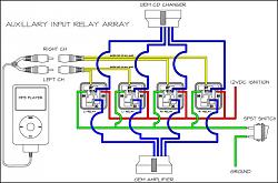
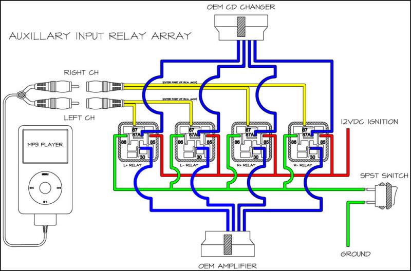
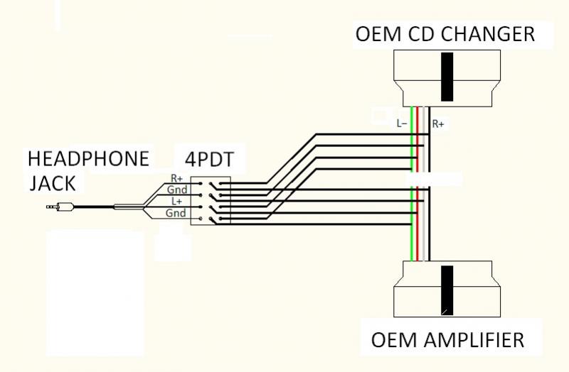
Here is a diagram taken from PureDrifers thread to show what each prong of the relays go to:
87 terimals go to + and - on the rca inputs
87a goes to CD changer side of intersected wires
30 goes to the amplifier side of intersected wires
86 goes to the grounded switch
85 goes to 12v+ power source
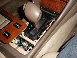
Start off by taking out your OEM radio. To do so you first use your flathead screw driver to pry up on the wood panel around the shifter. Be careful when you do this so you dont chip it! As you can see I did so at an earlier time. After you have the trim panel off, unscrew the two phillips screws found at the bottom corners of the ash tray. Pull out on the ash tray and it will pop out then uplug the wire clip.
Next you will use your flathead to pry around the edges of the AC vents to pop it out, then uplug the two wire clips.
Now you will see 2 10mm bolts on the top and 2 more on the bottom. Unbolt those using your 10mm with a long extension, pull the radio out and make sure to unplug all wire harnesses from the back of it. You should now have an empty dashboard.
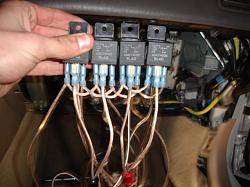
I started out by using my double-sided tape to tape all 4 relays together, then labeled them from left right being L+,L-,R+,R- respectively. Labeling them is a must.
Next I got out my soldering iron and my rca female plugs. I soldered on the wires to the rca plugs, L+ and L- went to the black RCA and R+ and R- went to the red RCA. Cut the wires to a 6 inch length and then crimp on some spade connectors to the ends. The connect the spades to the 87 terminal on each respective relay.
NOTE: The bigger prong on the RCA is the NEGATIVE one.
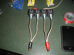
Next you will wire the 85 terimals together so that they all power up at the same time, leave enough on the last terminal to connect to your power source, I only need about 8" but that is because I spliced into my remote turn on for my amp that ran right underneath the glovebox where most of our connections will take place. That is where I got my 12v power but most of you will not have the same oppurtunity to do so and will have to find another source such as the cigarette lighter. I will explain how to remove the glovebox later. Then do the same to the 86 terminal and leave enough wire so that it will reach from behind the glovebox to wherever you decide to mount your switch. Here is what it might look like, see how they loop from relay to relay with a long wire coming off the end to make your connection with.
Thread continued on next post
Supplies Used;
4 SPDT Relays
Female RCA plugs
RCA to Aux Input female adapter and then I used a auxiliary male end that goes to a flush mount auxiliary male end that I mounted in my center console beneath the shifter, or you could use a RCA to aux male end and just run it into the glove box and just keep it simpler. That is what most people do but I feel that my method is a lot cleaner and oem-like.
Auxiliary cable preferably 1.5ft
~20ft of speaker wire
20-30 female spade terimals
10-15 butt conectors
Wire Stripers
3M Double-sided tape
Phillips Screwdriver
Flathead Screwdriver
12mm deep socket with extensions
10mm socket with extensions
15/32" Drill Bit
Drill
Soldering Iron
Solder
Here is a diagram taken from PureDrifers thread to show what each prong of the relays go to:
87 terimals go to + and - on the rca inputs
87a goes to CD changer side of intersected wires
30 goes to the amplifier side of intersected wires
86 goes to the grounded switch
85 goes to 12v+ power source
Start off by taking out your OEM radio. To do so you first use your flathead screw driver to pry up on the wood panel around the shifter. Be careful when you do this so you dont chip it! As you can see I did so at an earlier time. After you have the trim panel off, unscrew the two phillips screws found at the bottom corners of the ash tray. Pull out on the ash tray and it will pop out then uplug the wire clip.

Next you will use your flathead to pry around the edges of the AC vents to pop it out, then uplug the two wire clips.
Now you will see 2 10mm bolts on the top and 2 more on the bottom. Unbolt those using your 10mm with a long extension, pull the radio out and make sure to unplug all wire harnesses from the back of it. You should now have an empty dashboard.
I started out by using my double-sided tape to tape all 4 relays together, then labeled them from left right being L+,L-,R+,R- respectively. Labeling them is a must.
Next I got out my soldering iron and my rca female plugs. I soldered on the wires to the rca plugs, L+ and L- went to the black RCA and R+ and R- went to the red RCA. Cut the wires to a 6 inch length and then crimp on some spade connectors to the ends. The connect the spades to the 87 terminal on each respective relay.
NOTE: The bigger prong on the RCA is the NEGATIVE one.

Next you will wire the 85 terimals together so that they all power up at the same time, leave enough on the last terminal to connect to your power source, I only need about 8" but that is because I spliced into my remote turn on for my amp that ran right underneath the glovebox where most of our connections will take place. That is where I got my 12v power but most of you will not have the same oppurtunity to do so and will have to find another source such as the cigarette lighter. I will explain how to remove the glovebox later. Then do the same to the 86 terminal and leave enough wire so that it will reach from behind the glovebox to wherever you decide to mount your switch. Here is what it might look like, see how they loop from relay to relay with a long wire coming off the end to make your connection with.

Thread continued on next post
Last edited by es30000000; 01-10-12 at 08:52 PM.
 01-10-12, 08:12 PM
#2
Pole Position
Thread Starter
Join Date: Mar 2010
Location: mn
Posts: 243
Likes: 0
Received 0 Likes
on
0 Posts
So far we should have taken care of the 85, 86, and 87 terminals which leaves us with 87a and 30, the CD speaker lines.
For this we need to tap into the wire harness that plugs into the CD changer. To do so we need to gain access to it. To remove the glovebox; open it up and you will see 3 phillips screws along the top, remove them. Then look on the bottom left corner and you will see one more phillips, remove that also. Next take off the thin beige plastic piece that is on the door frame, then take off the plastic kick panel cover and pull the beige curved door trim off to reveal a 10mm black bolt. Umbolt it then pull out on the glove box, there are a few clips spread out around it so just pull in some areas, mainly among the top and it will pop out. Next there is a black trim panel that covers the CD changer, that just snaps out and disconnect the two wire plugs from it. That should leave you with your bare CD changer. There should be two 12mm nuts on the top front corners of it holding it in place. Unbolt thoses then push up and towards the engine and it should come off of it's swivel. Uplug the wiring harness and set the changer aside. Now we should have this.
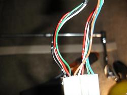
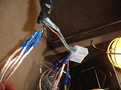
The four wires seperated from the rest are the 4 you need and these are the wires you tap into:
CDL+ Red
CDL- Green
CDR+ Black
CDR- White
Start off by stripping back the sleeve around the wires so you have more wire to work with. Then start with the CDL+ Red wire and cut it about 1.5" from the plug then strip off enough plastic to connect a butt connector to. Then connect your 87a terminal from your L- relay to the short wire you cut and stripped from the plug using a butt connector, then repeat this step for the remaining relay with their specified wires. Now the 4 short parts of the wires should be connected to the 87a pole on their respective relays via a butt connector. Now you only have the 30 pole left on the relays. Start with the L- relay and connect it to the other part of the cut wires from the CD changer put. They should connect to the long wires that head towards the stereo. Connect them to the cut wires via a butt connector and then to the 30 pole on each respective relay. It should look like this at the plug in.
You should have all 5 poles on the relays connected to the correct spots now and should be ready for a test run. Make sure your rcas and all connections are good. I forgot to mention this in the beginning but YOU MUST HAVE A WORKING CD CHANGER TO DO THIS MOD. Now take any disc in your magazine and flip it upside down. This makes it so the CD does not put out any sound at all when you select this disc to play. Put your stereo back in and turn it on, turn it to CD, select the disc you flipped upside down. Flip your switch you wired in, plug your iPod or mp3 player in, hit play and you should have crystal clear audio! Once you've verified that it works, clean up all your excess wire and tighten everything up. Chose somewhere to mount the relays, I chose to mount it to the side of the OEM amp, which is pretty much the only suitable place for it. Heres a picture to show it mounted and cleaned up.
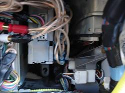
After it is mounted you can put your glove box back in the opposite of how you took it out. Then put your radio and trim panels back together and you're all done! You've now got crystal clear auxiliary input as if it came stock!
For this we need to tap into the wire harness that plugs into the CD changer. To do so we need to gain access to it. To remove the glovebox; open it up and you will see 3 phillips screws along the top, remove them. Then look on the bottom left corner and you will see one more phillips, remove that also. Next take off the thin beige plastic piece that is on the door frame, then take off the plastic kick panel cover and pull the beige curved door trim off to reveal a 10mm black bolt. Umbolt it then pull out on the glove box, there are a few clips spread out around it so just pull in some areas, mainly among the top and it will pop out. Next there is a black trim panel that covers the CD changer, that just snaps out and disconnect the two wire plugs from it. That should leave you with your bare CD changer. There should be two 12mm nuts on the top front corners of it holding it in place. Unbolt thoses then push up and towards the engine and it should come off of it's swivel. Uplug the wiring harness and set the changer aside. Now we should have this.

The four wires seperated from the rest are the 4 you need and these are the wires you tap into:
CDL+ Red
CDL- Green
CDR+ Black
CDR- White
Start off by stripping back the sleeve around the wires so you have more wire to work with. Then start with the CDL+ Red wire and cut it about 1.5" from the plug then strip off enough plastic to connect a butt connector to. Then connect your 87a terminal from your L- relay to the short wire you cut and stripped from the plug using a butt connector, then repeat this step for the remaining relay with their specified wires. Now the 4 short parts of the wires should be connected to the 87a pole on their respective relays via a butt connector. Now you only have the 30 pole left on the relays. Start with the L- relay and connect it to the other part of the cut wires from the CD changer put. They should connect to the long wires that head towards the stereo. Connect them to the cut wires via a butt connector and then to the 30 pole on each respective relay. It should look like this at the plug in.

You should have all 5 poles on the relays connected to the correct spots now and should be ready for a test run. Make sure your rcas and all connections are good. I forgot to mention this in the beginning but YOU MUST HAVE A WORKING CD CHANGER TO DO THIS MOD. Now take any disc in your magazine and flip it upside down. This makes it so the CD does not put out any sound at all when you select this disc to play. Put your stereo back in and turn it on, turn it to CD, select the disc you flipped upside down. Flip your switch you wired in, plug your iPod or mp3 player in, hit play and you should have crystal clear audio! Once you've verified that it works, clean up all your excess wire and tighten everything up. Chose somewhere to mount the relays, I chose to mount it to the side of the OEM amp, which is pretty much the only suitable place for it. Heres a picture to show it mounted and cleaned up.

After it is mounted you can put your glove box back in the opposite of how you took it out. Then put your radio and trim panels back together and you're all done! You've now got crystal clear auxiliary input as if it came stock!
Last edited by es30000000; 01-10-12 at 08:43 PM.
01-10-12, 08:12 PM
#3
Pole Position
Thread Starter
Join Date: Mar 2010
Location: mn
Posts: 243
Likes: 0
Received 0 Likes
on
0 Posts
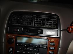
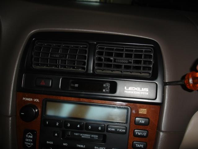
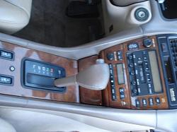
Here is how I personalized mine to give it a more oem look. This is why I need a special Male Auxiliary cable that had a flush mount female auxiliary end on the opposite end. I chose to have the flush mount auxiliary input be inbetween the seat warmer switches. I took my 15/32 drill bit and drilled a hole right at the top inbetween the two switches. Make sure to drill high enough up so that the cup holders can open all the way.
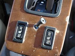
Push it all the way down tight and flush, I even added a tiny bit of super glue just to make sure it held even better.
I put my switch in the small tray to the left of the steering wheel that covers the fuse panel, it fits nicely in there and is easily hidden. When chosing your switch to use just keep it as simple as possible. Use a simple spst toggle switch, no led types, just basic. I tried to use a fancy LED one at first and it would not work, swapped it for a cheap 1.50$ switch and it worked right away!
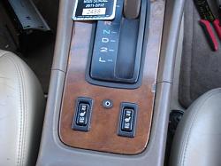
Here is a finished pic of how subtle and factory this looks
Total cost of this mod was aboout 50$ but I had to order more specific cables to get the desired result. If you wanted to keep it more basic with just a auxiliary cable coming through the center console I think you could get by spending less than 40$. This is definitely worth the cost if you have a bit of electrical know how and some patience. Total time of about 3-4 hours but if I were to do it now with the information I am providing you I would say it would take about 2 hours. Let me know if you have any questions.

Push it all the way down tight and flush, I even added a tiny bit of super glue just to make sure it held even better.

I put my switch in the small tray to the left of the steering wheel that covers the fuse panel, it fits nicely in there and is easily hidden. When chosing your switch to use just keep it as simple as possible. Use a simple spst toggle switch, no led types, just basic. I tried to use a fancy LED one at first and it would not work, swapped it for a cheap 1.50$ switch and it worked right away!
Here is a finished pic of how subtle and factory this looks

Total cost of this mod was aboout 50$ but I had to order more specific cables to get the desired result. If you wanted to keep it more basic with just a auxiliary cable coming through the center console I think you could get by spending less than 40$. This is definitely worth the cost if you have a bit of electrical know how and some patience. Total time of about 3-4 hours but if I were to do it now with the information I am providing you I would say it would take about 2 hours. Let me know if you have any questions.
Last edited by es30000000; 01-10-12 at 08:55 PM.
01-11-12, 11:17 AM
#4
i have AUX input in my 2000 ES, but the thing is whenever im using my phone (HTC) it works fine,whenever i connect my ipod to it, music is slaying on the left side only, and ive tried different cables still the same, works good for my phone, semi-good for my ipod, and ipod is brand new, like 2 -3 weeks old top
01-11-12, 11:29 AM
#5
Rookie

Join Date: Aug 2011
Location: IL
Posts: 35
Likes: 0
Received 0 Likes
on
0 Posts
i have AUX input in my 2000 ES, but the thing is whenever im using my phone (HTC) it works fine,whenever i connect my ipod to it, music is slaying on the left side only, and ive tried different cables still the same, works good for my phone, semi-good for my ipod, and ipod is brand new, like 2 -3 weeks old top
To ES30000000: There is a 4PDT (125V 6Amp) that's the size of your SPDT (do a search in Google for 4PDT) and if you use this, you can do away with your 12 Volt powered relay x 4. Don't you agree?
01-11-12, 11:39 AM
#6
Rookie
Join Date: Aug 2011
Location: IL
Posts: 35
Likes: 0
Received 0 Likes
on
0 Posts

This is the 4PDT I was referring to.
nkk M2042B2B1W01 Toggle Switch, Maintained, 4PDT, 6/3A $9 online
Contact Rating @ 125V 6 Amps - Contact Rating @ 250V 3 Amps - Contact Form 4PDT - Switch Function On/On - Number of Connections 12 - Solder Lug Terminals - Panel Mounting Type - Bat Toggle Length 11/16 In - Stem Dia 15/32 - Standards UL Recognized/ CSA

Trending Topics
01-11-12, 12:53 PM
#9
Pole Position
Thread Starter
Join Date: Mar 2010
Location: mn
Posts: 243
Likes: 0
Received 0 Likes
on
0 Posts
Sure you could use that but it may be kind of bulky and they are not very easy to find. The spdt relays are very easily available and inexpensive but that 4pdt switch should work.
 01-11-12, 01:48 PM
#12
Pole Position
Thread Starter
Join Date: Mar 2010
Location: mn
Posts: 243
Likes: 0
Received 0 Likes
on
0 Posts
That switch could be used but I personally would stick to the relays. The back of that switch would be very messy and the switch would be hard to hide, not to mention it's ugly. If you don't care about the asthetics of this mod than go for it.
And thank you, it was a bit tedious but with the info I have provided I feel like you could do it pretty quickly and painless. A sticky would be awesome as I'm sure this thread could help many people. The wires I intercepted should be the same on all 97-01 es300's with the pioneer system. Not sure about the nak system or the 92-96 es, but I can't imagine it would be too much different.
And thank you, it was a bit tedious but with the info I have provided I feel like you could do it pretty quickly and painless. A sticky would be awesome as I'm sure this thread could help many people. The wires I intercepted should be the same on all 97-01 es300's with the pioneer system. Not sure about the nak system or the 92-96 es, but I can't imagine it would be too much different.
01-11-12, 02:38 PM
#13
 01-11-12, 03:58 PM
#14
Pole Position
Thread Starter
Join Date: Mar 2010
Location: mn
Posts: 243
Likes: 0
Received 0 Likes
on
0 Posts
Purpose of the switch is to turn the relays on and off. When they are on they intrrupt the signal that the cd changer would send to the amp, hence that is how your aux works. When they are off everything functions as if your aux wasn't even there so you can listen to cd's and whatnot.