When you click on links to various merchants on this site and make a purchase, this can result in this site earning a commission. Affiliate programs and affiliations include, but are not limited to, the eBay Partner Network.
I don't recommend it, but I have lifted a GE multiple times with a one ton lift with the bumper assembly still on (you just have to be creative) so you shouldn't have a problem if you have the 2 ton which has a little more stick and obviously more capacity for the slightly more weight you are lifting. Good luck, lots of good info.
Hats off to you for documenting so much in detail - you must be looking forward to turning the key finally. Looking forward to seeing how the Soarer intercooler rebuild goes as I am curious about doing this as well. Keep up the good work!
take out your front bumper , aluminum bumper crossbar support and light support to be able to push the hoist all the way inside the bay... you will have a lot of room and that hoist is more than enough if you have a 2 ton rating hoist... engine and trans are less than 1/2 a ton.
Thanks Gerry! If that's what it takes then that's what I'll do. My best guesstimate is that the engine and trans will be 785lbs so I'll have to use the 2-ton hoist at the 1/2-ton extension setting to be safe.
Do you happen to know the torque specs Toyota wants for the aluminum crossbar and light support? I'm going to check the full SC300/400 TSRM tomorrow to see if those are even listed.
Originally Posted by RXRodger
I don't recommend it, but I have lifted a GE multiple times with a one ton lift with the bumper assembly still on (you just have to be creative) so you shouldn't have a problem if you have the 2 ton which has a little more stick and obviously more capacity for the slightly more weight you are lifting. Good luck, lots of good info.
Thank you! I did just barely get away with removing the stripped GE engine and R154 with the front bumper still on. It was very tight though and required that I jack the car down completely just to make enough room to clear the A/C condenser and the rest of the front end. I'm convinced now that barring a lift in a service bay the front bumper and crash supports have to come off temporarily when doing this in a driveway or house garage.
Hats off to you for documenting so much in detail - you must be looking forward to turning the key finally. Looking forward to seeing how the Soarer intercooler rebuild goes as I am curious about doing this as well. Keep up the good work!
Thanks atoledo! Yes, I am looking forward to that day soon for sure. I've been pushing like mad lately to get it done.
I think you're the second person with a Soarer who's expressed interest in the intercooler rebuild. The day before yesterday I was informed that my Soarer SMIC and the VVT-i shroud were being shipped back to me. I should receive them on Friday. I was told that everything went smoothly and the upper mounting bracket was re-welded spot on in its original position. I asked if they had any flow test numbers and Jonathan said they don't do that over there but he said his CFM estimates tend to be on the conservative side (and he said 400CFM might be possible with this re-core). If this SMIC does flow that well it's still not a huge number when compared to many front mount IC's but for this application it still completely beats the well respected MKIV TT SMIC's flow numbers.
(Aside, Supra owners do already have a go-to replacement OEM style SMIC for their cars. Garage Whifbitz in the UK makes one. With metal end tanks. SpeedForSale in Georgia imports those for customers and Whifbitz also sells them directly). I just found that a Soarer Z30 SMIC fits an SC300 much better since it's the chassis it was designed for.
I'm excited to get it back and test fit it. The VVT-i shroud, I was told, does fit the 91-95 Soarer SMIC but is VERY tight on there. It was recommended that I widen out the mounting holes just a bit on the plastic shroud. That should be no trouble to do. This lets us know that the early Soarer SMIC non-VVT-i shroud fits with a slight difference when compared to the VVT-i shroud. Since you have an early non-VVT-i Soarer you would not have this issue at all.
Plus, this stock (stock for a Soarer anyway) location intercooler should, along with the TT auxiliary electric radiator fan, maximize the cooling system for the times I take this car out into hot areas such as the desert. Although I won't push it by taking it to Death Valley during the hottest season ;D It gets up to 120 degrees out there part of the year.
Which reminds me... I'm on the fence about installing an IC surface water spray or other cooling system but if they can help during truly hot weather or in rush hour traffic I will. There's also a CO2 IC cooling system on the market called CryO2. I haven't read any first hand reviews anywhere to determine if that's also truly a good and proven effective option.
Adapting the K&N #57-9004 air filter kit to the USDM TT MAF:
I assembled the SupraSport MA70 Lipp Air Filter Adapter (after painting it with satin black VHT alloy wheel 220 degree paint), K&N #57-9004 filter with its included adapter, used some slightly longer 6mmx1.0 stainless steel hex head screws and some matching nuts and washers, a generic black 3" short silicon coupler hose and two HPS clamps. The other two OEM clamps are supposed to be for the OEM USDM 2JZ-GTE rubber hose that goes onto the MAF sensor but only one of them fits on the MAF side.
Note: I ended up changing the intermediate silicone 3" straight hose to one of the same diameter but with a built in 45-degree bend. A slight bit of trimming on each end and the fit was perfect an the filter was angled correctly so as not to hit or push on anything.
Once the engine is in I'll fit it in the car to see how well this worked out.
Next...
Installing the R154 transmission and clutch onto the 2JZ-GTE (out of the car):
I'm not exactly documenting the step-by-step process but I did need to look up a few sources to help me figure out how to do this right the first time. This is actually my first ever clutch job so I took a long time and followed the instructions to the letter.
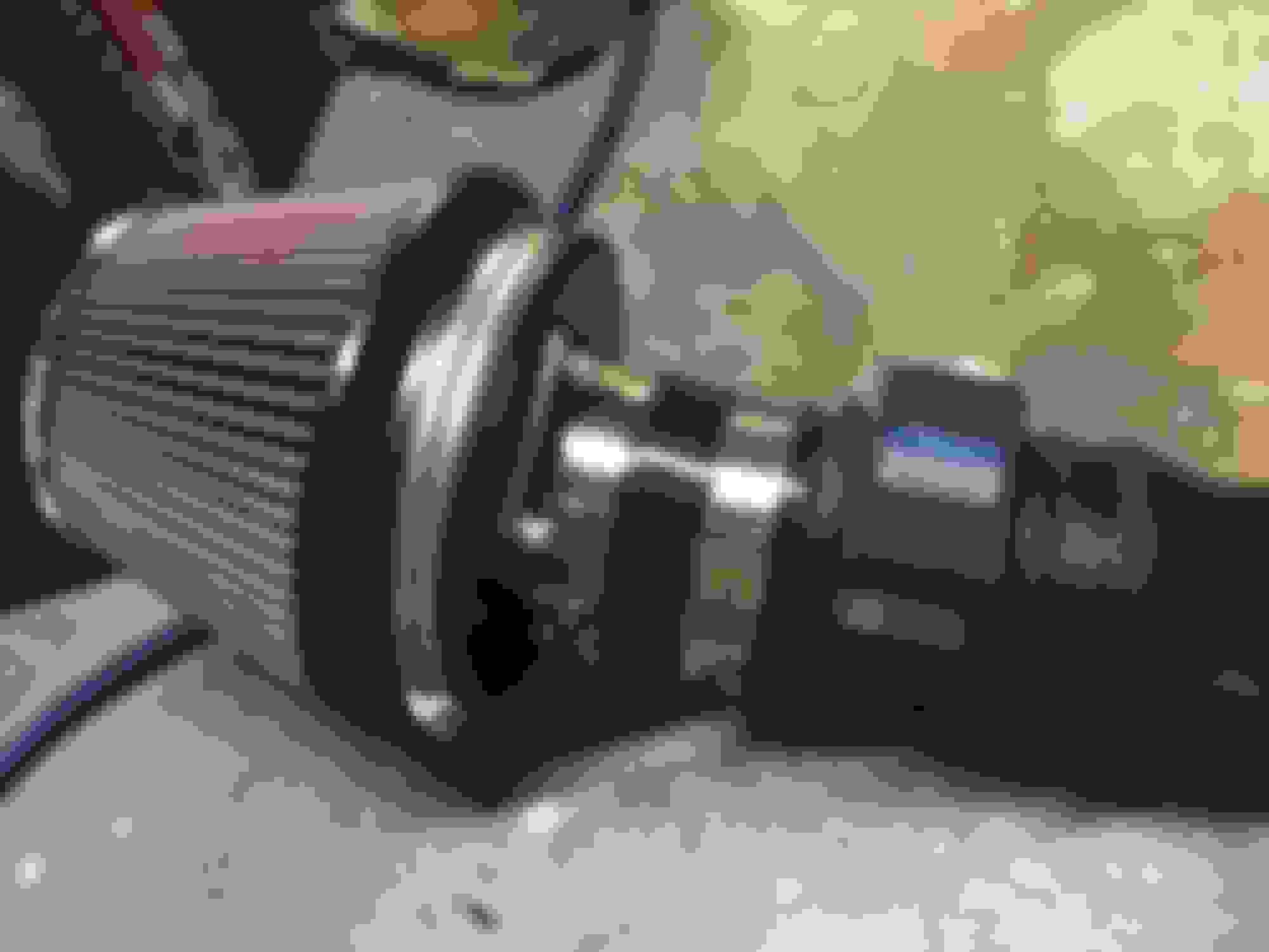
Due to time constraints I opted to remove the OEM 1JZ-R154 flyhweel I have on my 2JZ-GE engine and save it for use in a later clutch job. I didn't have time to wait for it to be resurfaced so I opened up the brand new spare flywheel I had:
This is JDM P/N 13405-46030 and no, you cannot buy it from a regular USA Toyota dealer (to my knowledge). Driftmotion, Amayama and other specialty stores will carry them or be able to import them in the USA. The three (3) dowel pins are the same as for the W58 flywheels and can be ordered in the USA: 90250-08054
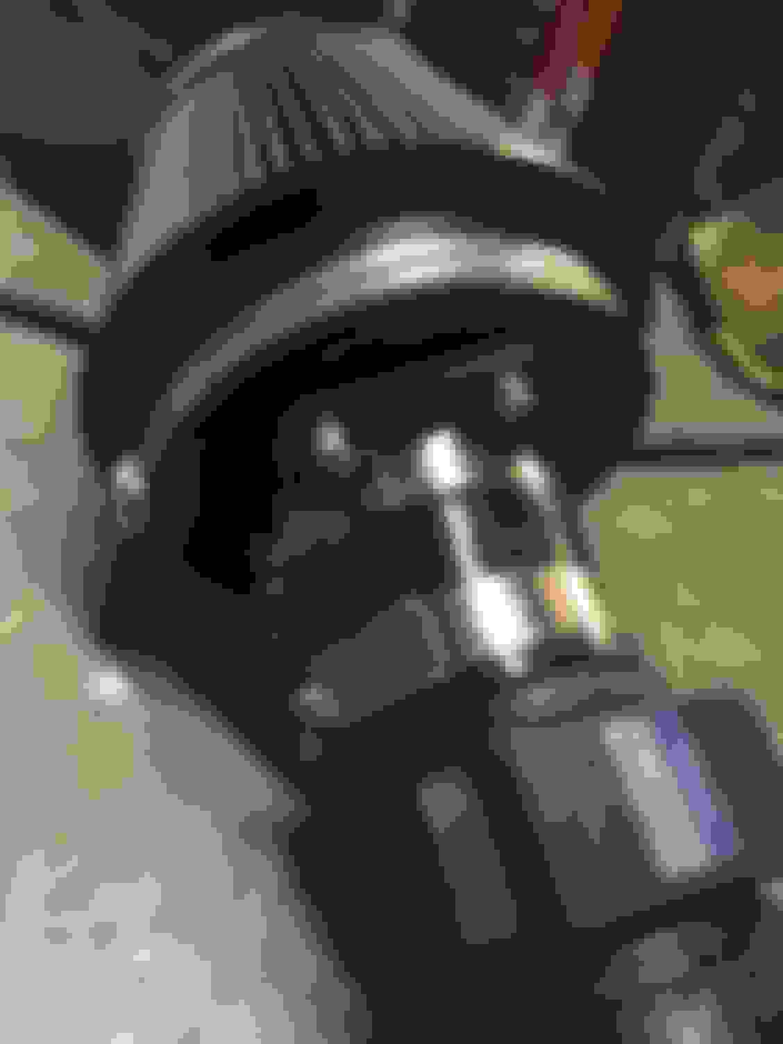
And then I had to install the dowel pins. This made me nervous but I learned a bit both from Curt Aigner's post on SF and from a post on a Mustang forum. It's not rocket science but you MUST use a BRASS hammer. Why? Because the brass is a softer metal than steel and it will give well before the steel will.
You want to tap them in as evenly as you can but once you get them in there properly they should be straight. Not pictured here, I used a digital measuring tool on the old flywheel to determine the correct depth of the dowels (since no TSRM notes on this seem to be available or I couldn't find them). I believe I measured 9.3mm or something close to that but one of them was slightly higher, perhaps to align the pressure plate into position. Basically I just copied however Speed For Sale had them set up from when they last installed flywheel dowels for me on the old flywheel back in 2013.
For the flywheel I have new ARP 1JZ/2JZ flywheel bolts. You should NEVER re-use the soft stock flywheel bolts and it isn't even recommended to re-use the ARP bolts.
As you can see below, the TSRM, Toyota has a specific pattern they want you to use to gradually torque down the flywheel bolts. You're supposed to do this in several passes, so I did three stages and gradually worked up to the required torque.
Now it should be noted that I used Loctite Red on each flywheel bolt and followed an alternative torque number of 75 ft-lbs for these. I basically started them in with a socket, then went to 25 ft-lbs, then 50 ft-lbs and finally 75 ft-lbs. Since I was using ARP's I did not follow the extra step of a final turn on the bolts as is displayed in the TSRM procedure, BUT if you are using OEM Toyota flywheel bolts you MUST follow that extra step and follow their torque requirement.
Make sure your torque wrench is in good calibration!
(Also, the trick to hold the flywheel in place with a transmission bolt and a wrench braced against one of the flywheel dowels I picked up from the Pure Function video listed below)
Here's a video demonstrating the installation procedure for the flywheel:
And another which covers the installation of the pilot bearing. I went with an OEM Toyota pilot bearing. I used the back end of a socket and my brass hammer to tap the pilot bearing in as evenly as possible. I applied a thin layer of moly grease to the mounting area on the crank before installation.
This guy also demonstrates an absolutely weird trick to remove your old pilot bearing. Just as he states it sounds like a completely half-baked idea but it seemed to work for him as you can see. My crank didn't have its pilot bearing yet so it wasn't an issue for me this time.
I wanted an OEM-like clutch for this build since I would not be pushing big horsepower. Southbend seemed to get a lot of good reviews from R154 owners so I bought a SB #16063-HD Daily kit. This uses an upgraded pressure plate with a stock Aisin clutch disc for a torque rating of 365 ft-lbs which is excellent for the stock power level. The USDM 2JZ-GTE puts out 315 ft-lbs in stock form so this gives me a good level of overlap.
If I were to do any significant modifications I'll need to upgrade it. For now, it's perfectly fine for me.
PLEASE NOTE: THIS IS THE CORRECT SIDE THAT SHOULD FACE THE ENGINE/FLYWHEEL. THE NON-RAISED SIDE.
I had previously ordered a new OEM R154 clutch spring, clip and shim kit:
Now how do you install the new shim kit and bearings? For the clutch pressure plate hub assembly, here's a very helpful tutorial. You will need a good set of snap-ring pliers. This guy makes it look very easy. It isn't but then I'm also not practiced. You can also use a screwdriver to gradually press the inner edge of the clip onto the hub while you use another (with the help of a friend) to push on the clip's other inner edge. Hard to explain in words rather than demonstrate. Of course the best way is with the best tools such as what this fellow is using in the video:
After having removed the R154 from the 2JZ-GE engine for the last time...
After cleaning the inside of the 1JZ bellhousing with a degreaser and many shop towels:
I reasoned that aligning the R154 on this $20 dolly wasn't going to cut it, even with the hydraulic engine crane. I then picked up (not pictured) a Harbor Freight transmission jack for $100. It made a world of difference and between adjustments from that and the engine crane the R154 was aligned into place perfectly.
Sorry, I didn't get any pictures of the transmission on the HF jack.
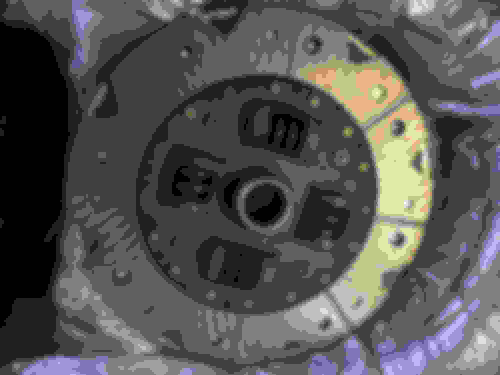
The pressure plate and clutch assembly installed inside the R154 prior to bolting it up. With this transmission you must install these on the trans input shaft first, bolt the transmission to the engine block and then you can align the pressure plate on the dowel pins and torque the bolts down in sequence.
Also, you MUST install the clutch disc the with the correct side facing the flywheel!
UPDATE/EDIT: PLEASE NOTE-- THE ORIENTATION IN THE PICTURE BELOW IS INCORRECT!! INSTALLING THE DISC IN THIS WAY IS BACKWARDS AND WILL NOT ALLOW THE TRANSMISSION TO GO INTO GEAR WITH THE ENGINE TURNED ON. I INTERPRETED THE TSRM PICTURE INCORRECTLY AND ENDED UP INSTALLING IT IN THE WAY YOU SEE BELOW. THE TRANSMISSION HAD TO BE PULLED OUT AND THE DISC HAD TO BE FLIPPED AROUND.
IF NO MARKINGS EXIST ON YOUR CLUTCH DISC TO IDENTIFY "FRONT" AND "BACK"/"REAR" THE RULE OF THUMB IS THAT THE FLAT SIDE OF THE CLUTCH DISC GOES TOWARDS THE FLYWHEEL. THE RAISED SIDE GOES TOWARDS THE GEARCASE SECTION OF THE TRANSMISSION.
LEARN FROM MY MISTAKE
I took no pictures while bolting up the transmission or the flywheel but the gist is this:
Use some Brake Clean (I can't recall how the trade name is spelled) on your flywheel to remove any smudges or oils.
The large 17mm transmission housing bolts each require 29 ft-lbs of torque while the smaller 14mm ones require 27 ft-lbs of torque. You don't need to apply final torque on all of them right away but the housing needs to be snug in its proper position mated to the block.
The pressure plate is rotated inside the bellhousing by reaching through the two inspection holes and you align the dowels on the flywheel onto the pressure plate. It may not just slide on if everything is brand new.
Have your NEW pressure plate bolts ready (here I used OEM Toyota bolts rather than ARP-- and NEVER re-use PP bolts) and some Loctite Red. Apply Loctite to the threads and start the first bolt into position with a socket wrench.
have a breaker bar with a 22mm socket ready to crank the engine over slightly (when facing the front of the engine you *only* turn it clockwise!) to align the next pressure plate bolt hole into position. Apply Loctite to the threads of that bolt and start it.
And so forth.
The TSRM says you should torque the pressure plate down evenly in several passes and the bolts require 14 ft-lbs. So you can start the torque at 5 ft-lbs, then go to 9-10 ft-lbs and finally 14 ft-lbs. You will have to keep steadily moving along with this process because the Loctite will begin to set up if you wait for too long.
Next, take your clutch fork and lube up the large pin shaft and insert it inside. Apply the C-clip with a pair of needle-nose pliers. You want the C-clip end of the big pin to be facing DOWN when the fork is re-installed inside the bellhousing. Apply moly grease to all the areas of the fork which will see surface contact.
Once that is finished, replace the inspection covers on each side of the R154 and....
While I was at it I replaced my original transmission drain and fill plugs with these allen-socket style versions which have magnets on their inner sides. It's supposed to be a recommended upgrade for the R154.
I'm still trying to find the correct torque value that these require.
Next, I noticed that after reinstalling my rebuilt starter (which I re-used from my 1993 2JZ-GE engine) it uses a different style connector than what my 2JZ-GTE harness has.
Gerrb informed me that even the JDM 2JZ-GTE's used this flat-style older starter connector for a long time.
It seems we can't replace the connector style on the starter itself but we can order the old and new style harness connectors.
Right now I don't want to buy a new starter so I am going to replace my round style connector with the older flat style. But I bought another new round style connector and replacement terminal just in case.
New type 2JZ starter connector (harness side): 90980-11400 connector & 82998-12480 terminal
Old type 2JZ starter connector (harness side): 90980-10179 connector
Update: I did end up buying and installing a new 2JZGTE USDM starter from Denso which has the newer style connector built in. It would not be worth the trouble to find and swap the new style connector into my older rebuilt starter.
Next up will be getting the this drivetrain installed
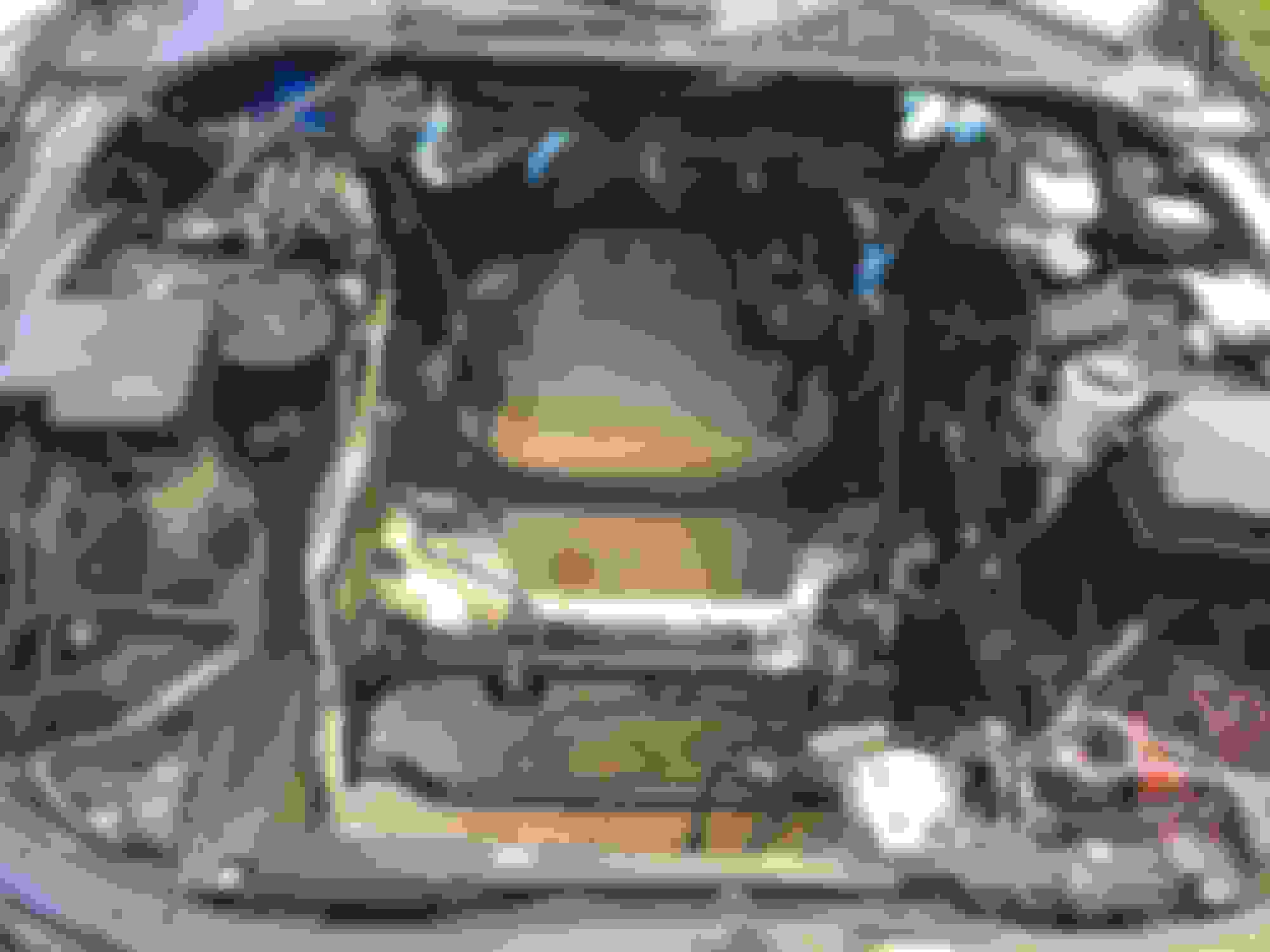
I hand cleaned the SC's engine bay in preparation. It really was amazing to see the aluminum crossmember turn from pitch black and greasy to a nice bright shade of silver.
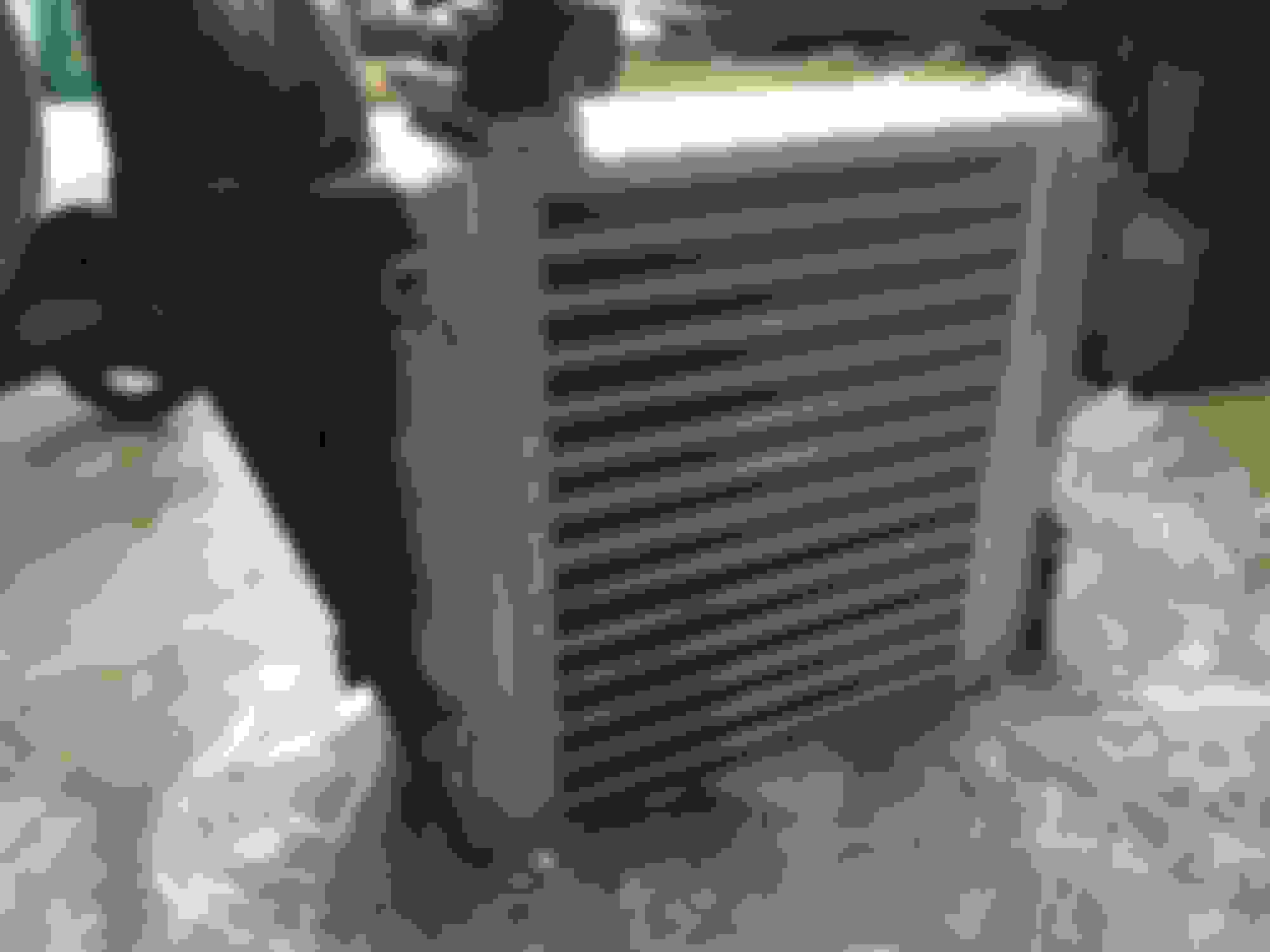
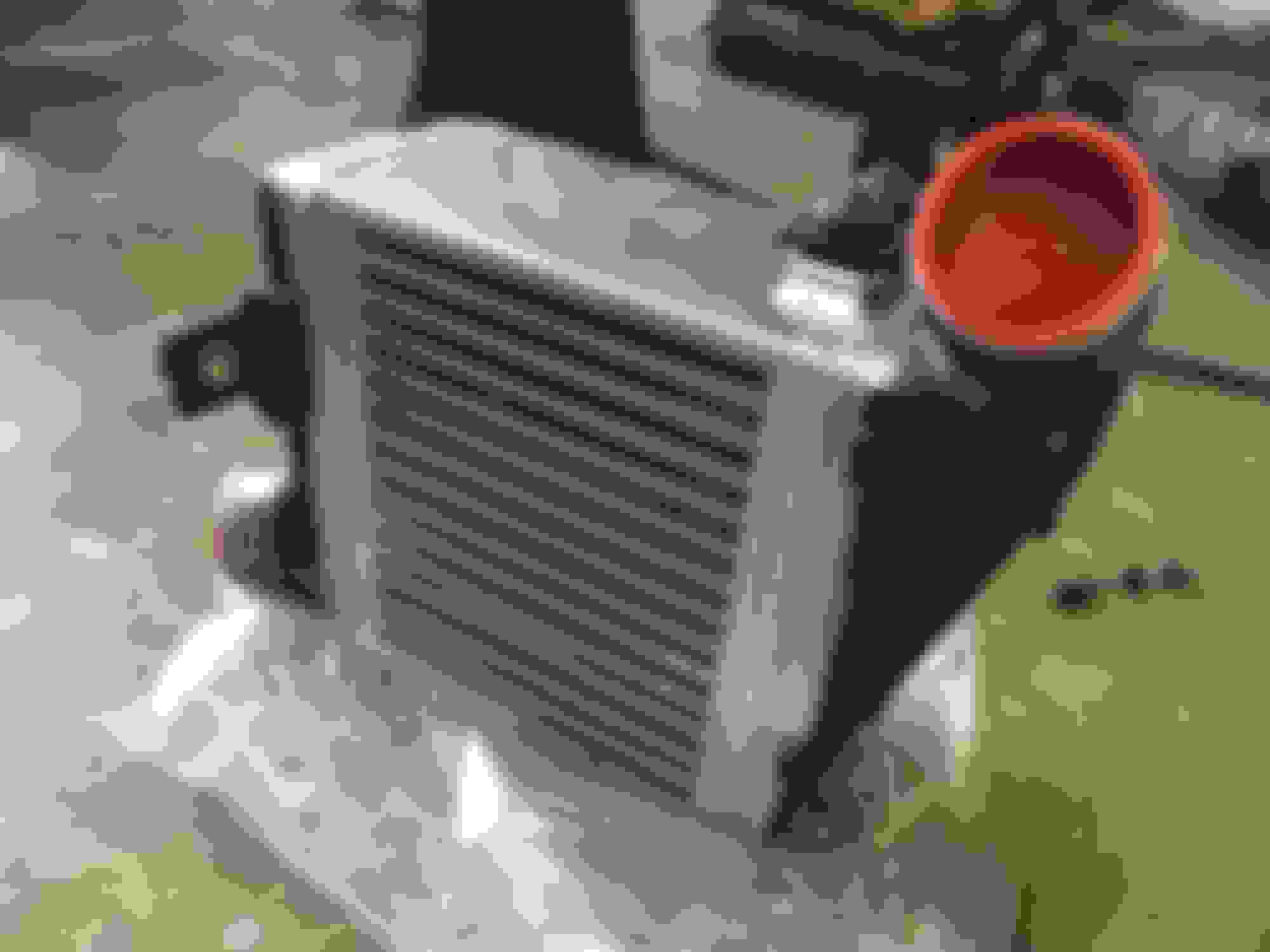
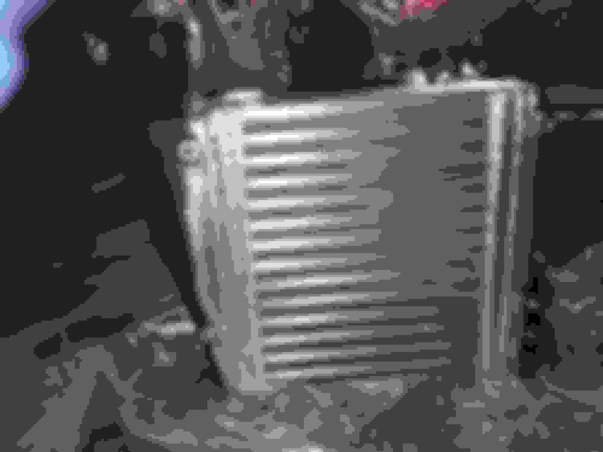
And something arrived in the mail today-- the re-cored 91-95 style Soarer side ount intercooler. I haven't had a chance to test fit it yet but it looks great! The VVT-i shroud will require some slight modification to the mounting holes to make it fit (which makes sense because it wasn't made specifically for this IC) but the dimensions are supposed to be exactly as was delivered to Bell Intercoolers. Based on what Jonathan @ Bell told me, the flow of this unit has been increased from the original 214 CFM to around 400 CFM.
It hasn't been flow tested (and I don't know where to get such a test done) but I'll take his word for it since he said his estimates as to CFM ballparks are always on the conservative side.
A teaser:
Last edited by KahnBB6; 10-12-18 at 10:40 PM.
Reason: Grammatical correction
I cleaned the engine bay a bit more. It’s not spic and span by any means but years and layers of dust and grime were removed.
Before removing the front bumper I needed to test fit the re-cored ‘91-‘95 OEM Soarer intercooler.
First, for anyone interested, here's a close look at the excellent work that Bell Intercoolers did to restore and increase the flow capacity of this thing. They made a custom welding jig to preserve the original dimensions and it is what would be re-used again for anyone who has a 1991-1995 Soarer factory intercooler who wants the same restoration done. They cut off and re-welded the original top mounting plate from the original Toyota core. The metal end tanks were re-used from the original factory assembly.
Later production Soarer VVT-i's used an IC with plastic end tanks that is similar to (but not the same as) the MKIV TT factory side mount IC. They said they could re-create/replicate one of those from scratch with the reference unit in front of them to study. What I asked them to do was simply replace the core center with a modern one and re-use the factory metal end tanks.
If anyone else is interested in this, contact Bell Intercoolers in Spring Branch, Texas and ask for Jonathan Gwinn. Full disclosure, this cost $575 before return shipping. The all-metal factory replacement SMIC that Garage Whifbitz in the UK offers for Supra MKIV TT's about the same cost for what it's worth. Using a factory style side mount, I think, is a better fit for mild power builds like mine or to restore a Soarer Z30 in its factory or BPU state of tune. Personally I'm extremely happy with the result.
But before that I had to do some modification to the ‘96-‘00 Soarer VVT-i intercooler shroud. The fit is close but not the same.
Three things were necessary:
1) Measure and cut down the upper and lower buffers to make it fit more flush on the IC surface.
2) Elongate the mounting holes on one side only.
3) Cut down the plastic reinforcement just above the mounting areas that were just elongated.
The final result:
With that taken care of I test-fit the SMIC with the modified VVT-i intercooler shroud. My SC has the late model USDM 97+ front bumper which is the same exact factory bumper that 1996-2000 Soarer VVT-i's came with.
After a little wire brush cleaning of the old Toyota mounting brackets and some trial and error aligning (there is some built in play that allows you to fine tune them before tightening down the bolts) it fit like a glove! And so did the intercooler shroud. A big thanks to the folks at Bell for being so meticulous!
Yesterday I did my solid best to get the 2JZ-GTE with R154 installed in the SC. I couldn't. Pulled it all out and stored it again on a dolly with a tire. I am tonight thoroughly worn out and demoralized. I could write a novella with the number of expletives I went through all afternoon and night.
Despite changing the pitch of the engine and transmission many times and doing very creative things to get everything into position I was still about 1-1.5" off from getting onto the motor mounts on my last try of the night. Clearly I'm not experienced at installing an engine into a car... or good at it. The engine was SO CLOSE to getting in but there was no room left and no more room to jack the transmission or any more angle with my load leveler.
Also at certain angles it was impossible to keep the GTE level to go in evenly. Again... it's very possible I'm just not good at this at all but I'd like to think I at least have the potential to be.
At first I didn't realize that the engine mounts needed to be installed onto the chassis crossmember FIRST. I did that but still couldn't get the GTE in there. Damaged my steering rack pressure sensor in the process so I'll be replacing that. I also scratched the hell out of my freshly painted lower oil pan so I'm going to repaint that now too after some masking with a big engine bag.
More than that, I was very mistaken in my prior assumption that I had a 2-ton hydraulic crane. I have a 1-ton. So at the very least I will buy myself a 2-ton crane and sell the 1-ton model.
I'm going to inspect the motor mount brackets on the new engine and compare them to the brackets from my GE engine. I might swap them onto the GTE. The intake side bracket only requires that I temporarily remove the GTE oil filter cooler and re-torque the big bolt. However getting to the bracket on the turbo side is what I dread-- that more than likely will require that I dismantle and reassemble a good portion of the twin turbo assembly all over all over again.
I am going to measure both sets of brackets well before attempting any of that.
Aside from that though I've also been thinking that I may just ring up the local independent shop of a former master Toyota mechanic and see how much it will be for him to just install the engine & trans into the car and bolt up the engine mounts and trans crossmember. All from one of his shop lifts. Nothing running, just bolting these in even if he has to drop the crossmember to do it.
I'm certain it would be very expensive just for that but I'm considering it. I can do everything else needed to get the car finished but this was a nightmare. Also, I'm concerned about breaking any little expensive things like VSVs that get in the way. I knocked a fitting off one VSV already and I'll have to see tomorrow if it was from the SC HCV assembly or one of the VSVs in front of the turbos. I unbolted both of those respective brackets but something still got caught apparently.
First, I'm going to inspect and compare the two sets of engine brackets. After that, I'm going to see who has 2-ton cranes in stock locally. Harbor Freight is the go-to and has two models for only $230 but Northern Tool has one for $240.
I'm just perplexed at how difficult it was to get this thing in there. It was not intuitive AT ALL. But again... this was my first time attempting to install an engine.
It also occurs to me that maybe it wasn't such a good idea to install the R154 and new clutch with the engine out of the car. But it all came out easily as one piece so I reasoned it must be able to go back in just as easily with the right angles. (I did remove the shifter before the old engine came out.)
I know this isn't a big deal for those experienced with doing engine swaps but I was sweating bullets. It's not an easy thing to do.
...
Tomorrow I'll start fresh and consider my options. For now, I'm going to enjoy this nice bottle of cabernet and watch some good sci-fi. I fought the car... and the car won.
Gerry, it also echoes the advice you gave me yesterday. I will try shortening the load leveler chains though. I didn't try that.
Looking at this thread... http://www.supraforums.com/forum/sho...me-Crossmember ...I'm tempted to remove the crossmember once the engine and trans are hanging in the bay but I don't think that would be a good OR safe idea.
I'll add, the engine mounts I am using are Toyota OEM for a Supra TT. They bolt right in to the SC chassis.
don't give up Craig . It was your first try so it is alright that you didn't get the mounts into those cross member holes. You will eventually get it in there. I too in my first try damaged that gray pressure sensor .
another way to help level the engine / trans while trying to shoot those mounts into the holes is jack up the tail end of the transmission aside from keeping those chains of the leveler short to have more room to play around. Once you have the bolts of those mounts sitting on the flat surface of where the cross member holes are ... just a matter of pushing and re positioning engine to get the mount bolts in.
the most daunting I would say is getting that engine / trans over and in the bay cause any mishap will render the front of the car useless but once it is in there , getting it inside the holes maybe a bit tricky but not anymore dangerous since you are not lifting it anymore that high. So I would say your hoist will still work .
I have installed at least 10 of my engines ALONE without any help and gets easier as time pass since you get to know the technique. I would even prefer to take out engine to install or remove a transmission than install the trans down there . Just easier for me removing and reinstalling that engine .
Thanks Gerry The encouragement helps... but... whatever I do next I will not get myself into the same dead end I was in last night. And anything I do myself will be with a 2-ton crane with the final extension at a 1/2 ton rating at his point. I'm not going to mess around with the 1-ton crane any longer.
Going over the crossmember was scary each time but it always went okay other than bending my new A/C condenser slightly when taking the old engine out :/ It's functionally fine but... annoying that it happened.
So you also had the experience of damaging the little gray power steering rack pressure sensor? I've already ordered a new one (P/N 89438-30020). I'll put the old one back in for now.
Now with the mounts are you suggesting I still leave them mounted to the engine rather than the chassis as the SC300 TSRM states I should? That's how I tried it before but I was never even close to getting things lined up. Then I tried it the other way around and I was much closer... but not enough. I was always slightly too far forward or too lowered down. And when I tried to give myself more room by pushing back the jacked up R154 tailshaft I always ran out of room when the back of the engine hit the firewall.
When I jacked up the R154's shift housing (remember, mine is set up with a shifter extension housing exactly as you'd find on a 1991-1993 Soarer R154) I'd also run out of clearance within the trans tunnel opening and *still* I didn't have enough clearance to get the engine back another 1-2 inches to hover over the engine mounts in the chassis... or with the mounts on the engine method I still couldn't get anywhere close to being aligned correctly over those crossmember holes.
This is my next dilemma: even with a stronger and slightly longer crane I don't think the issues I described above will go away. Also, I feel like I need some other style of 1500lb load leveler because there was no way to get the GTE level in that engine bay even after I tried to level out the R154.
I've learned that this is just not an easy process to overcome correctly. Actually I'll rank it up there as one of the hardest things I've ever done in vehicle maintenance.
I really have to think hard and visualize how to do something different if I attempt this again myself. I don't want to damage anything major. And my poor oil pan... it's physically intact but the nice new paint is all scratched up now. I do need to mask off the engine and hit it again with another layer of VHT black and let that dry.
I'll update you on what I get myself set up with later today. And I need to find out which VSV I popped an little cylinder from and if it's an expensive one (or a discontinued one) to replace.
I know how you feel Craig. I think I spent a whole weekend with my first install. Just as Gerry said, after a couple of engine swaps it gets easier and easier.
a 2 ton crane is good to have. I always leave the mounts on the engine. Tighten the bolts holding them a bit to make more room down under, but leave them a bit loose so that you can whiggle them a bit.
The angle of the motor when it�s hanging on the crane is important as well. I have marks on the chain I use so that the angle will be the same every time. I also use a transmission jack to be able to make small alterations. When I have the mounts up on the crossmember, I use a crowbar to help whiggle them down into the holes. You�ll have to make small alterations on the crane so that there�s not too much weight on the mounts.
If you put too much weight on the transmission jack you may cause a leaking transmission. Happend to me once. Started to leak in the midsection.
Hang in there! Good luck!
I know how you feel Craig. I think I spent a whole weekend with my first install. Just as Gerry said, after a couple of engine swaps it gets easier and easier.
Ok. That makes me feel a little better to know that it's something of a learning and skill developing process. I still feel very foolish though.
Though I'm still stuck with the feeling that there was little else that I could have done. At the 1/4 ton setting (without the engine being high of course) it wasn't so much that I needed more length from the crane arm but that I needed the SC's firewall to be designed further back. There was just nowhere further back to go to get those brackets to line up another 1.5-2"... and the R154 couldn't be jacked any higher in the trans tunnel.
Originally Posted by Lettut
A 2 ton crane is good to have. I always leave the mounts on the engine. Tighten the bolts holding them a bit to make more room down under, but leave them a bit loose so that you can whiggle them a bit.
Hmm. The larger capacity crane is an easy one to solve but this suggestion appeals to me. I had an easier time when the mounts and the little steel plates on top of them were left ON the engine. I got those stupid plates stuck a couple of times trying to lower the brackets onto the mounts in the chassis crossmember so I'm inclined to go back to doing it with the mounts back onto the engine again.
However the TSRM says I should do it the other way and I also had even less chance of lining them up that way.
Originally Posted by Lettut
The angle of the motor when it�s hanging on the crane is important as well. I have marks on the chain I use so that the angle will be the same every time. I also use a transmission jack to be able to make small alterations.
Yes, I learned this very quickly and it was absolutely essential to have the right angle. I used a 1500lb load leveler with a screw drive but the chains were not exactly short so maybe that needs to be changed on the next try. I changed my angle from pitching the R154 downward to leveling it out the closer I got to having the 2JZ-GTE in the near-correct mounting position in the bay. I would micro adjust that pitch as needed in an attempt to get the brackets (or mounts) lined up correctly but that's where I still failed.
I have a cheaper transmission jack (not a low profile one but not one of those upright piston types) but it wouldn't fit so I used a low profile 2.5 ton hydraulic car lift (Pittsburgh model) to jack the R154 from its mount in the rear or from the back of the main casing.
I will try marking the chains or leveler screw drive next time.
Originally Posted by Lettut
When I have the mounts up on the crossmember, I use a crowbar to help whiggle them down into the holes. You�ll have to make small alterations on the crane so that there�s not too much weight on the mounts.
Maybe that is, at the end of the day, one of the crucial secrets to getting this right. Although I am concerned I might accidentally put too much weight on loose mounts. They were always tight in place when I tried to mount the engine.
Originally Posted by Lettut
If you put too much weight on the transmission jack you may cause a leaking transmission. Happend to me once. Started to leak in the midsection.
Now that would certainly suck. And I already have a slight leak from the midsection of my R154 despite it having been rebuilt and resealed once and opened to Loctite a single both on the reverse shifter fork and re-sealed a second time. I wonder if some technician I took the car to might have lifted it wrong at some point after I had it rebuilt :/
I cleaned up the R154 for the new clutch job but it's crossed my mind to have SpeedForSale pull it yet again to re-seal it a third time if the issue persists. And at the same time I'd upgrade to the billet 5th & Reverse shift fork that wasn't yet available when I had it rebuilt with the rest of the Marlin Crawler and DM upgrade parts.
Originally Posted by Lettut
Hang in there! Good luck!
This angle works for me:
Thank you Anders! I'm going to decide today what I will do but whatever it is I will not do it exactly the same way again. I've got it in me to try this one more time but after that... if I fail yet again... I'm going to hand this physical installation over to a professional and flatbed the car back to the house to finish it.
I'd better get to repainting my oil pan soon today to give it time to dry.
Craig, it�s been over 3 weeks! What�s going on??? Is this thing running yet? 😉
Jim
Hey Jim! How are things going with you?
Rest assurred that work to the SC has been ongoing over this last three weeks since I last posted (wow... has it been that long already? I�ve lost track of time since then).
There is a LOT to update the thread on but briefly I did finally get the engine with R154 installed.
Gerry helped me tremendously to figure out the seating problem: I had the wrong side brackets on the engine. I ended up swapping on my GE brackets but the one on the turbo side required grinding out a little non-structural cast protrusion that was hitting my oil drain pipe.
Since that time I�ve been in overdrive. There have been many curve ***** to solve but I�m through them now I think. I�m trying to be done with the car well before July 4th. Fingers crossed. It�s often difficult to have time to be able to work on it until 9pm some days.
Everything is done now, fluids all in the engine and transmission. Exhaust system bolted up. All sensors connected. Custom wiring harness for the auxiliary fan system, oil pressure sensor, an additional sensor wire and remade foglights switch wiring now done (Weatherpak connectors ftw). A/C Mag Clutch trigger wire to make the aux fan run when the A/C turns on has been finished.
I�m down to getting the new stereo head unit wired up (the Beat-Sonic SC/Soarer adapter with brackets is a godsend) and other little wires that want +12V Switched.
And there�s one more all-important thing before I can turn the ignition for the first time:
Install the Denso TT fuel pump and wire it for either the TT Fuel ECU (I have two spare ECU�s and the connector and repair wires for it) or figure out how to do the 12V Mod with a safety relay for fuel pump automatic shutoff if the engine stops for any reason. I also have a new TT Denso fuel pump of course.
I have been so busy solving other needed things and wiring chores that I haven�t given any time to read up on how to do that fuel pump job. I�ve replaced the GE pump once with a stock one so I do know how to install the pump itself (crimp butt connectors only when around gasoline� NO soldering) but I have to study how to do the wiring for the 19-20 Amp power draw that it needs.
To complicate matters, my GE engine started sputtering before I could get my fuel tank down to 1/4 to remove the old (practically new though) GE fuel pump so I have to drain at least 10gal of fuel into cans with a siphon pump.
I bought a pump that clearly states it is rated for use with gasoline. Here�s hoping that proves to be true� I don�t want the tube breaking down chemically and contaminating the remaining fuel in the tank.
But I also haven�t been able to find out if early SC�s have any anti-siphoning devices in their filler tubes. If they do I may have to find a BIG plastic bin rated for petroleum and drain the tank from below� not fun.
Anyway, that�s where I�m at for now. So close it�s painful to not be able to start her up. But I need that wiring finished and I need that TT Pump first.
I am going to do a quick follow-up with the local race/off road engine shop owner who built my factory-stock and blueprinted short block to confirm his recommended break in procedure but it should be like this:
Comp Cams 10W-30 mineral break-in oil (in engine now). Filled 6.9quarts into a fully dry engine with stock twin turbos as per the TSRM.
600 miles stop and go city driving only. No highway or sustained speeds. 4,000RPM max for that duration.
After the first 100 of those miles I change out to another batch of 10W-30 Comp Cams break-in mineral oil.
My South Bend Clutch requires 750 miles of stop and go city driving for break-in before any hard use. Full-face organic factory style clutch rated 365ft-lbs.
After that I should be okay..?
I currently still have the 4.27 ring and pinion installed in the Supra TT Auto Torsen LSD rear end. I�ve talked to Jared at SpeedForSale about having his shop rebuild the rear end all over again with the 3.76:1 gearing but I won�t do that right away.
I am am so excited for you! This has been quite the undertaking and I have been following for YEARS now. I cannot wait to see it completed and you post a picture of an ear to ear smile! What an accomplishment Craig!! All the hard work, research, late nights, and overall dedication is finally going to pay off! Good for you my man!
I am am so excited for you! This has been quite the undertaking and I have been following for YEARS now. I cannot wait to see it completed and you post a picture of an ear to ear smile! What an accomplishment Craig!! All the hard work, research, late nights, and overall dedication is finally going to pay off! Good for you my man!
Thank you Jim!!! I wish it hadn't taken this many years to complete but it's all I could swing or as fast a pace as I could muster. All good in the end though
You forgot to add stubbornness to that list, haha. There will be pictures and I'm already smiling.
I got the dash electronics mostly wired as of last night. Still have to test the stereo and LXCC controller but it's all in there. Seriously, even if the Beat-Sonic stereo adapter is pricey I do not regret buying it one bit. The frame required some work (I'll explain that later) but the wiring was a cinch after I bought a bag of the correct size "bullet" style crimp connectors Beat-Sonic recommended to me.
I just need to make a little harness for the AutoExtrude ashtray twin gauge bezel (the same one you have) and now get to the TT fuel pump job... which I've now been reading up on. I still haven't decided yet if I will attempt to fully wire up the Supra TT Fuel ECU or just do the +12V Mod with a 20A relay (the Supra TT Denso fuel pump is said to pull 19A at 12V).
And tomorrow I get the restored driver's side tail light back from Daniel at Orangized Garage Status so I'll finally replace the leaky original LH tail assembly and cure that issue
There are still some cosmetic things to restore over the long term but I'm really happy to finally be at this stage.
 05-28-18, 08:12 AM


 .
.