When you click on links to various merchants on this site and make a purchase, this can result in this site earning a commission. Affiliate programs and affiliations include, but are not limited to, the eBay Partner Network.
Ok now I am following you. Lol. Wouldnt it have been easier and cheaper to just buy a complete engine.
Cheaper, yes absolutely. It would have been much cheaper to start with a mostly complete JDM 2JZGTE. Easier... that's a subjective question. By the time I started this swap in 2013 complete USDM 2JZGTE engines in nearly 100% stock condition were few and far between. But even then I had nowhere to put an entire engine in 2013 and also tracking down critical components that would allow me to keep this as a California BAR legal swap seemed more important to do first.
The more parts I randomly found the more I had intended to just convert over my original 2JZ-GE engine... but eventually I learned that even the GE block was not ideal if I wanted to run USDM or JDM OEM spec twin sequential turbos (it could have been done with a GE but with more work and oil lines. The oil plumbing for the twins is built into GTE blocks and this keeps things ever more close to factory spec for my purposes). And then there is the 245k miles I have on it and whatever the coolant leak currently is. My SC300 is also my daily driver which made getting a second engine to build a given necessity.
Yes, I could have started with a used JDM Aristo engine and worked from there. If circumstances had been different a few years ago I might have done this from the start. However I had to find so many USDM GTE specific parts anyway that a lot of teardown and work on a full JDM engine would have been needed anyway.
This is not the most cost effective or efficient way to do a 2JZGTE swap. It's just the most sure way I knew how to do a 100% stock USDM 2JZGTE swap such that I can make myself happy and get it registered and smogged in California legally.
Also, given all the work involved and my wish to recondition parts and use new hoses and sensors when possible I just decided that a full engine rebuild was the best thing for me. I am not building a race fuel short distance car. I intend to drive this engine a lot in many places and put plenty of miles on it over time
If I had more space to work with to begin with (and not all the way across the country) and if I did not have to factor in emissions compliance I could have probably built a 600-700hp race fuel 2JZ for what I've spent on this engine to date but then the intended use of the SC300 would have been very different.
For how I intend to use this car over time, a mostly "new" engine that is closer to stock or BPU power is well worth the investment to me. I've wanted a uniquely set up car like this since I was sixteen.
Suffice it to say I will only be building a rare, completely factory spec and emissions legal engine like this once. Once in this way is enough
Sorry it's taken so long to update, all. There has been a lot of personal stuff happening during this time. Documenting my slow progress on the build has been ongoing.
2JZ Cylinder Head Dowel Pins & GTE Head Gasket
Where we last left off the oil pan and lower and lower rotating assembly, plus the oil pump, water pump and oil filter housing with cooler were installed. Then the engine had been turned 180 degrees to sit upright.
After some waiting on parts and a tool or two it was time to get the head installed. This made me more than a little nervous but after studying the TSRM, ARP's own instructions, a couple of videos and some generous advice back and forth with Gerrb (as always, you're amazing, my friend!) I got over my concerns about getting it all right and just followed the system.
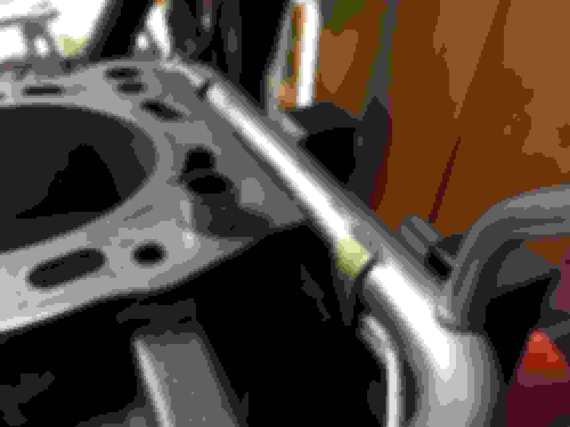
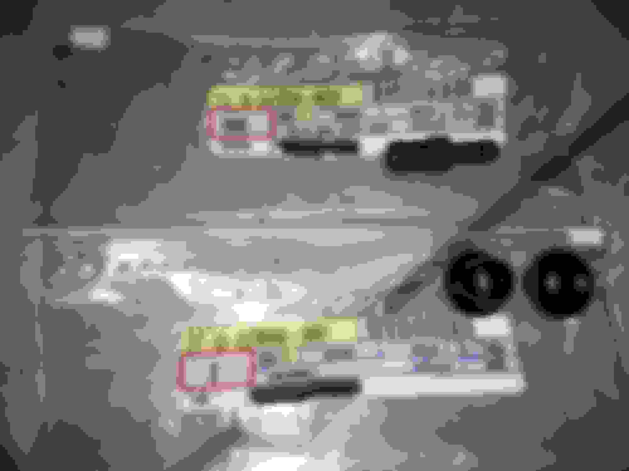
First thing was to install the cylinder block dowel pins since these were missing from mine.
FYI, for any 2JZ block these head dowel pins will be: 90253-14003. There are only two and they go into two specific locations on the deck of the block. They are installed with a block of wood and a rubber mallet, and gentle tapping to make sure they go in evenly. Using a measuring ruler, you want approximately one 1/4" to be exposed from the deck. Best to go slowly by tapping a little and then measuring... tapping a little and measuring until the height is to spec.
(GTE Cylinder Head Gasket)
Now this is very simple and a no brainer for anyone who has built one or several 2JZ's but since I've read it's kind of sort of possible to put it on upside down so I looked over what vigman was investigating in his thread:
It really is made to be foolproof by Toyota but the key as I learned is to make sure the little "serial" label faces upward to the sky at the rear of the engine near cylinder #6 and then just check to be absolutely sure there are no ports blocked and that there is no extra material where it shouldn't be not opening up a port on the block. There is some excess material around the head gasket but that's not what we're focusing on here.
It will look like this when installed correctly. This is where the dowel pins are necessary to make 100% sure the ports and cylinder walls are all aligned correctly to the gasket. Also, they make locating the head a cinch since head studs (or stock head bolts if you happen to use those) are going to allow for some alignment play. The dowels are a foolproof locating measure.
There is also a very good explanation here of why cylinder head locating dowels are so important to an accurate aligning of the various ports and cylinder bores to a cylinder head gasket and cylinder head:
intake and Exhaust Camshaft Removal from GTE Cylinder Head
In my case when I had my TT head rebuilt I also had the stock TT cams inspected and fit to shim the valves. Since this was all done by Driftmotion in California and the engine was going to be built in Florida I had them leave the cams installed for shipping purposes. They wrapped the head up very well and double boxed it with plenty of foam padding.
This meant I had to remove the cams first before I could fit the head onto the engine block and fit the head studs.
Just the same as installing them, there is a specific order that is followed to take them out. This is covered in the Supra MKIV TSRM Section EG-46 "ENGINE MECHANICAL"
The order shown is very similar to the one for the cam installation. The instructions say "several passes" and boy did I do a lot. I just kept the same amount of turn distance for each numbered bolt until, finally, they came out. At a certain point some cam bolts will feel completely loose while others will feel like they've still got plenty of tension. I do not recommend thinking the order can be skipped at this point-- keep following the TSRM order until the last few tensioned bolts come loose on their own along with the cam itself. I believe this requires a 10mm socket. A ratchet wrench or a small breaker bar can be used. Just keep each turn the same for each bolt. I did 180 degrees for each of mine.
12 bolts for each cam, not including the two caps at the very front which are removed first on their own.
You will find that each cam cap bolt will be torqued down at exactly 14 ft-lbs.
Note: there is an order for the intake cam and an order for the exhaust cam. Similar but slightly different according to the manual.
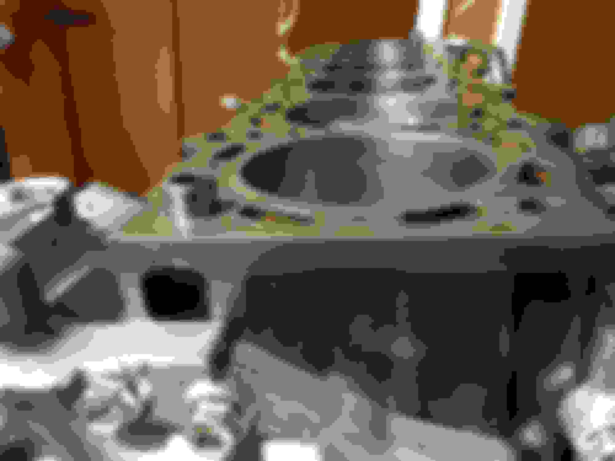
I found two identical height blocks of wood (not pictured) about 1.5" in thickness and set them just at the edges of the length the cylinder head would take up. I then set the edges of the cylinder head short of the #6 and #1 combustion chamber valves onto the blocks so as to keep the valves that were compressed below the head's lower surface from bearing a good portion of the weight of the head and cams (some 75lbs or so?).
I used the flat sides of old cardboard box shipping boxes as a working surface on my table. This will come in handy later when things get greasy.
Since I love visual aids I labeled each bolt location with painters tape. I did this for the intake cam and then all over again for the exhaust cam.
Also, you want to keep all your cam caps (and bolts because why not?) organized in the order they were removed. If anything does get mixed up, Toyota does label exactly which cap goes where. On the top of each there is an "E" for "Exhaust" and an "I" for "Intake" and after that a number telling it's spot in the order of whichever side it is supposed to go on. The order does matter but it is extremely simple.
For those who don't know, cam caps are machined for the head they come with and NEED to stay with that cylinder head.
Addendum:
This is a good explanation of the basic principles involved with handling a cylinder head that has camshafts still installed and how to remove them properly. Things like not setting the weight of the head on valves that are compressed and protruding below the mating surface, not setting onto cams, how to remove cam gears, etc.
Please note that this video uses a Mitsubishi 4G63 four cylinder twin cam head and some specifics will not apply to Toyota JZ inline-six cylinder heads. The maker of this video is very thorough, however and many of the principles are universal so I thought this would be a good primer to include. Remember to follow the Toyota Supra or SC300 Engine TSRM for all specifics such as torque values and the required cam cap removal (or installation) sequence for our JZ engines.
The GTE head was lowered onto the head gasket and dowel pins with some help. It went right on and aligned perfectly.
Then I began to install the ARP head studs.
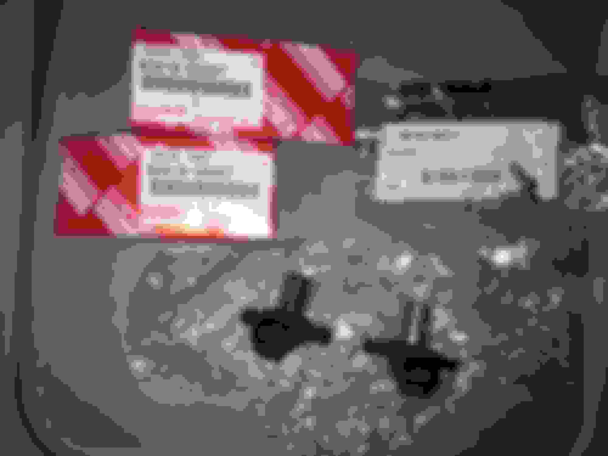
Here is the instruction sheet that comes with 2JZ spec ARP head studs:
And here is the packet of ARP's torque fastener assembly lubricant:
And the studs themselves, partly stacked on top of themselves. There are fourteen in total:
And... some Toyota OEM 2JZ head washers. These are the correct outer diameter and absolute flatness required for something as critical as head stud washers. When you compare the supplied ARP washers the outer diameter is *ever* so slightly different and the thickness is extremely close to the OEM washers but... off by a very, very minute margin. The biggest concern of mine is that the ARP washers were not perfectly flat and this would introduce an irregularity into the process. I have read in the past of the ARP washers "digging" into the aluminum of the head somehow or causing an issue of some sort.
With all of that to consider, just order a set (x14) of OEM 2JZ head washers P/N 90201-11034
Next, I had to grab a socket that would accommodate the extremely narrow walls around all but four of the fourteen head bolts. I searched around through a lot of threads before I finally found my answer:
A 1/2-Inch 12-point thin-wall deep socket. I at first thought it was a 14mm deep thin-wall, then a 13mm deep thin-wall but after realizing this is ARP and also reading this thread below I understood the 1/2-Inch socket to be the correct one to use. I did try a 13mm 12 point thin-wall deep socket and it is extremely close to the 1/2-Inch variant but not exactly right.
(Keep in mind that while this thread comes from an MKIII Supra sub-forum there is more than one post in there that suggests ARP often uses a 1/2-Inch 12-point nut/fastener)
Now I used the ARP stud lube as per their instructions. The bottom and upper threads of each stud is covered in a layer of the lube. That one packet has to serve fourteen bolts and the washers and fasteners and there is enough in there to do it.
First though, I lubed a Toyota OEM washer in the ARP grease, dropped it onto a screwdriver and held it in place on the screwdriver rod with my gloved fingers. I aligned the screwdriver into the hole where the head stud goes and once I knew the washer had nowhere else to go I let it fall on the screwdriver until it landed right in the middle of the stud hole opening inside the head, guided perfectly by the screwdriver.
I got one stud's threads lubed up, inserted it into the spot where my washer went and screwed it in with an allen key. As per ARP's instructions they are hand tightened only.
I did this for all fourteen washers and studs. The washers and stud threads all need that ARP grease on them.
Then finally the nut/fasteners also get some ARP grease on their inside threads before going on to each stud.
I started all the stud nuts with the 1/2-Inch 12 point thin-wall deep socket and left them all loose.
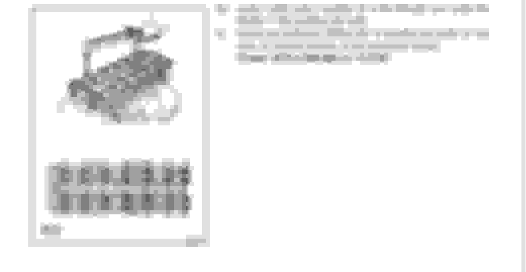
Now for some procedure both the MKIV Supra TSRM EG-62 under "ENGINE MECHANICAL" and the ARP instructions are followed.
ARP says their special thread lube helps achieve a consistent torque loading to the required setting. They want to see the nuts tightened in the Toyota sequence in THREE EQUAL STEPS to 80 ft-lbs.
I chose 40 ft-lbs for pass 1, 60 ft-lbs for pass 2 and 80 ft-lbs for the final pass 3.
Gerrb did advise me to do 85 but... well... I chickened and stuck to the ARP recommended 80 ft-lbs instead. Gerry, if I've actually done wrong... I can get in there again and to one more pass. But come to think of it that would violate ARP's instruction of THREE passes so in actuality I'd probably have to properly relieve the head studs and start all over again before reassembling what would be needed to get in there (plus the camshafts).
Anyway, I was not about to use any old torque wrench for this job. I used the recently bought CDI 20-100 ft-lb torque wrench which I know is in very good calibration.
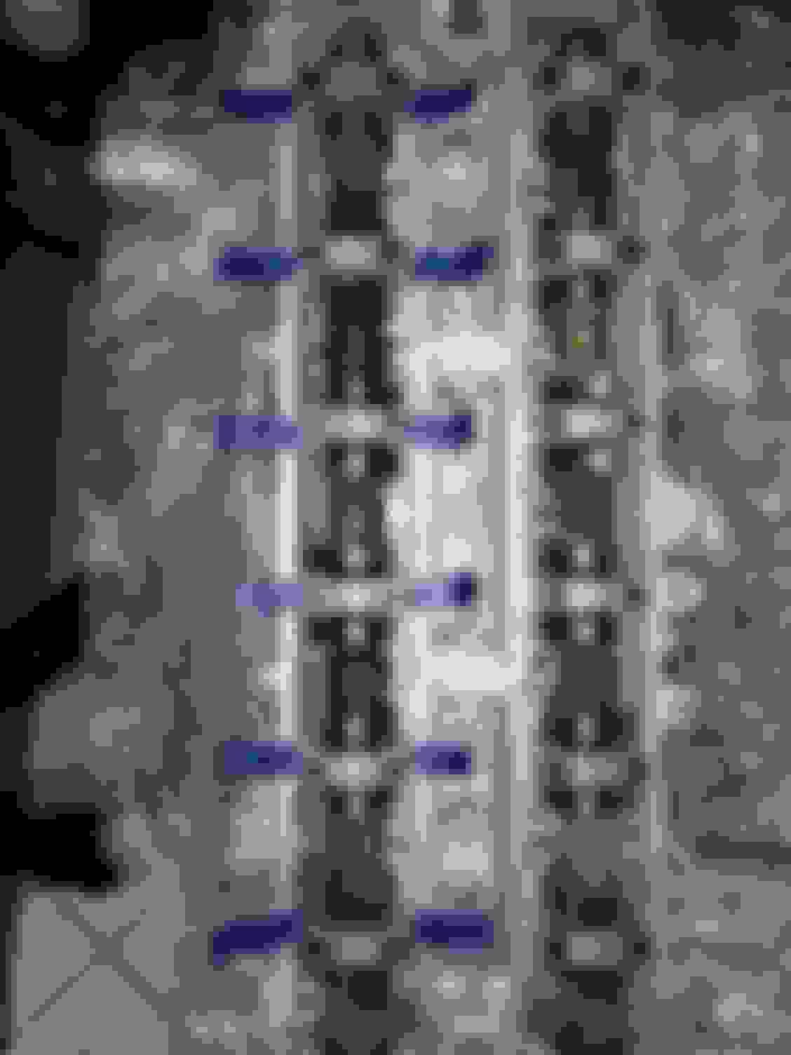
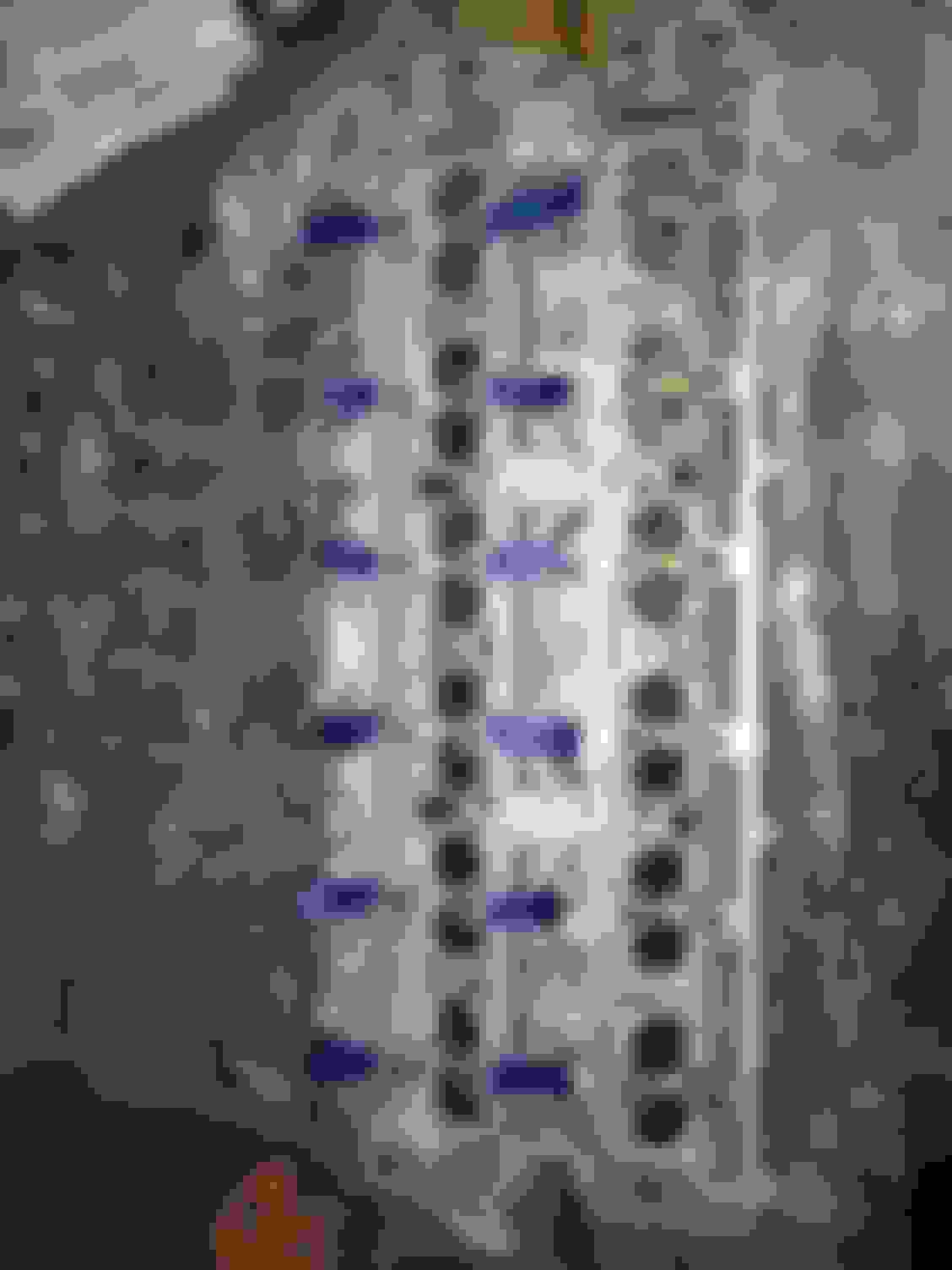
As before, I labeled each head stud location with blue painter's tape with a number to keep track of the correct torque sequence. To be absolutely sure I was doing it right, I would say each number that was just torqued as I went through 1-14. That helped me be completely certain I hadn't missed anything along the way or left the order.
The actual torquing did not take very long to do once things got started.
Here is the manual page with the torque order:
......
Coming next: camshaft and valve cover installation.
Craig - you are good with 80ft.lbs of torque. Following the ARP studs instructions is alright. It is just that due to the RPM I am revving my cars to get into the desired power I am aiming , an extra 5ft.lbs. does help keep that head down without being lifted. Well , these are small tips I get from well known Supra engine builders who do not strictly follow things by the book but seeing cars they build and how they perform , I couldn't help but pay attention to what they say. Experience in my opinion always trumps what you learn from the book , ! After all every good invention was never found in any book , it is a result of experiment and experience.
Thank you Gerry! I had hoped I would be all right sticking with 80 ft lbs. And I did use a brand new calibrated 20-100 ft-lb torque wrench to be sure it was accurate. I had the valve-train rebuilt to factory Toyota specs with a mix of evaluated existing valvetrain parts and OEM valvetrain parts that Driftmotion decided I should replace. My rebuilt GTE head is only set up for the stock 6800 RPM redline.
For what you are doing with your 2JZGTE's I would not question the wisdom of those experienced and well known builders over by-the-book specs. Indeed a lot of development has been achieved with these engines well beyond Toyota's original specifications resulting from experimentation and trail and error over 20+ years
That said, I know I would not have done any harm by going to 85 ft-lbs either
In my case when I had the head rebuilt I opted to have it re-shimmed to stock specs with the factory cams and so I will be skipping any steps regarding solid lifter shim measurements and ordering of the correct sizes.
I started with the intake camshaft. Before lifting it into place I liberally covered all the lifters and cam mating surfaces with Permatex Ultra Slick Engine Assembly Lube. Goopy stuff with the consistency of thick syrup.
Now what I should have done next, according to the TSRM and at least one 2JZ engine build video I've seen, is to lube up and install the camshaft seals BEFORE installing the front cam caps. I didn't do this and honestly I can understand why it is not only easier to install the cam seals before the cam caps but also how it is better considering how the Toyota FIPG that is required for the two front cam caps might get in the way. Once the front cam caps are installed with the FIPG applied you will want to get the cam seals in before it cures completely.
In retrospect I would install each cam seal before torquing down each cam cap.
The procedure for camshaft installation in the MKIV TSRM will be in EG-64 "Engine Mechanical".
As before with the camshaft removal and the cylinder head studs, the correct sequence for each camshaft is VERY important.
The torque for each bolt is 14 ft-lbs. For this I used the lower range 5-75 ft-lb CDI torque wrench. Another one of the critical torque measurements for an engine build that I wanted to keep as accurate as possible.
Again I used blue painter's tape with a number label for each cam cap bolt's position in the sequence.
For the very front cam caps a little bit of Toyota FIPG (Form In Place Gasket) is needed as shown in the TSRM diagram above. As mentioned above, it actually does make sense to install the two front cam seals first before installing and torquing down the front cam caps with fresh, malleable FIPG applied to them.
Now I loaded all of the camshaft contact surfaces with the Permatex Ultra Slick assembly lube but even after installation I felt some more applied to the lobes and lifters would be a good idea.
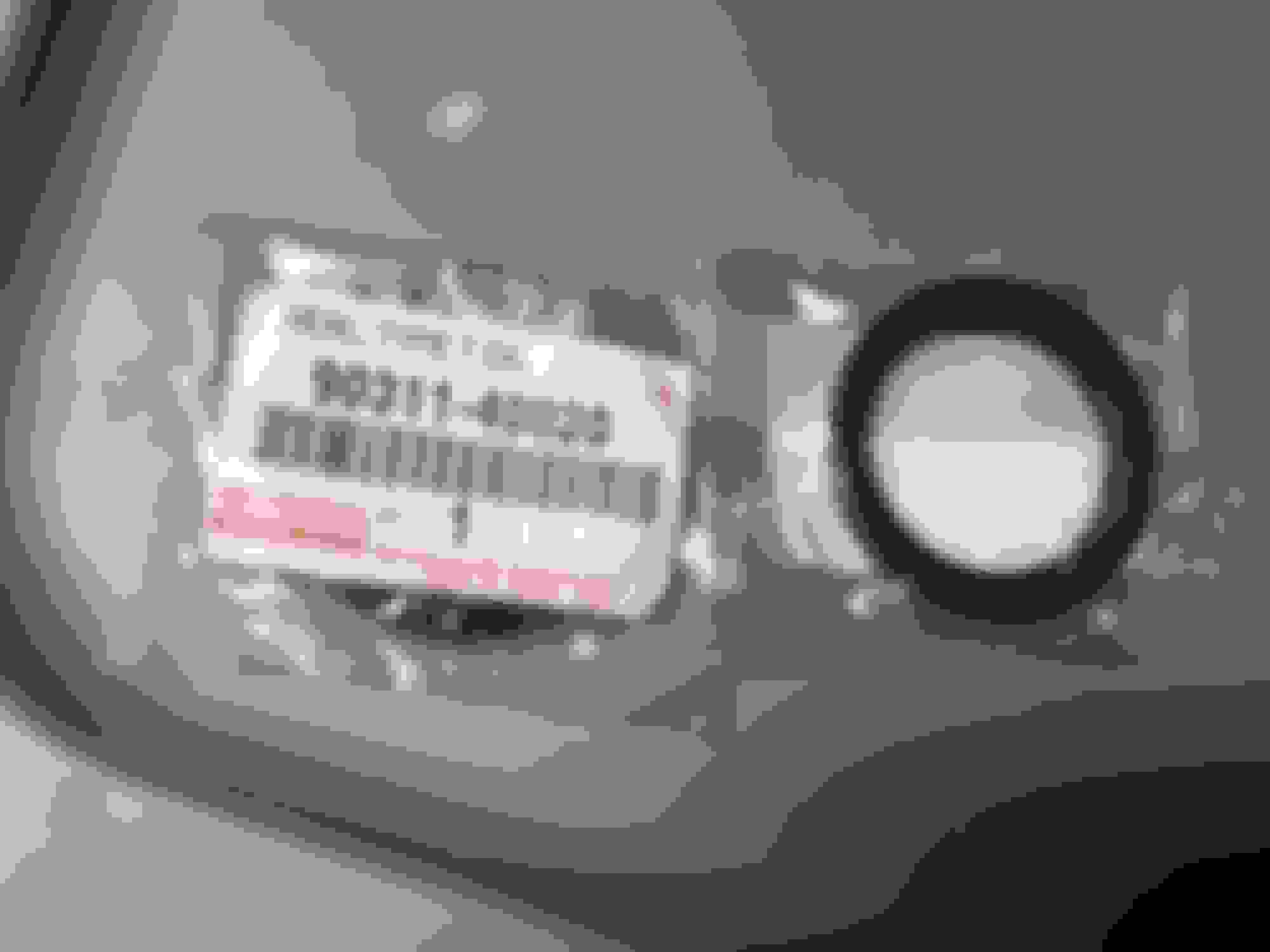
In this last picture the cam seals were not yet installed. I didn't grab a shot of that before I finished this stage. The two (2) seals (P/N 90311-40020) were lubed up on the inner and outer sides and carefully pressed in with a dull rubber end of a small screwdriver and a rubber mallet. If I had an appropriately sized socket to press around the cam seal ring evenly that would have been ideal.
The metal rear cam cover plate (P/N 11325-46032) goes on with four (4) bolts (91621-60612, superseded to 90080-11589). The bolts are torqued to 78 inch-lbs.
The GTE cam gears (or whatever aftermarket adjustable cam gears you prefer) go on with two (2) large bolts (P/N 90119-12212). They are torqued to 59 foot-pounds as outlined in the MKIV TSRM EG-66 "Engine Mechanical"
Toyota specifies either a hex wrench onto a specific part of each camshaft to hold it in place... or with the valve covers on you can use a Schley #96800 cam gear holding tool (in place of the $500+ Toyota Special Tool).
If you wish to use the wrench on the camshaft holding method you will need a very thin wall adjustable wrench or a fixed wrench in (I think) 31mm. I tried everything from 28mm, 29mm, 30mm and 32mm and it seems the oddball 31mm size should be about right. Unless there is a good non-metric size to use instead.
I hand tightened my cam gears at first and tightened down the bolts with the Schley cam gear holding tool later but the pictures are shown here for the sake of keeping order in this thread.
The valve covers were temporarily set on for some of these pictures.
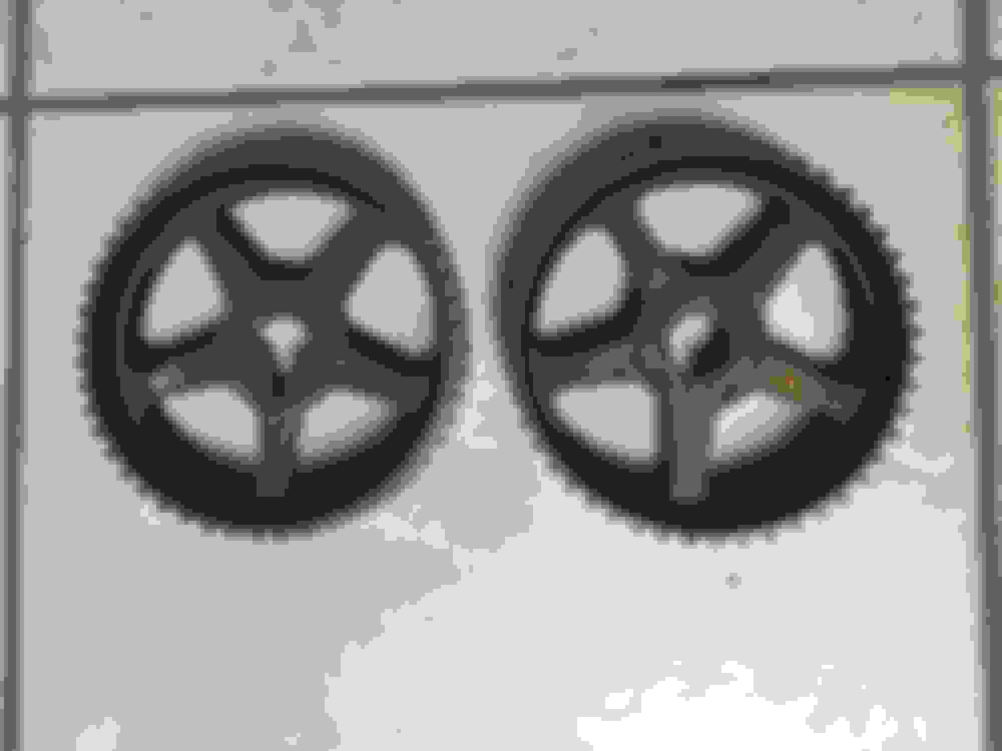
Oil Pump Timing Drive Gear & Setting Top Dead Center & GTE Valve Covers Install
For this build I needed to buy a 2JZ-GTE 24-tooth crank timing gear (P/N 13052-46010).
This is the standard Toyota OEM gear. It is a common thing to purchase one of these with the metal start ring tack welded in place (such as the one PowerHouse Racing offers) because that wheel has been known to separate from the gear section in high horsepower applications. Since my build isn't going for more than a max of BPU horsepower I think I will be fine without the extra tack welding.
There was just a tiny bit of deformation on one of the two keyways on my engine's crankshaft that prevented getting the gear on so I took a common disposable (ie: non-metal) nail file and carefully worked on the barely damaged area until I got it nicely uniform and smooth. I would not use anything more severe than this. A common household disposable/paper nail file is well enough to fine tune a crankshaft keyway that has extremely minimal deformation.
Once I got the keyways made uniform again the timing drive gear went on with some light tapping from a rubber mallet.
Setting TDC
Before I went any further I needed to set my camshafts and crank at Top Dead Center prior to installing the valve covers.
I did this slowly and carefully so as to be extra careful in case the valves ever hit a piston... although as far as I am aware a stock 8.5:1 2JZGTE Non-VVT-i engine is non-interference and this should never be an issue.
I couldn't find a suitable wrench that was both thin on the outside and the (I think) ideal 31mm size to grab the hex section of each camshaft.
Instead I made do with a 32mm crow's foot I had and a breaker bar. It wasn't perfect but it was close enough if I grabbed at certain angles.
I turned each cam clockwise until I could see the mark on the cam gear lining up right with the little metal crease/mark on the metal back timing cover plate.
Then I took a spare used 2JZ crank pulley bolt, screwed it into the crankshaft and put a wrench to it to turn the lower piston assembly clockwise until the mark on the crank timing drive gear lined up with the little TDC mark on the oil pump cover.
Now that the TDC had been set...
Valve Covers
I previously had my 2JZ-GTE Non-VVT-i valve covers sonic cleaned and powder coated with an OEM-like finish and I'd removed the rotted PCV gasket fitting.
Since it's the top of my engine I wanted them to look nice
From the MKIV TSRM Section EG-18 Under "Engine Mechanical"
Two studs go in the very front middle locations and two go in the middle locations at the very end of the cylinder head. A 5mm socket is used to screw them in by hand.
I lightly covered each valve cover gasket with the lighter consistency Lucas semi-synthetic engine assembly lube and pressed each in to the appropriate cover.
I laid down four beads of Toyota FIPG on either side of each front cam cap as shown in the diagram below.
The valve covers go down onto the studs and then the rubber insulators go onto the studs and under each screw, rubber side down to protect the cover finish.
They are torqued to 48 inch-lbs.
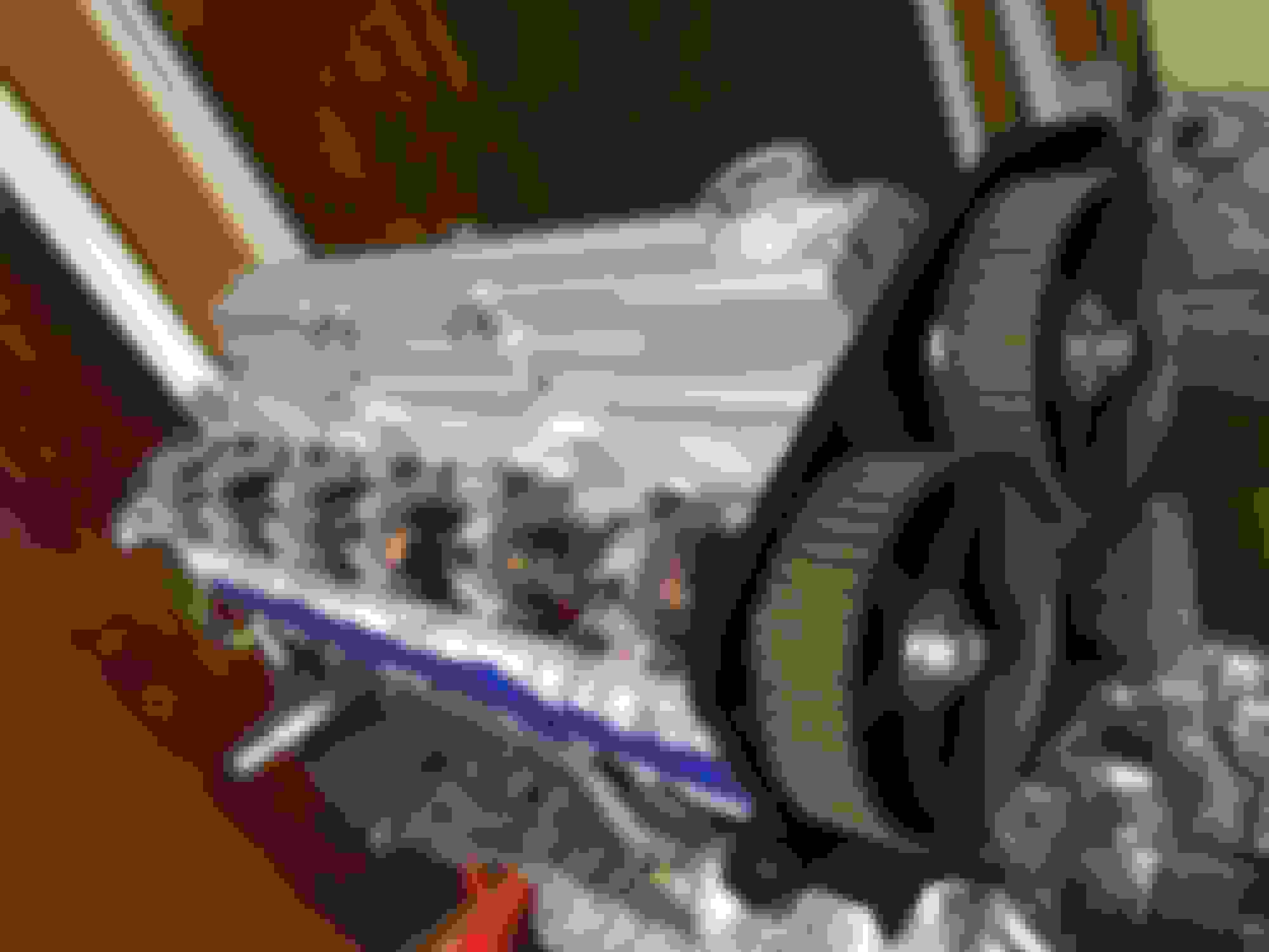
A shot of the engine with just one of the valve covers fully installed. The other one was finished just after this was taken.
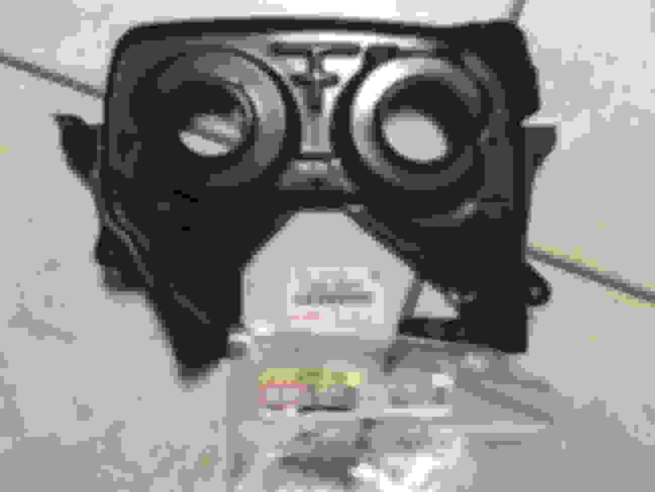
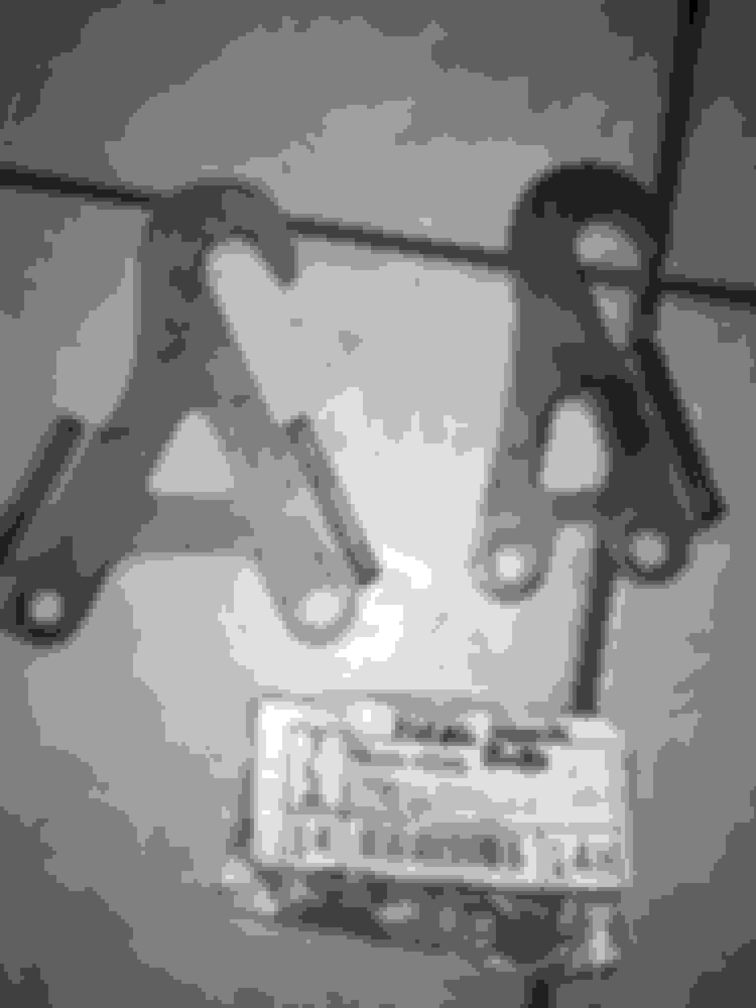
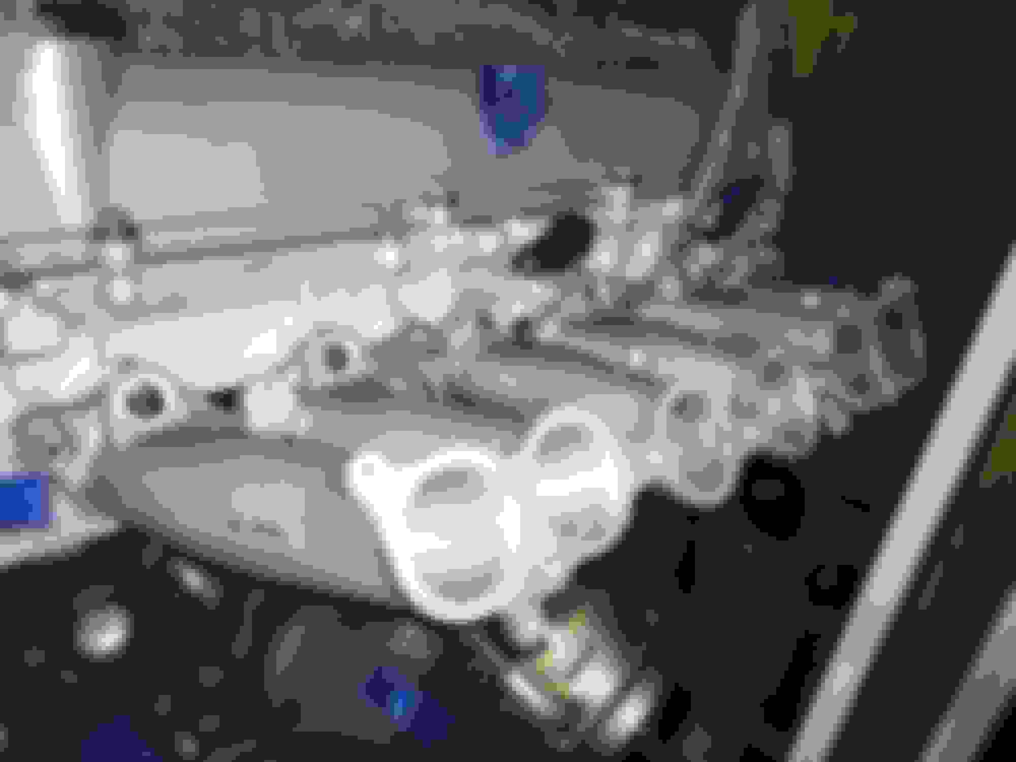
Short deviation from the thread flow. I'm looking for a couple of hard to find parts. One is the metal bypass pipe that goes onto the intake manifold and connects one port of the 2JZGTE Idle Air Control Valve to the underside o the throttle body (and that connects to the cylinder head).
Anyone have one of these?
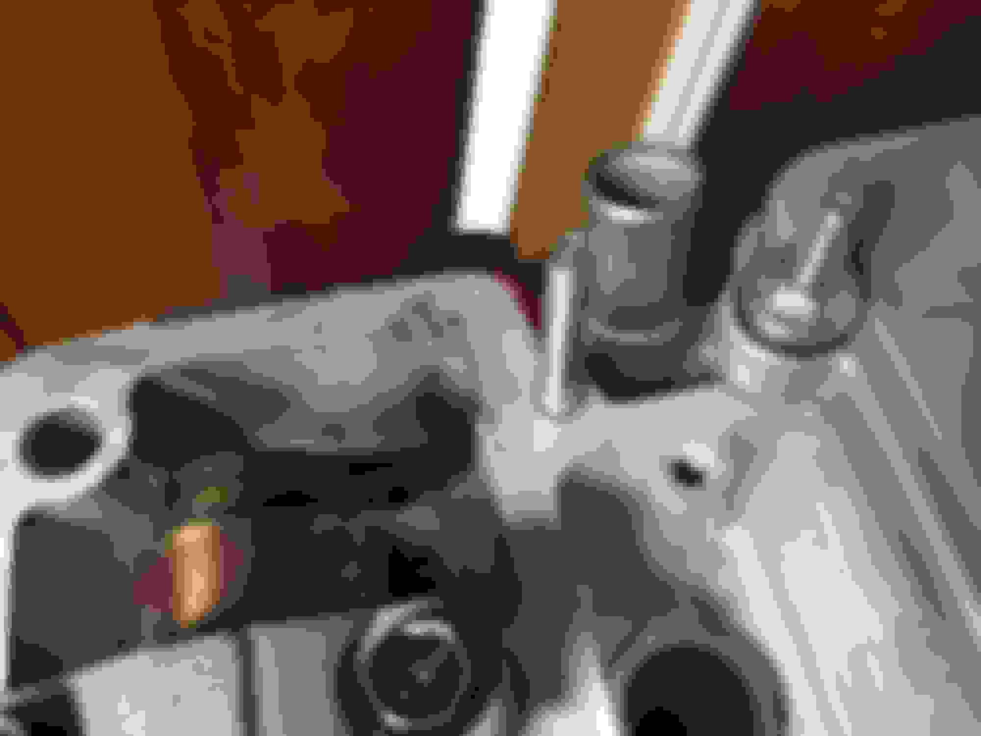
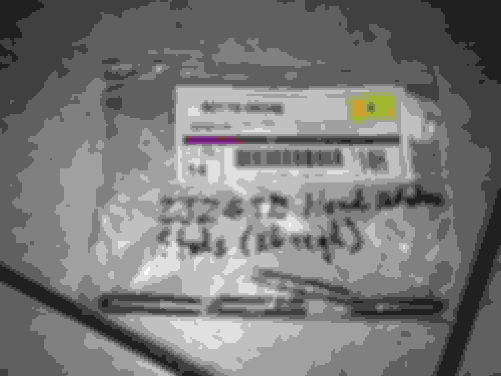
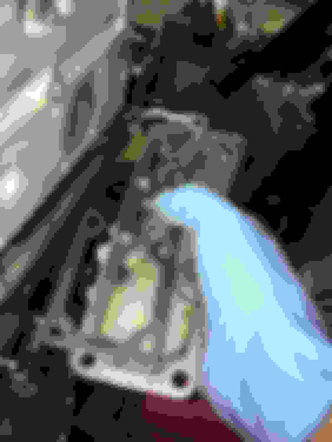
Then there is another oddball, the upper 2JZGTE intake manifold "STAY". Not really critical but I'd love to pick up one of these if I can. It's a very small specially formed metal plate that stabilizes the intake manifold to the cylinder head.
It goes here (where I am pointing). In the upper left side of the image frame and out of focus you are seeing the throttle cable bracket.
Edit: I found each of these! Addressed in later posts.
Coming back to my build thread after a long break. There is a lot of documentation to catch up on and between my father's illness earlier this year (he's fine now) and a mountain of work I came back to I couldn't wrap my head around this for a while. Apologies, all.
Cylinder Head Hangers (Hoist Hooks)
From where we last left off having installed the camshaft gears and valve covers, the GTE engine hooks go on. These are no longer available from Toyota so I picked up a used set.
Bolts are 90105-90345 (x4) and they go on with 29 ft-lbs each. Note that the one last bolt on the intake side rear has to bee loosened later and re-torqued to affix a ground strap from your engine harness (GTE).
Important 2021 Edit Note: You must create a separate cylinder head ground wire for the cylinder head at this time!!! The cylinder head requires its own separate ground wire according to the Toyota Supra Turbo wiring and electrical TSRM. The connection to the cylinder head according to the Toyota service manual is the rear-most bolt of the rear cylinder head engine hook.
--I suggest picking up some 8GA copper stranded wire (marine tinned is fine) from a marine supply store.
--Use a 5/16ths or 3/8ths inch eyelet ring terminal that accept the 8GA wire (10GA wire and matching ring terminals is probably fine also but I would not use anything smaller and I still recommend 8GA) for the cylinder head bolt side.
--For the chassis connection at the firewall just next to where your engine harness plastic cladding bolts up to there will be a spare unused bare metal spot to fit a standard 10mm bolt (Toyota P/N 90119-06512). This end of the 8GA wire will need a strong 5/16ths eyelet ring terminal that can bend just a little).
--It does not need to be a very long ground wire-- just enough to have some slack to work with when installing or removing the engine later.
--Apply heat shrink tubing to both terminal ends for added protection over time.
--Bolt the cylinder head engine hook end of this ground wire connection on WITH the rear cylinder head engine hook's rear-most bolt NOW before installing other hardware such as the Idle Air Control Valve which will make accessing the bolt difficult later.
Now leave the other end free and continue the engine assembly. You have just saved yourself a lot of trouble down the road to ensure you have a strong factory location cylinder head ground.
This is not an optional step. You can, if you forget to do this before installing the engine, later on remove the idle air control valve to access that engine hook bolt... or you can install a longer 8GA ground wire at the side of the cylinder head on the intake side just next to and behind the GTE throttle cable bracket. However the rear engine hook bolt is the correct location that Toyota specifies.
Not having any sufficiently sized ground wire attached directly to the cylinder head can potentially cause electrical issues down the road. It's best to do this step now and make a strong wire/terminal connection that will last many years.
Intake Side Studs
Next, onto the cylinder head go the intake side lower mounting studs. 90116-08348 (x6). They should go on with a 5mm or 8mm socket fitting or small wrench.
Timing Belt Tensioner, Idler Assembly and Crank Sensor
Jumping to the front of the engine now, on goes the timing belt tensioner, timing belt idler pulley and the crank sensor on the oil pump.
Follow the Supra MKIV TSRM EG-32 and EG-33 "ENGINE MECHANICAL"
HOWEVER, DO NOT REMOVE THE PIN AS EXPLAINED BELOW UNTIL YOU HAVE FITTED THE TIMING BELT!!!
Idler Pulley Installation
The idler pulley 13505-46041 goes on with the special bolt 13556-46010. I used a bit of assembly lube on the center of this bolt before sliding the idler onto it and bolting it in.
25 ft-lbs is required for the idler pulley bolt.
For me, there was a bit of uneven entry with this bolt. It wobbled in as I tightened it with a big hex bit on my socket wrench. It wasn�t so much resistance as it felt like something was lopsided in alignment. I almost stopped and thought of returning the bolt for another one but these were all new parts and I knew the threads in the oil pump had never been used before.
I pressed on very carefully and everything finally settled perfectly straight and was much easier to finish in place. No binding at all and nice, smooth, free movement.
Follow the MKIV TSRM EG-30 "ENGINE MECHANICAL"
And in EG-121 the crankshaft position sensor (located on the oil pump) is installed with 78 inch-lbs
Since my build is going to use the factory EGR system I have to reinstall the cooler plate and gasket to the rear of the GTE cylinder head. I had the original plate sonic cleaned a while back, leaving it nearly as clean as the rebuilt cylinder head
I can't say the same for those original bolts, however.
FYI, new OEM EGR cooler plate bolts from Toyota are P/N 91511-60620 (supersedes to 91511-B0620).
Sometime after these pictures were taken I went through these and replaced every old bolt with a new one for cheap insurance.
In the MKIV TSRM EG-61 "ENGINE MECHANICAL" the eight bolts are specified to go on with 78 inch-lbs.
And here is a later shot with the new EGR cooler plate bolts installed to replace the old ones:
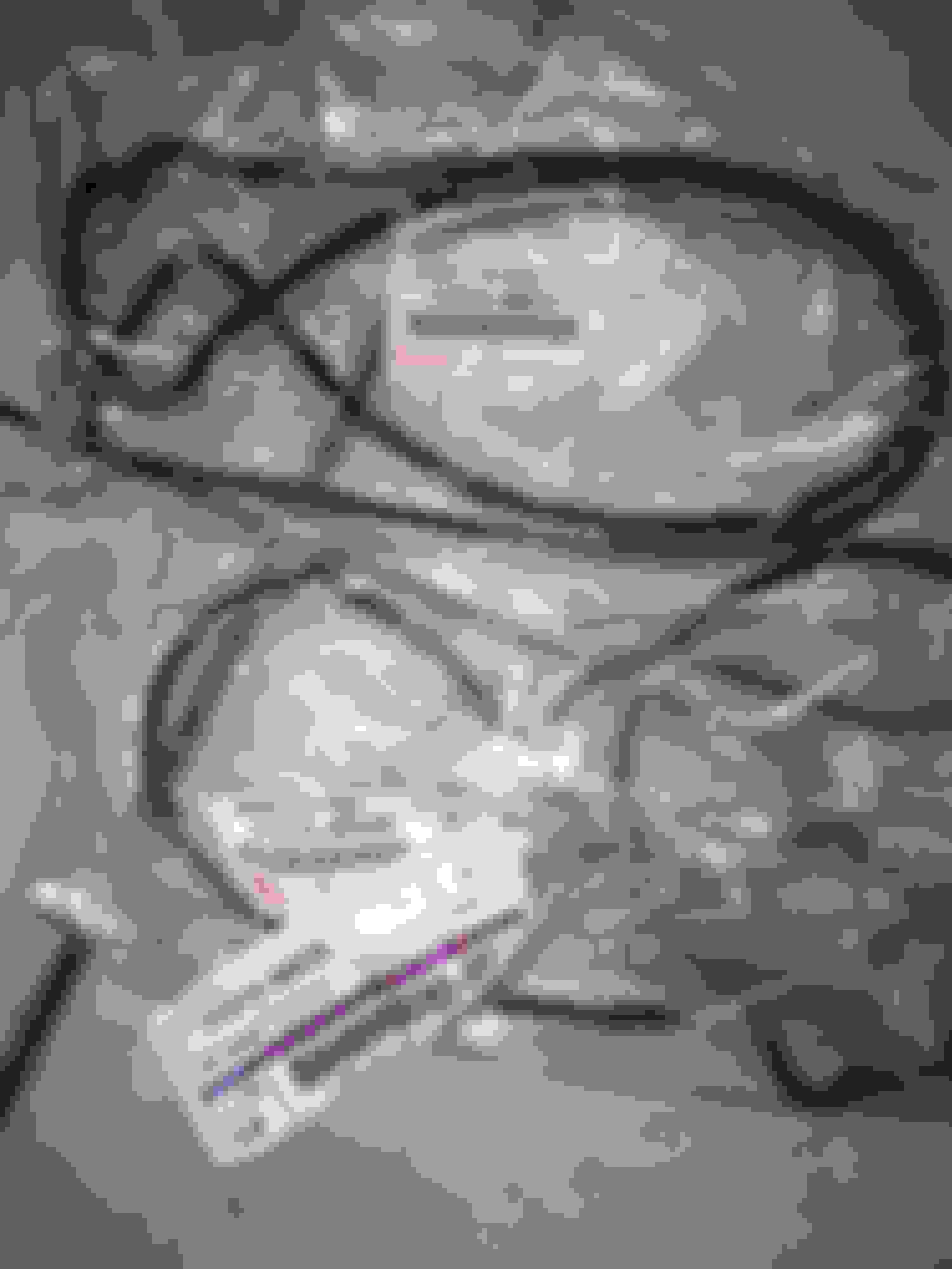
Pretty simple. Hoses 12263-46010 and 12264-46010 both go onto their own specific ports just over the spark plug and coil galley. No clamps, just press them on.
GTE Cam Sensors (on cylinder head intake side)
Two of these sensors (90919-05007) go onto the middle and rear intake side of the GTE cylinder head. Each takes two 90105-06011 bolts. Torque them down with 78 inch-lbs of torque (very little torque).
Follow the MKIV Supra TSRM EG-62 "ENGINE MECHANICAL"
GTE Valve Cover PCV Valve w/ Grommet
After the nightmare of carefully digging out a hardened and crumbled original PCV valve grommet from the valve covers prior to getting them cleaned and powder coated the reinstallation was a cinch. The PCV valve that came with the covers still sounded ok but I opted to install a brand new one from Toyota anyway. I picked up a new OEM grommet and a spare just because.
Installation is extremely easy. Pop in the new grommet and then pop in the PCV valve. Cover the end of the valve with some painter's tape for until it's connected with a hose.
Timing Belt Installation (w/Holder Plate and Guide Install)
Unfortunately I did not take photos of this part of the build so I'll just post the TSRM procedure here. Once the belt is on the cam gears and everything is set (it will be tight) then you can release the pin on the timing belt tensioner.
Make sure the marking points on the oil pump and crank gear and the marking points on the cam gears and metal cam cover plate behind it are lined up to TDC. Always turn the engine CLOCKWISE.
Then, make sure you install the small timing belt guide plate next to the crank gear.
Outlined in MKIV TSRM page EG-66. The OEM gasket is 17177-46031. Studs go into the cylinder head and the nuts are torqued to 20 ft-lbs.
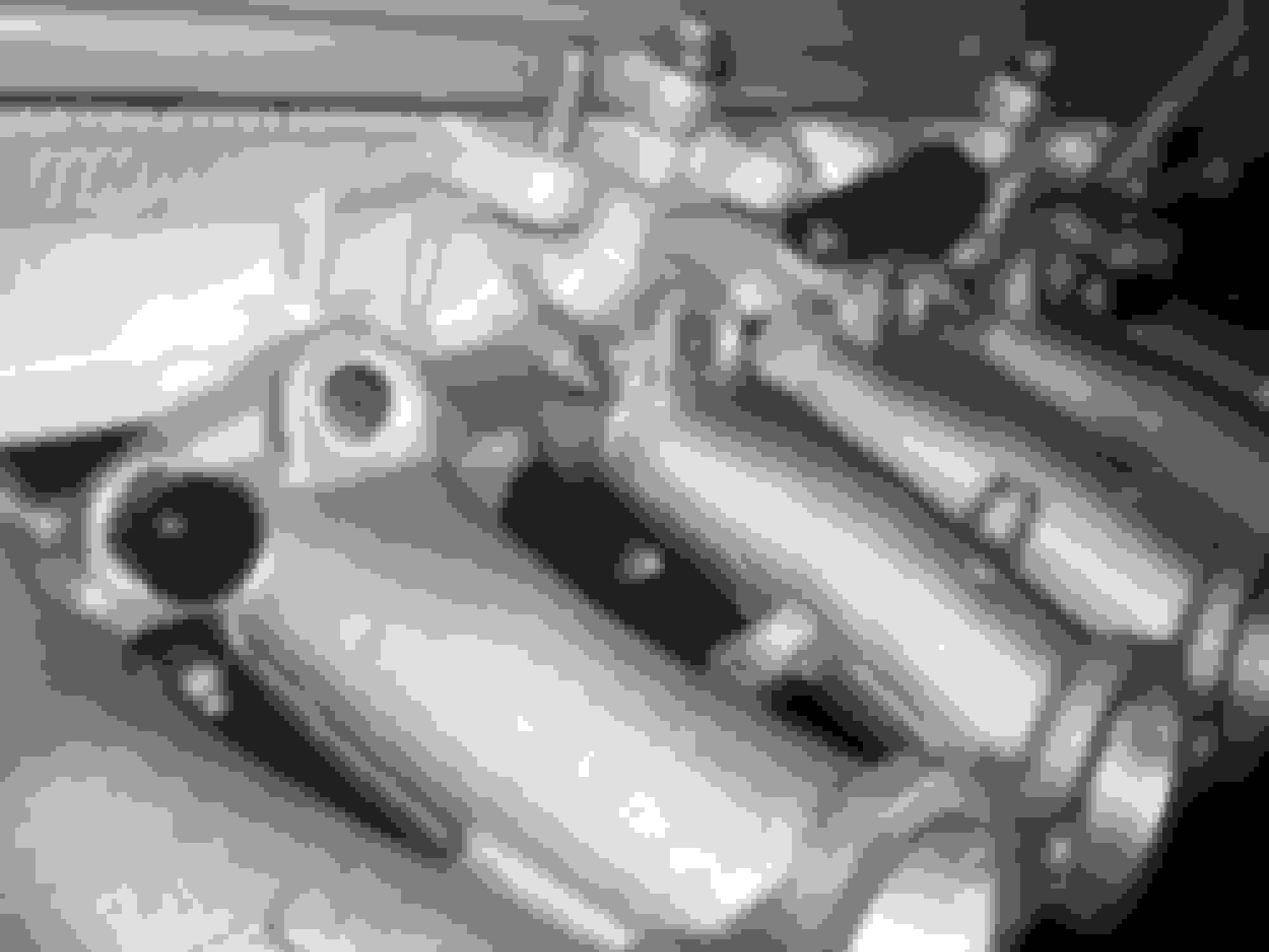
Fuel Injector Rail and Fuel Injector Installation
First these two hard plastic spacers go into two retaining slots on the lower intake manifold.
Then these six O-rings go onto the USDM GTE fuel rail in each spot below where the injectors rest.
Then the injectors go into the rail very snugly. The front most injector pulse connector gets turned upside down whereas the others face up. Six more O-rings go on top of the injectors and are held down by three metal plates. The plates go in a specific orientation and are held down by 10mm bolts with washers.
I picked up these USDM 550cc factory injectors on eBay a couple of years back and had Driftmotion do testing on them. The seller claimed they had already been cleaned and balanced but I wanted to be sure. They had good flow and pulse numbers across the board!
The TSRM Manual Pages are EG-278-279 under "SFI SYSTEM (2JZ-GTE)"
And when everything is bolted together (minus those metal retainers and noting that I forgot to re-orient the Cylinder #1 injector connector upside-down in this photo), voila!