When you click on links to various merchants on this site and make a purchase, this can result in this site earning a commission. Affiliate programs and affiliations include, but are not limited to, the eBay Partner Network.
Retroplay, a couple of comments on your (minor) issues:
>> The map lights do have the positive and negative terminals reversed. Why? I don't know. It didn't make sense to me either but rewiring the mirror/light mount looked like a pain to me. So I wound up finding a guy on ebay who sells BA9 LEDs and matched up the Lumens ratings to an incandescent. The best part of the story is that he would sell the LEDs with reverse polarity. So I bought those. They look great.
Well, probably just didn't really matter. Incandescent doesn't care about polarity. I thought about just flipping all the LEDs around but that actually seemed more of a pain than rewiring the map light. It actually wasn't THAT bad. When I take it out again, I will take pictures of what I did and explain how.
Essentially it is just swapping the lines that are going to the socket connectors, but that required moving and resoldering some wires and then adding a new common wire. Having a plan going in is important because it would be easy to cause a short and damage something if you don't wire it correctly.
Obviously you cannot just swap the wires in the connector because of the door switch.
It is a simple OR circuit. If the center switch is in the door position, the door will ground that line when you open it. This allows current to flow through those diodes and bypass the manual switches.
So basically I removed the little wires which went to one end of the switch and and wire to extended them to make a new common line going between them. Then I split the wire that is the common in the diagram above and rewired them to the switches.
This swapped the polarity of the sockets. And since incandescent doesn't care, the original bulbs still work just fine.
I was all done with doing this before my friend suggested the RGB idea which made it pointless since I won't be using the sockets at all anymore.
Also note that the illumination voltage is ~8V, not 12. So with these aftermarket LED lights we are not getting their full brightness because the resistors are chosen for 12V. I was not impressed with the LED replacements that I bought.
Yes, rewiring was a potential solution for me but just purchasing LEDs that are already reverse polarity was a much simpler solution.
I could have sworn that I measured the voltage there and it was full battery voltage (12 V) not 8 V but I'd have to go back and recheck for sure. That was several years ago when I did it. The LEDs that I installed are as bright or brighter than the original incandescent bulbs.
I think that it is really cool that you are attacking the entire sound system bus link. I looked at that after I first got the car and came to the realization that I didn't have the time to deal with a project that extensive. (Also, this was before the Arduinos came out.) Cool project, sounds like fun. Best of luck to you.
Since my goal is to keep the car looking as stock as possible, before I mod anything I usually buy a replacement part to modify just in case the mod goes badly or I want to return it to stock for some reason. I then clean up the original parts and store them away.
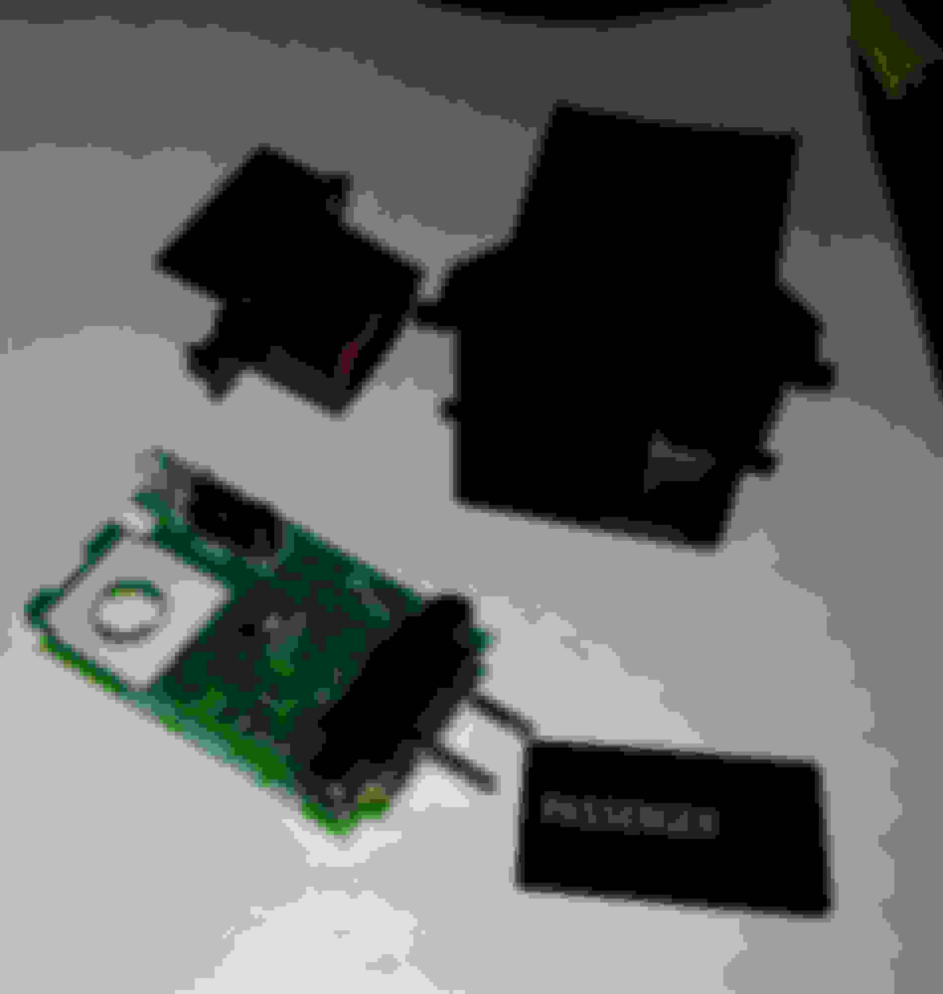
So, a few updates today. I received the passenger seatbelt warning assembly today. And it was what I was hoping - just a lamp going between ACC and the passenger seatbelt switch. The connector is 6 pin but only two of the pins are populated in the connector. The harness side probably has all pins. The circuit board looks like it was intended for more features, but it only contains a diode, a resistor and the LED.
Here's some pics:
The original Part
The individual parts torn down
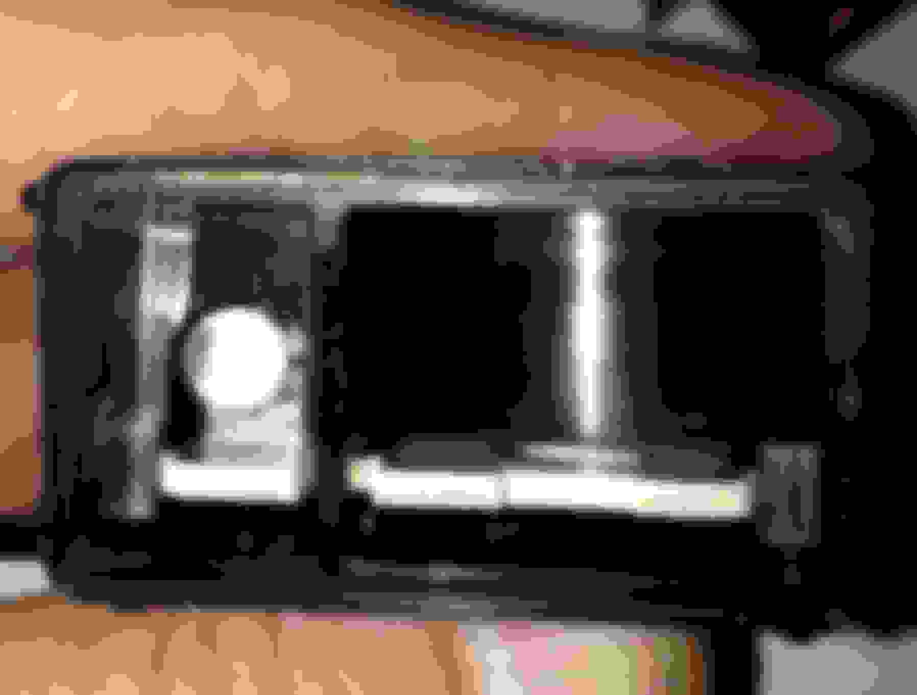
With front removed. You can see it is separated into two compartments. The other side would have lined up with the incandescent lamp socket.
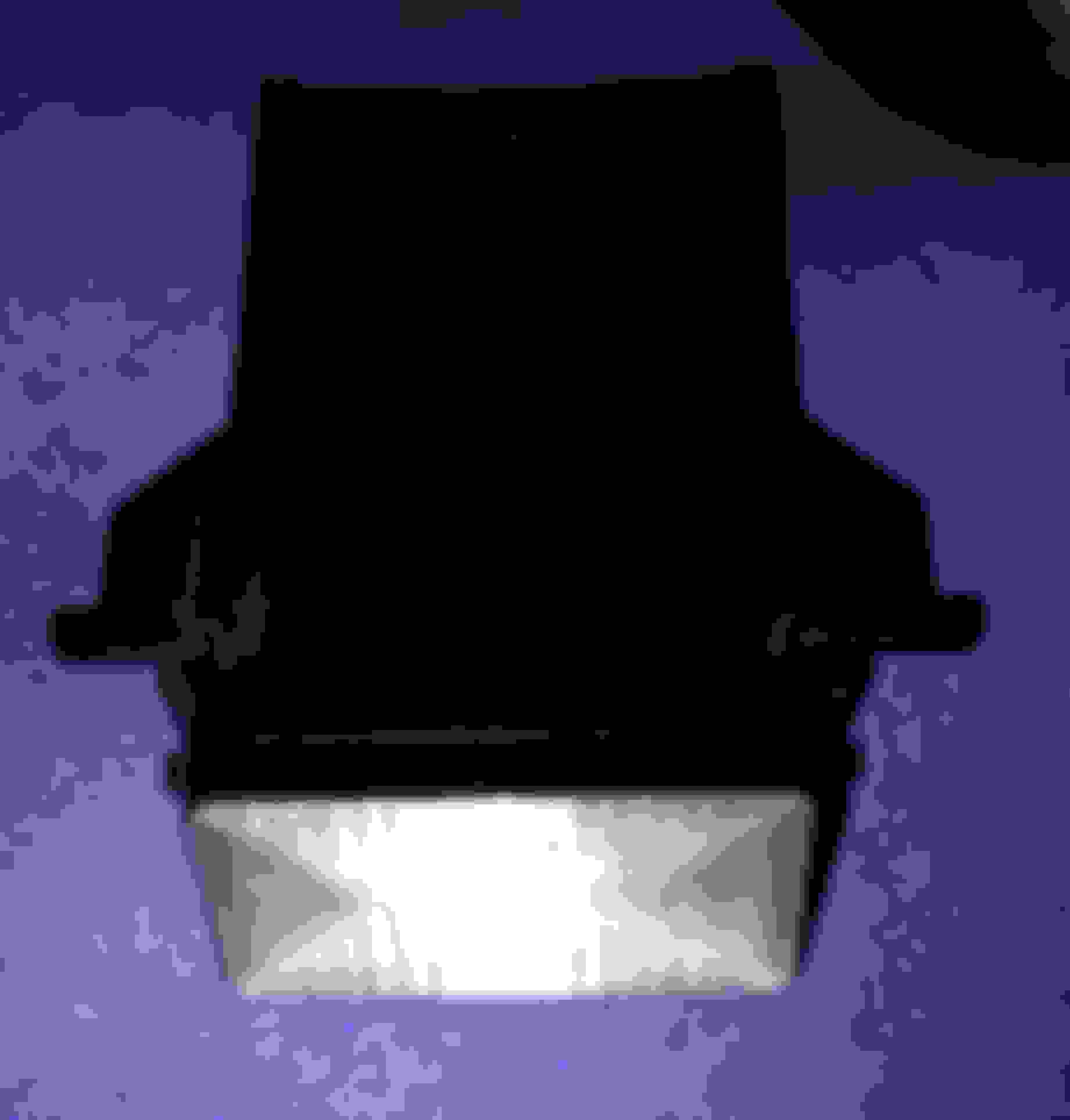
Test fitting a new lens. Printed in clear for light to shine through. I was a bit surprised I got it perfect the first time.
The new lens will be first painted with a thin layer of frost paint. Then it will be masked off for anywhere I want light to shine through.
Given how much room I have in there, I am trying to think about what I want to put in there and could really use some ideas or suggestions. The only pre-determined thing is a USB charging socket. Obviously being on the passenger side, whatever ends up in there should be for passenger convenience. Any suggestions?
Here are the dimensions of two configurations that I am considering (Horizontal or vertical USB port.) The LEDs in the horizontal drawing are just for a demonstration of size. They would fit 3mm LEDs. I am leaning towards the vertical configuration because it looks almost too perfect to fit a USB socket.
As you can see there is plenty of room in there. Any suggestions? For those than don't think in metric, the dimensions are about 1/2 inch x 3/4 inch of the larger panel area.
I also took some pics of the NAV display internals today like I promised. I have confirmed that the composite video in and switch signal make it over to the main board. I have found the pin on the outside connector for the video in. Still trying to reverse engineer the switch signal. I have managed to trace it to an opto-isolator which would suggest that the signal goes to one of the outside pins (opto-isolators are used to protect the nav circuitry from spikes.) I have not figured out yet which pin it connects to. If it does go to the outside world, then grounding the signal would switch the display to composite input. No expensive gadgets needed to do it.
The switch signal does appear to also go to the main processor, so there would seem to be some reason for the nav display itself to switch inputs and would probably come from a command on the AVC bus. This is probably how Navtool, etc is doing it now. My theory is that it is intended for a backup camera since the NAV unit knows the direction you are traveling.
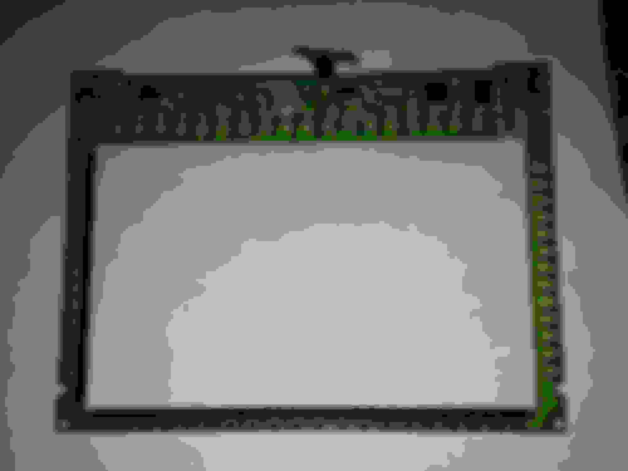
But, I am still planning to replace the LCD, so I tore down all the way to check for how a different 7 inch LCD would fit inside the touchscreen assembly and keep the protective glass (it's actually lexan not glass, with a film on it for UV protection, anti-glare, and anti-reflection) and touchscreen to remain compatible with the factory nav system.
I have a few different 7 inch LCDs in my parts bins and all fit just fine. I also tried the display of my Winbook TW700 7" Windows 8.1 tablet (these are going for about $60, btw) and it fit as well.
Now for some eye candy:
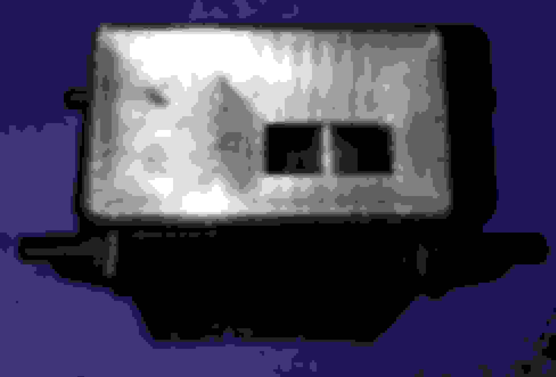
This is the original LCD. 800x480 STN TFT. This is why the viewing angle is not that great. Could really use an IPS display.
This is the touchscreen PCB. You can see all the Infrared LEDs and sensors. It creates a matrix of beams that are interrupted by your finger and interpreted touch positions in xy. I confirmed this does have its own microcontroller (datasheet attached) on it and the serial port (not RS232) for this micro goes out to the main board processor and also to that mystery connector on the top of the display.
The protective lexan screen cover with polarizing film
Test fit of a modern LED backlit 7 inch LCD. This is inside the protective plastic front assembly. Since the frame of a modern LCD is quite a bit smaller, it would need to be secured somehow within this frame.
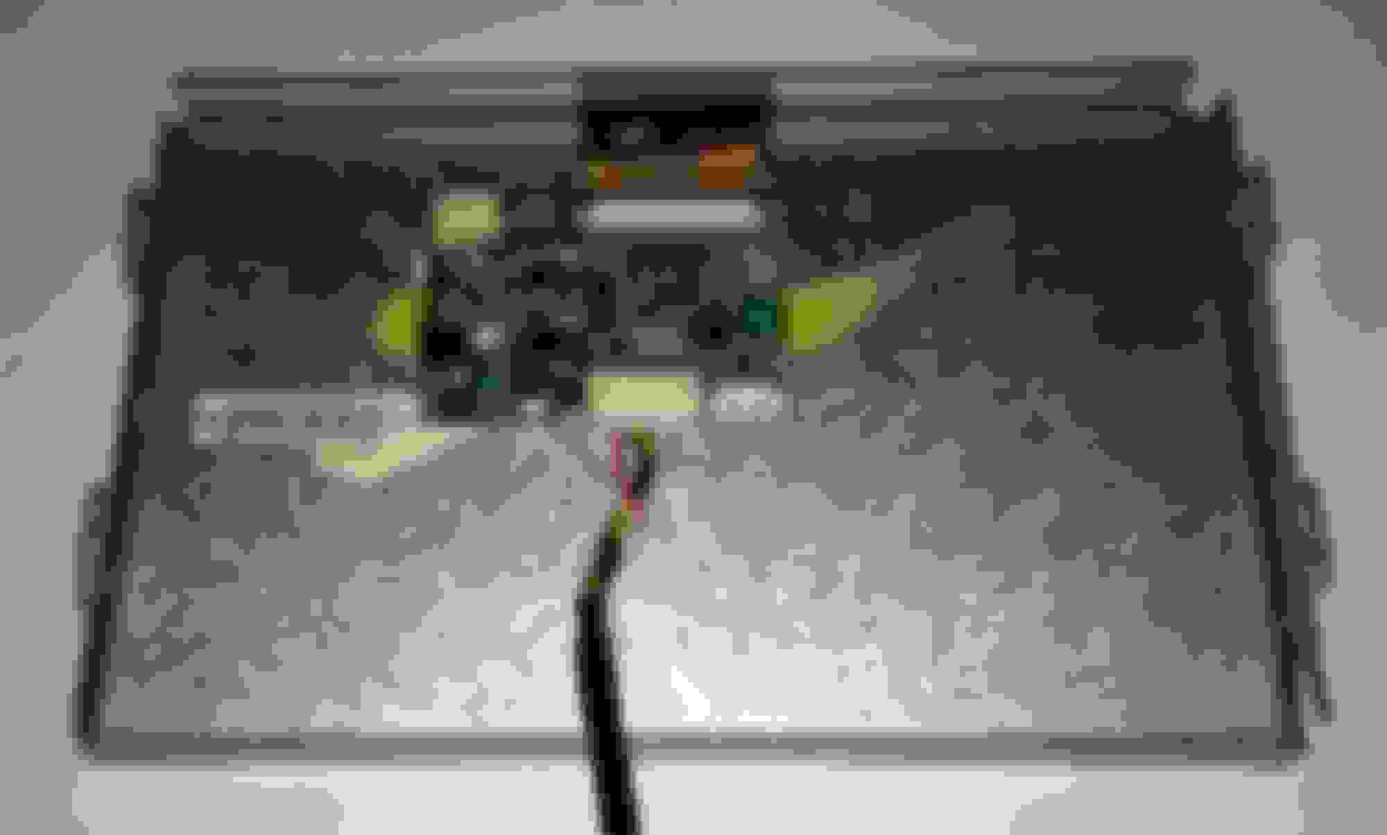
This is the LCD controller board. This is separate from the main processor board. It contains all components to drive the LCD by itself. The dangling connector is for power and control of the CCFL backlight from the main board.
If you removed this and the LCD, you would have just your average LCD monitor. The reason for pointing that out is that it is great news that this is independent of the main board. The main board is what connects to the nav ECU and the rest of the car. As far as it is concerned, it doesn't care what LCD is actually displaying the video. Shouldn't be too terribly difficult to swap in a new LCD and keep the original functions.
And this is the little magic IC that runs it all. It inputs the different video sources and converts them to the control signals for the LCD. The IR3Y29B has composite, S-Video, and RGBs inputs. The S-Video and Composite are considered one input. You could not have both. A single pin switches between RGBs (used by the navigation ECU) and the composite/S-Video input. I have attached the datasheet for this chip.
I realized that I forgot to take pics of the main board. I will have to add them later.
I have attached the datasheets for the LCD video processor and the microcontroller that is on the touchscreen assembly (for the nerdy folks looking here).
I almost forgot to add the datasheet for the two BA7606F chips. These are also important chips. They are video switchers. I think they are attached to the RGBs inputs so that the CPU on the main board can display its own info. With the nav screen on the bench, when you power it up with nothing else attached, it displays the Lexus Logo for a second or two.
Radio door button mod coming up soon. I am replacing the lamp with a blue LED and will be etching something else on the front of the button.
Here's the original PCB:
Back side with the polarity marked. I cut the trace going above the lamp socket and inserted a 330 ohm resistor in there for the LED replacement. Forgot to take a pic.
With socket removed
All of the lamps I have found so far are like this. Just little "grain of wheat" incandescent bulbs in these sockets with a green rubber cap over the bulb.
These are also inside the radio faceplate which will also be upgraded to blue LEDs later.
The LED leads are little too thick and putting them in these sockets puts a lot of strain on them. Since they are LEDs, there is no need for the sockets since the LEDs will outlast the car ten-fold. But, I tried it and while it worked, it dug into the socket contacts a little too much for comfort. I imagine the leads will rub through eventually from vibration and stop working. The LEDs will be soldered directly on the socket contacts.
I have removed the silver paint from the button and buffed it clear in preparation for painting and etching. I'll share more pics when it is finished.
I also have a complete center console with intact cup-holder and another ashtray/Light socket on its way. $50 for the whole thing. So, I can take a second stab at the ashtray area and will have a complete cup-holder again.
I have some mods in mind for the shifter cover as well, but that will wait for another day since you need to rip out the whole center plastic to get to the screws to take the cover off and I am not ready to do that yet. I am looking at some ideas for the coin-holder and want to replace the shifter lamp with blue LEDs. I will also likely paint the piece, possibly silver.
First up is the mystery connector I have been talking about. All signals go to the touchscreen controller.
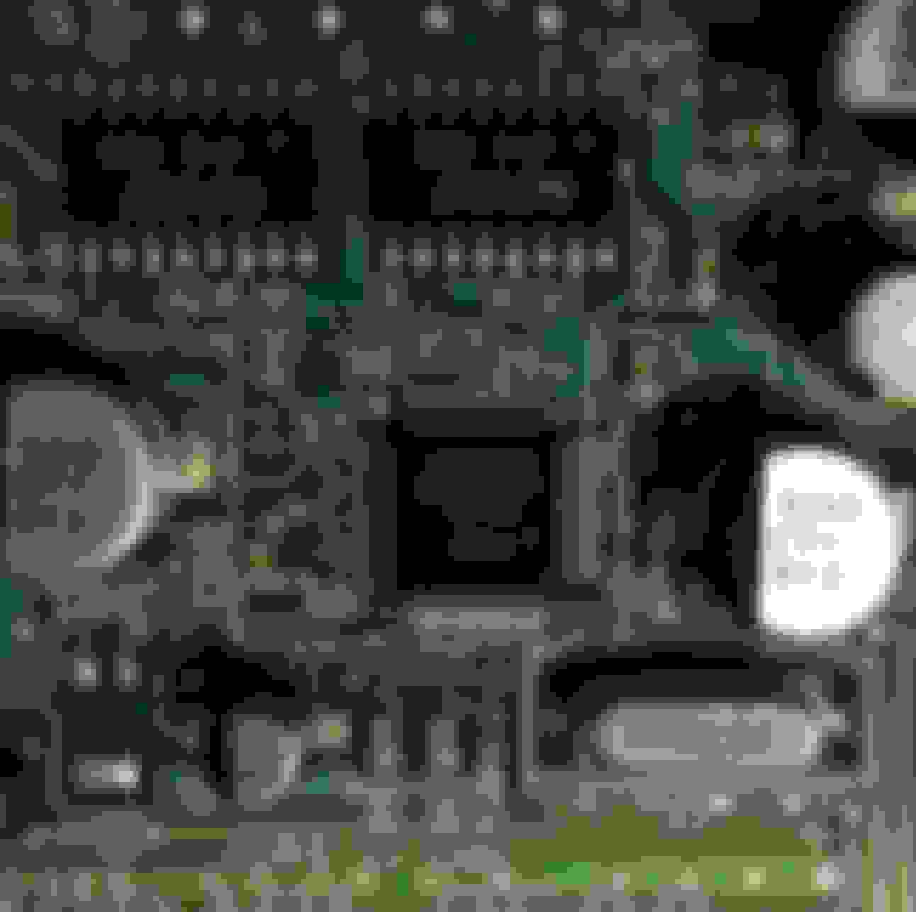
Top view of the main board. Only a few interesting things of note here.
Pro tip: when trying to reverse engineer something to do with video (well, besides HDMI and DVI anyway) - look for 75 ohm resistors (those 75R0 things.) Composite, VGA, RGBs, S-Video, and Component video all use 75 ohm termination and cables. They are usually placed as close to the connectors as possible. It's a dead giveaway where video is coming in.
Another pro-tip, when trying to figure out where power is coming in on some mystery device, look for the biggest capacitor near the connectors. The polarity of that cap will tell you which pins are positive or negative. Look at the voltage rating on the cap as well. A safe voltage to try first is about 1/3rd of the rated voltage of the caps.
Bottom side of the board.
Not much interesting here. The big chip is the processor and appears to be some propiertary ASIC. The chip next to is the flash memory with the firmware. A brave soul might dump the flash memory and change the logo that comes up. But we are in a Lexus car, so the logo is appropriate.
Thanks! Sometimes I feel like I am talking to myself when I am making these posts. I am glad some are enjoying it.
Man.. PLEASE DONT STOP!!! I read every update with awe (even though I don't understand it) !! I wish I knew how to tackle stuff like this. Cyber high five for you..ahh screw it.. bro hug!!
They are T3 or T4 wedge LEDs. A bit more spendy than doing it yourself, but this would allow you to go back to stock very easily. And I guess the time it would save you is worth the extra cost.
Here is what pinouts are known so far on the back of the Nav display. Compiled from various sources and my own measurements. I am pretty sure I know which group of pins are for RE1 and RE2 (the resistor network for the switches in the A/C control) since they pulse about once per second indicating that the display is scanning for buttons.
If you know any of the mystery pins I don't have filled in, please let me know.Those with a NAVTool seem to have a video cable plugging directly into the wire harness. I see it in pics people post, but never a clear enough picture to determine which pin it is going to or which harness. But, I am about 95% certain that pin 3 on the 6 pin connector is composite video in. All the rest on the six pin are known except the pin 2. I would need to de-solder the connector to trace it.
These pinouts are from the back of the nav display? I was comparing them to the beatsonic for the 02 sc430 and it shows a 22pin connector. Instructions show where the RCA video inputs are connected.

 09-11-15, 08:36 PM