
NA-T Questions?? Ask the Guru
 07-14-16, 10:42 AM
#46

this thread has a lot of info and pictures of mine in it.
https://www.clublexus.com/forums/per...-write-up.html
things I would do differently I already touched on, I would not cut the intake shorter and just use a RMR throttle body like you picked up. Everything else I have been very happy with actually. maybe a weld on bracket for the throttle cable but you can just use a little L bracket off the stud on the lower runner for where the harness used bolt onto.
are you bolting together to lower runner or welding? bolting works fine but welding is not a bad idea either.
If you are bolting on, I like to use a stud on the last bolt on the lower runner, it helps line it all up and it can be a pain to get a bolt in the last hole with your arm in the intake.

The following users liked this post:
666edric (09-04-23)
07-14-16, 11:27 AM
#47

With respects to the notable precedents, this should be named the ALI MOD. I mean seriously, there's so much info and support that Ali has provided that nobody else can/ or is willing. His dedication is matched by none, in my opinion to the ALI Mod and general issues across the board. No pun intended.
Just throwing it out there.
Having said that, if anyone has any parts for sale to complete the MOD, please PM me. 5 Speed ECU, especially. Thanks.
Just throwing it out there.
Having said that, if anyone has any parts for sale to complete the MOD, please PM me. 5 Speed ECU, especially. Thanks.
Last edited by nsjuice; 07-14-16 at 11:32 AM.
07-14-16, 12:00 PM
#48
Haha thanks for the kind words. I'm just a car guy who doesn't mind sharing what I do. Some people don't like to share because they want to have the "best" setup or no one else to copy theirs... I am not a fan of that train of thought and feel like I can share and still strive to have the best setup cause I am always innovating, I mean without a little competition none of us will have any drive to keep getting better you know.
I could have kept the details of the tt ecu mod to myself... but its just not something I would feel good about. I remember before that I felt like there were people out there that knew how to do the basic version of it, but they just refused to share it, I never got that whole bogarting of car mods. after seeing how many people have enjoyed it and put it to good use, and even helped take it to the next level after me I know 1000% I did the right thing by sharing it. I can safely say I never thought that thread would be so huge, but it just crossed 470k views and there always seems to be 7-10 people reading it at any given time according to the bar at the bottom, still blows my mind thinking about it.
I often think about cleaning up the mod a little bit as its hard to follow with all the info in there, but that is my style more info means less questions you have to ask and less to wonder about. those that want to do it can spend the extra hour sifting through page 1, I know it took me months to figure it out a little extra reading wont hurt anyone =)
The FFIM that was just another one of those things that the first time never comes out quite perfect, and things that aren't fully functional bother me, so I am at version 3 now and I think I may be making a 4th here in the future similar to what Halon did but I want to clear the power steering reservoir, we shall see.
Last edited by Ali SC3; 07-14-16 at 12:06 PM.
07-14-16, 12:18 PM
#49
this thread has a lot of info and pictures of mine in it.
https://www.clublexus.com/forums/per...-write-up.html
things I would do differently I already touched on, I would not cut the intake shorter and just use a RMR throttle body like you picked up. Everything else I have been very happy with actually. maybe a weld on bracket for the throttle cable but you can just use a little L bracket off the stud on the lower runner for where the harness used bolt onto.
are you bolting together to lower runner or welding? bolting works fine but welding is not a bad idea either.
If you are bolting on, I like to use a stud on the last bolt on the lower runner, it helps line it all up and it can be a pain to get a bolt in the last hole with your arm in the intake.
https://www.clublexus.com/forums/per...-write-up.html
things I would do differently I already touched on, I would not cut the intake shorter and just use a RMR throttle body like you picked up. Everything else I have been very happy with actually. maybe a weld on bracket for the throttle cable but you can just use a little L bracket off the stud on the lower runner for where the harness used bolt onto.
are you bolting together to lower runner or welding? bolting works fine but welding is not a bad idea either.
If you are bolting on, I like to use a stud on the last bolt on the lower runner, it helps line it all up and it can be a pain to get a bolt in the last hole with your arm in the intake.
THANK YOU ALI!
07-14-16, 01:29 PM
#50
don't forget to use thread "sealant" when putting the fittings in the bungs for final assembly. you need to use it anytime you remove and put a fitting back in so you don't leak boost ever. do not use thread locker, it is different and would not be good.
Looks like you are in good hands, those welds look perfect from the pics.
Looks like you are in good hands, those welds look perfect from the pics.
07-14-16, 03:20 PM
#51
Ok Ali guru,
I was looking at the coilpacks diagrams, so there are 6 wires that come off the coilpacks 3 of them go to B+ so I can bundle these 3 wires solder them together and run 1wire from joined 3 to B+ On the igniter? And the other 3 wires go to c1 c2 and c3 designations of the vvti igniter?
I'm not very good with reading diagrams, but I think I'm slowly figuring it out. Ones diagram shows that b+ goes to stock wire, the other one shows to the coilpacks, I wasn't sure which one to follow.
My next step is to break all the plastics pieces off the stock wires and get rid of the egr and other wires that are unneeded.
I don't know if I got these stock wires transfered right onto the plug?
In the pic the stock ignited wires plugged in to the new igniter, but I don't think it's right
07-14-16, 03:40 PM
#52
Ok Ali guru,
I was looking at the coilpacks diagrams, so there are 6 wires that come off the coilpacks 3 of them go to B+ so I can bundle these 3 wires solder them together and run 1wire from joined 3 to B+ On the igniter? And the other 3 wires go to c1 c2 and c3 designations of the vvti igniter?
I'm not very good with reading diagrams, but I think I'm slowly figuring it out. Ones diagram shows that b+ goes to stock wire, the other one shows to the coilpacks, I wasn't sure which one to follow.
My next step is to break all the plastics pieces off the stock wires and get rid of the egr and other wires that are unneeded.
I don't know if I got these stock wires transfered right onto the plug?
In the pic the stock ignited wires plugged in to the new igniter, but I don't think it's right
I was looking at the coilpacks diagrams, so there are 6 wires that come off the coilpacks 3 of them go to B+ so I can bundle these 3 wires solder them together and run 1wire from joined 3 to B+ On the igniter? And the other 3 wires go to c1 c2 and c3 designations of the vvti igniter?
I'm not very good with reading diagrams, but I think I'm slowly figuring it out. Ones diagram shows that b+ goes to stock wire, the other one shows to the coilpacks, I wasn't sure which one to follow.
My next step is to break all the plastics pieces off the stock wires and get rid of the egr and other wires that are unneeded.
I don't know if I got these stock wires transfered right onto the plug?
In the pic the stock ignited wires plugged in to the new igniter, but I don't think it's right
Lucky i have just enough magic for one more question today...
I can't really tell if you got all the wires in right but power, tach and IGF looks correct, you just take them out of the original ignitor connector and transfer them to the new one, then you will be "splicing" into the power wire (See below for that). the only wire you wont be using from the old ignitor is the one for the old coil.
Yes all the power wires will go to the ignitor power wire for most setups that is easiest unless you are unwrapping your harness on the passenger side (see below).
yes the grounds will go to their respective ones on the ignitor, c1, c2 and c3.
What I like to do for the power when making from scratch is take the same or to be safe one gauge thicker wire than the stock one, this will be your "branch" power wire. "Splice" one end to the stock ignitor power wire, and the other end will go the full run from the front of the cylinder hear to the last coilpack sitting on cylinder 6 on the rear of the cylinder head... so 1 thicker than stock wire from ignitor to coil on cyl 6.
Then for the coils sitting on cyl 2 and 4 that are inbetween, I splice into the big "Branch" wire.
The reason i do it this way is because it makes for better connections and your 3 power wires coming together at the ignitor wont look like carp.
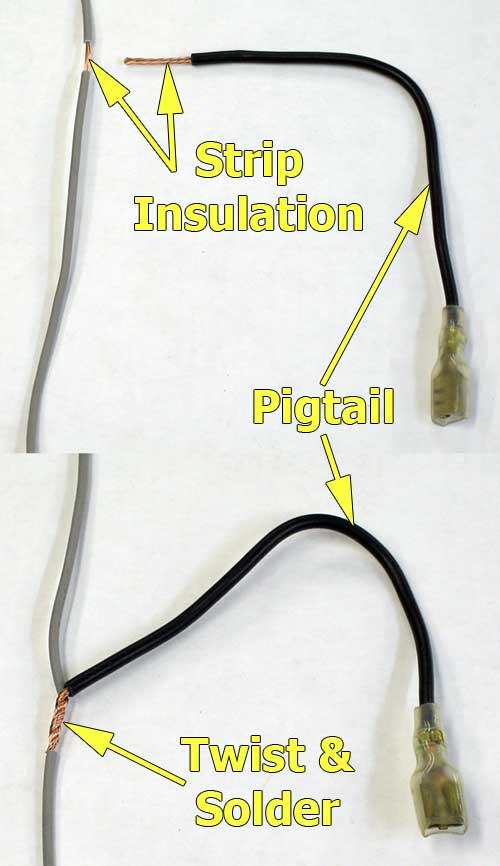
Also when I say splice, I mean a specific proper "splice". You never cut the wire you are splicing into, well if you want to do it right. So how you do it is you take a sharp loose blade, and you carefully strip the insulation around the wire off leaving the wire intact. you can do this by just going deep enough to cut the insulation and you do a circle around the wire on each side, and then you can peel the insulation off. Once you have an exposed portion of the wire with no insulation, what you do is you wrap the piece of wire you are splicing in around it (i.e. mechanical lock), then you solder it. once you are done, you can slide heatshrink over it by taking the pin out of the connector. You want a good connection on your coilpack power line.
I do the same type of splice for coils siting on cyl 2 and 4 into the "branch wire". when you splice in the new wires, make them point the direction you want before wrapping and soldering, and your wires will look so pro after heatshrink people will ask you to do theirs. for these you have to slide the heatshrink on in advance and dont let them sit too close while soldering or they will shrink on int he wrong spot (done that enough times lol).
If you had higher power demands, you could also use a relay off the battery terminal, and use the stock ignitor power wire to turn the relay on. I haven't heard anyone needing to do this, but for example 2jzgte's come with 2 EFI power lines for coils and injectors, the 2jzge just has one shared one. again never had an issue but if you did you just use a relay instead of tapping directly into the ignitors power wire, easy stuff.
Another worthy mention is if you are unwrapping your harness on th passenger side, you could pull back the coilpack wire from the stock coil into the valve cover area, and that could become your power "branch" wire and one of your 3 coil wires (for coil sitting on cylinder 6). not everyone unwraps the harness though but if you do it that way you already have a spliced in branch wire and one of the 3 coil wires which saves some time. I ran new wires of thicker gauge myself but this way should work also, that power wire is also spliced into the ignitor wiring, its just buried in the harness by the firewall somewhere.
Also, when doing all this sort of stuff, always use "stranded" wire with the lots of little strands, never use solid wires in a car or the engine bay, its a bad idea and also much harder to work with.
here is the closest image I could find about what I am saying, this is a textbook way of doing it, and I don't care what someones brothers cousins friend said was the best way to do it... I go by what my harda$$ EE professor taught me.
Last edited by Ali SC3; 07-14-16 at 03:58 PM.
07-14-16, 08:48 PM
#53
Thank you Ali for the last magic trick!!! I think I'm on the right track
I was looking at the picture of the stock igniter wires and if you look c1 c2 and c3 wires are exact same color wires that come off the coils black red tripe, green and black. The black and red stripe is on coil 1(cyl#2) the green wire went to the coil 2(cyl#4) and the solid black to coil 3(cyl6)
For right now I just twisted the wires together to make sure they are correct and then I'm going solder them properly!
Here is a pic of the original igniter with the original wiring pins in its locations.
Last edited by LEXXIUM; 07-14-16 at 09:17 PM.
07-14-16, 08:57 PM
#54
Sorry can't put 2 pics in one post on I phones.
Here is the shot of the original coil 1 cyl2 color coded black/red stripe wire, so the black and red wire I pinned to c2 on the igniter
If I'm not mistaken those 3 wires off coils go directly to the igniters on vvti models? So I just transfer to igniter same color same location?
I just do this little step by step for myself so others n/a-t guys can see it what they will do In the future and it's not all that hard yet
Last edited by LEXXIUM; 07-14-16 at 09:15 PM.
07-15-16, 10:26 AM
#57
looks right to me, but what I dont get is your first pic of the ignitor you had the wire color black/orange for b+ 12v and now its black/white for b+ 12V. toyota use both colors but not usually on the same car, looks fine though I am guessing on of those pics was someone elses?
07-15-16, 07:23 PM
#58
Yes, sorry I redid that, to this so I know what goes where, and I know I'm going to need to add 2 more wires to the igniter straight to the Jdm ecu per your diagram.
But the reason you see that, I was looking at the diagram #2 where I thought I saw that blue and white go in the pic too.
So right now I just did this so I don't forget, I just don't have much time this week
So the only 3 wires that leave out there are t1 2 and 3 which need to be hardwired
But the reason you see that, I was looking at the diagram #2 where I thought I saw that blue and white go in the pic too.
So right now I just did this so I don't forget, I just don't have much time this week
So the only 3 wires that leave out there are t1 2 and 3 which need to be hardwired