Camshaft position sensor error refuses to go away
#31
Driver School Candidate
Thread Starter
Join Date: Apr 2010
Location: Sweden
Posts: 21
Likes: 0
Received 0 Likes
on
0 Posts
So, there is no indication that this is not related to the VVT sensor.
Again, thank you for clearing that up for me.
#32
Driver School Candidate
Thread Starter
Join Date: Apr 2010
Location: Sweden
Posts: 21
Likes: 0
Received 0 Likes
on
0 Posts
I finally got some quality time with the multimeter today.
However, it was the other way around when I tested:
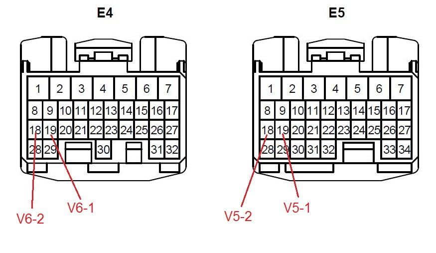
Continuity from E5-18 to V5-1
Continuity from E5-19 to V5-2

#33
Lexus Champion
When the camshafts rotate, the protrusion on the gear and the air gap on the pickup coil change, causing fluctuations in the magnetic field and generating an electromotive force in the pickup coil. As such, I believe polarity is important for these VVT sensors. If you're certain of the test results above, I'd suggest to correct the connections and see if it will resolve the DTC.
Last edited by rkw77080; 08-28-15 at 03:48 PM.
#34
Driver School Candidate
Thread Starter
Join Date: Apr 2010
Location: Sweden
Posts: 21
Likes: 0
Received 0 Likes
on
0 Posts
#35
Lexus Champion
According to the schematic, V5-1 (a red wire) should go to terminal 18, and V5-2 (a green wire) should go to terminal 19. These are indeed the connections you found on your car. Can you also confirm the wire colors?

Now I'm not sure which one to believe. If the wire colors match the schematic, then I would lean toward the schematic as the correct one - just my 2 cents worth.
Here are some other things we can do...

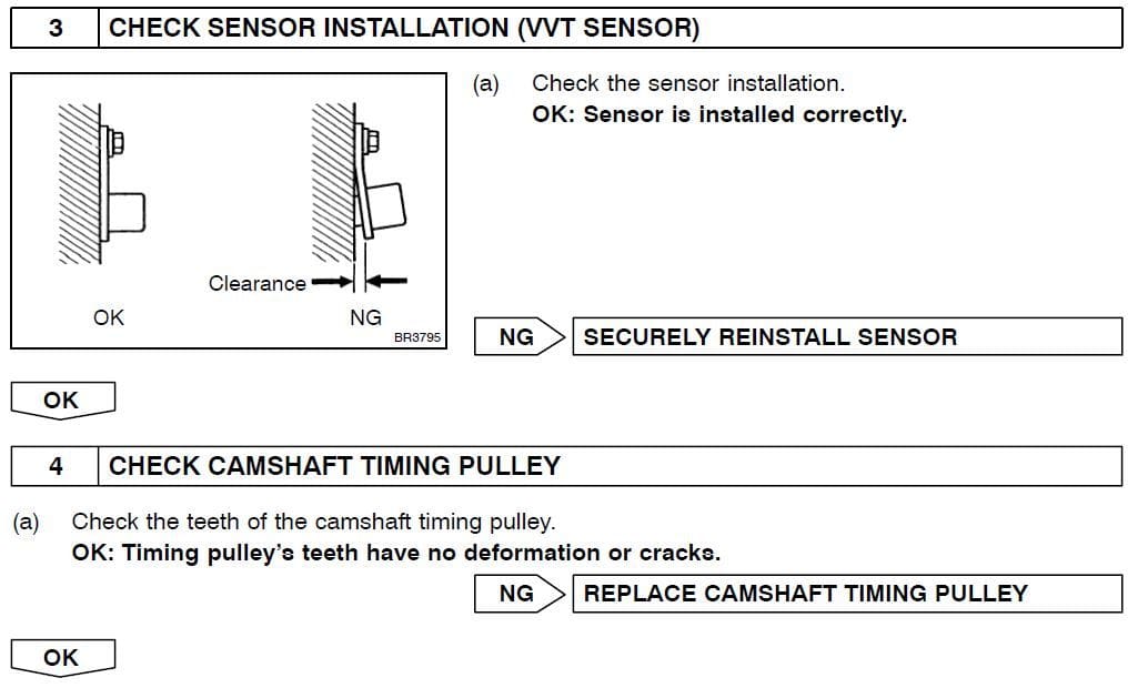
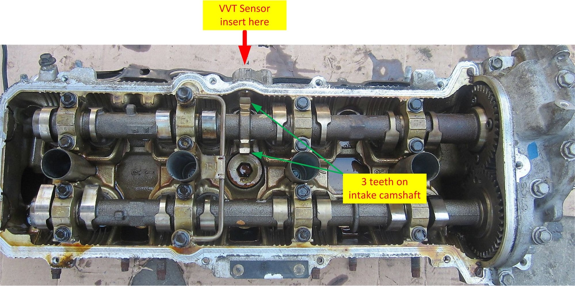
The 3 teeth (mentioned in Step 4) on the intake camshaft do not look as if they can be easily damaged (see photo below). So the remain problem (mentioned in Step 3) is that the VVT sensor was not seated properly. You may consider removing it and then re-seating it fully.

Last edited by rkw77080; 08-29-15 at 06:57 PM.
#36
Driver School Candidate
Thread Starter
Join Date: Apr 2010
Location: Sweden
Posts: 21
Likes: 0
Received 0 Likes
on
0 Posts
So I went back to the procedures in Post #20 and compare them with the electrical wiring schematic below. They are different! Post #20 shows E5-19 to V5-1 and E5-18 to V5-2.
According to the schematic, V5-1 (a red wire) should go to terminal 18, and V5-2 (a green wire) should go to terminal 19. These are indeed the connections you found on your car. Can you also confirm the wire colors?
According to the schematic, V5-1 (a red wire) should go to terminal 18, and V5-2 (a green wire) should go to terminal 19. These are indeed the connections you found on your car. Can you also confirm the wire colors?
#37
Lead Lap
Although it is extremely unlikely to have defective parts out of the box, have you tried testing the resistance of the VVT sensor when cold and hot? The procedure is given by section SF-85 in the manual and is shown on post #14 of this thread. Sensor should ohm out a 835-1400ohms when cold and 1060-1645 when hot. There is the odd chance you have an out-of-spec sensor. You can compare the one on bank 1 to the one on bank 2.
If this checks okay, plug the sub-harness into the sensor and check the resistance from the other end (at the ECU) just to make sure the resistance is similar. It is possible for the cable to be okay, the sensor to be okay, but the connection to be poor.
You can go on to check the voltage at the subharness just before the sensor with the battery on. This should rule out bum connections at the connectors.
If this still does yield any results, and the sensor is mounted correctly, then it may be the ECU. Unless rkw77080 has way to troubleshoot the ECU, then you may need to swap it out with another unit to test.
#38
Driver School Candidate
Thread Starter
Join Date: Apr 2010
Location: Sweden
Posts: 21
Likes: 0
Received 0 Likes
on
0 Posts
Update on this - sorry for the delay. A bad connection on the ECU side of the cable seems to be the best explanation I can think of.
When I tested things back in August, I followed the following procedure:
1. I started by taking off the connector on the sensor side, inspected that connection and that the sensor was properly installed. I put the connector back on and tried to start the car. It had starting difficulties.
2. I then took that connector off again, removed the ECU cover and checked continuity as described above. Since I had not discovered anything of interest, except what was probably an error in the service manual (see above), I reassembled everything and drove back into the garage. This time, it started perfectly, but the error lights were still on. Since the car quite often started without problems, I did not react to that.
Then, after a few weeks of infrequently driving the car, I noticed that it seemed to start OK every single time.
After a while, the VST light went off. The following day, the check engine light went off, too. Then, a week or so later, they came back.
Now, the check engine and VST lights come and go, but there are no starting difficulties.
Given that, my best guess is that the problem was a poor connection on the ECU side, and that was rectified by re-seating the connector after testing for continuity.
For now, I will just leave things as they are, in order not to wake up any ghosts, as I can live with those lights coming and going.
Thanks a lot, everyone, for helping with this.
Last edited by Helge; 12-05-15 at 11:55 PM.
#39
Driver School Candidate
Thread Starter
Join Date: Apr 2010
Location: Sweden
Posts: 21
Likes: 0
Received 0 Likes
on
0 Posts
So I lived with the check engine light and VSC malfunction light being mostly on, and sometimes off, for a few years. I tried putting some space age dielectric grease on the ECU connector to no avail, but made no other attempts at fixing it.
Some of the behaviors indicated that it was an electrical connection issue, e.g. driving long distances in rain seemed to help, and the error sometimes appeared after driving over speed bumps.
Other behaviors indicated that some part of the VVT-i systems was not working correctly, as the error often came back after turning off a warm engine and starting it. Also, perhaps the speed bump problem above was due to the acceleration after the speed bump and increased rpm and throttle opening.
Then the car did not pass an annual inspection due to VSC being disabled, so I figured I had to try something.
So I decided to replace the VVT-i control valve. It seemed to be the most common point of failure in the VVT-i system, and since it is easy to replace and can be had for less than $50 (genuine part on eBay), the downside was limited.
However, to be able to pull out the VVT-i valve, I had to move some cables, and when pulling the cables, I noticed that a gray connector below the VVT-i stuff on the radiator side of the engine was not properly clicked close. So I clicked the connector closed, put back the old VVT-i valve and reset the check engine light.
Problem solved. No more error P0340. Evidently, the mechanic had not fully closed the connector when replacing the VSV for ACIS (see above).
Last edited by Helge; 01-12-19 at 05:16 AM.
#40
Driver School Candidate
Thread Starter
Join Date: Apr 2010
Location: Sweden
Posts: 21
Likes: 0
Received 0 Likes
on
0 Posts
With P0340 gone for a few days, I have noticed that P1650 is back. It has come and gone twice.
The next problem to solve is whether
1. Replacing the VSV for ACIS never fixed the problem back in the day, and the P1650 error was always coming and going, but just wasn’t there on few the occasions when I read the codes. After all, the check engine light was on most of the time, or
2. The VSV for ACIS needs to be replaced again after less than 4000 km, which seems unlikely
The first thing I will check is the VSV for ACIS connector.

#42
With P0340 gone for a few days, I have noticed that P1650 is back. It has come and gone twice.
The next problem to solve is whether
1. Replacing the VSV for ACIS never fixed the problem back in the day, and the P1650 error was always coming and going, but just wasn’t there on few the occasions when I read the codes. After all, the check engine light was on most of the time, or
2. The VSV for ACIS needs to be replaced again after less than 4000 km, which seems unlikely
The first thing I will check is the VSV for ACIS connector.
The next problem to solve is whether
1. Replacing the VSV for ACIS never fixed the problem back in the day, and the P1650 error was always coming and going, but just wasn’t there on few the occasions when I read the codes. After all, the check engine light was on most of the time, or
2. The VSV for ACIS needs to be replaced again after less than 4000 km, which seems unlikely
The first thing I will check is the VSV for ACIS connector.

Thread
Thread Starter
Forum
Replies
Last Post


