When you click on links to various merchants on this site and make a purchase, this can result in this site earning a commission. Affiliate programs and affiliations include, but are not limited to, the eBay Partner Network.
hey guys, brand new poster here. I have an 07 IS 350, non-ML with Nav. i've been reading endless threads and posts on how to hack the inputs to splice in a video feed (dvd player, ps2, etc.) it seems you need 3 things:
hey guys, brand new poster here. I have an 07 IS 350, non-ML with Nav. i've been reading endless threads and posts on how to hack the inputs to splice in a video feed (dvd player, ps2, etc.) it seems you need 3 things:
as for the power of the dvd player or ps2.. im going to be using a power inverter.. you can either plug it in your cigarrette lighter and then plug in the ps2 power cord to it.. or if you want a hidden job you can splice the wire's of the power inverter and connect them to the back of the ciggarette lighter where the wires are.. and hide the inverter somewhere behind the dashboard/glove box.. and run the wires for the ps2 so its all hidden.
I know this is an old thread...but just wanted to make sure my wiring is right before I throw everything together. I bought a SPDT relay (pn# 275-0248) and a simple switch from radio shack. I have my proposed wiring diagram attached.
The orange wire is only tapped and from the tap, connected to the switch. Then another wire going from the switch to the relay. I realize the diagram may not be clear about that part.
Has anyone done this in a 2011-2013 newer model IS?
I took out my center dash to find that the wiring harnesses look different. so if anyone could help me out or point me in the right direction as to finding the correct wire for the camera input that would great!
I have a Lexus LS 430 (3rd Generation) 2001. Thinking about installing a backup camera to avoid hitting something. Can someone recommend a product. I do have a Navigation system; but, in the process of trying to update it myself as opposed to the dealer.
This is an update for anybody who has a newer second generation IS. I have a 2012 IS250 with navigation without ML. I have just successfully performed the rear camera hack with a switch, and will show you the right corresponding wires below. It is slightly different than previously described in this thread..
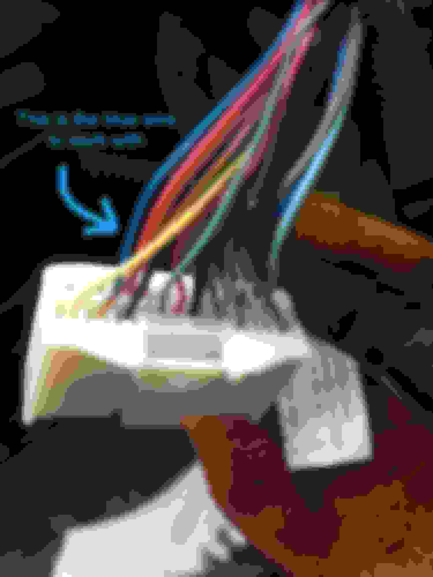
As mentioned before remove the head unit, and then isolate the J100(A) connector circled below. It's the big white connector on the lower right aspect of the head unit as you take it out. The one circled in Black is the correct connector to work with.
Now once you've isolated the connector, the blue wire on the farthest aspect to the right (left in the second pic) next to the red wire is pin number 16, which controls the feed from 12V going to the rear camera display.
This is the wire you must send a 12 V supply in order to display the rear camera.
I accomplished this by not cutting it but splicing into it and then placing a diode just before so the rearview camera still works well in reverse and doesn't put overload signal in the opposite direction. Find a 12 V connected to the ignition ( I tapped into the cig lighter since it's fused) and place a switch in between to control when the 12 V is sent to the blue wire. After this you are all done and it should work whenever you push the switch. There are no glitches and everything works and goes back to stock when the switch is off. I hope this helps
poorly drawn schematic I used:
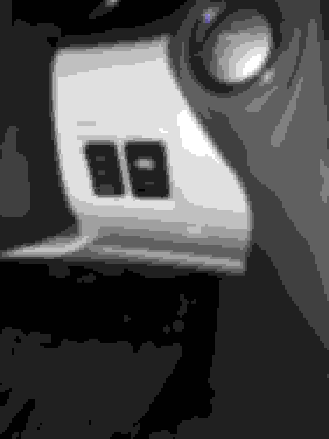
And the oem-like switch I used:
Edit I got the switch from eBay.
So I finally managed to do this hack today. Took the entire day but eventually I succeeded. The only difference from most others is that I was unable to find the reverse camera video signal behind the head unit so I resorted to leading wires all the way from the camera itself which was a real pain in the ***. Anyway... what I now have is a media player that can play videos on my Non ML with Nav head unit and a reverse camera when I put the car in reverse.
To achieve this I built an entire override circuit with 4 spdt relays which I mounted behind the head unit. I hope to post some pics tomorrow, but I can confirm that this hack does work.
I have a 2010 Lexus IS250 cabriolet so things where a lot more challenging than most... hehe. The parking guide lines do show up through any video displayed but you get used to it. What I have noticed is that when I open the cabriolet roof all guidelines dissappear and the words "guidance not available" displays at the bottom of the head unit display. If I can figure out how to emulate that somehow with a switch then things would be perfect, but I guess that's just a dream.. hehe.
I also own a 2015 Lexus RC350F Sport, but for that car I bought the beatsonic overide system which works like a charm so no hack was required for that car.
Hi, thank you for making these instructions so simple to follow. Im planning to get this done tomorrow, however I was not sure about which diode to use in this case? I went ahead and bought a variety of diodes and hope one will work? Thanks.
While performing the mods for Nav and installing VaisTech SLI iPod integration, I decided to work on the backup camera override that Airwolfe had described. As it turned out, this was a very simple mod. The "Blue" wire on pin 13 of connector J50 is the one to work with. This is immediately next to the well known and described "Pink" wire of the J50 connector fame.
To bore you with the details; J50 pin 13 "Blue" wire is the trigger which switches the Multi-Display to the camera mode. This is a +12v trigger, not the neg ground that has been mentioned here. This receives it's signal from JQ1 (which you really don't need to know).
To provide the override you must send a +12v signal to pin 13. The way I have accomplished this is by cutting the "Blue" wire. I re-routed this wire through a relay which in the NC (normally closed or non-energized) position the wire acts as though it was never cut and is as originally wired. Once the relay is energized, this wire is broken and the connector end is connected to a +12v source. This then tells the Multi-Display to switch to the rear camera. I used the +12v from the "Orange" wire on connector J50. It is from the Accessory circuit and therefore only energized when the ignition is on. This is seen in the schematic below.
Then I decided it would be nice to have an indicator LED to remind me that I am switched on to the modification. This was accomplished through the other side of the DPDT relay. To keep this simple I created a pdf schematic showing how I did this and with the part numbers for the relay and switch.
I then routed the switch to the left side of the steering column and used on of the "dummy" plugs adjacent to the shade switch. I have a photo of this. I will try to upload it if I can figure out how.
This worked beautifully the first time. It does not interfere with the navigation so there is no delay for "catch-up" when you turn the switch off. here was no need to interfere with the gray wire that Airwolfe had suggested as a possibile need. I belive that with a review of the schematic and this information, you will find this an easy modification. Now that I have done it, I'm just not sure why I need it.
I hope this helps and answers the questions that only testing as this can provide.
Any ideas if this would also work on an 08 LX570? I would love to use this while towing. I'll be adding the Grom vline2 in the coming weeks and would want to tackle at the same time.


 06-27-07, 12:59 AM