The Free Mod Series - Part VIII Cheaply Monitoring the ECU & A/F Ratios
 07-02-05, 06:55 PM
#1
Lexus Champion
Thread Starter

 There are soo many ways you can have fun with cheap electronics!
Reading and deciphering what your car is doing
Background:
So you're running stock, have some upgrades, or maybe even have a low power Turbo, or S/C system and you're still running the stock ECU. How can you possibly tune the engine without hundreds of dollars of expensive 1 time dyno tuning???
Theory
A tuned engine is a happy, powerful, and economic engine! The OEM doesn't understand this.
The Vf signal. Our lifeline into what the ECU is doing to the base fuel map!!!
The Vf signal is the ECU's way of letting the world know what it is deciding to do with the fuel mixture. When all the sensors have sensed, the ECU has picked a map to run in, and everything else is said and done, the Vf signal shows you what the ECU has decided to do. (This is your long and short term fuel trims in an OBD-I car)
By connecting any type of volt meter to the ECU/diagnostic port, you can read the votlage of the Vf signal.
0V = Rich mixture 11-20% from normal (ECU is leaning the mixture)
1.25V = Slightly rich mixture 4-10% from normal (ECU is leaning the mixture)
2.5V = Within 3% of the basic map
3.75V = Slightly lean mixture 4-10% from normal (ECU is richening the mixture)
5V = Lean mixture 11-20% from the mixture (ECU is richening the mixture)
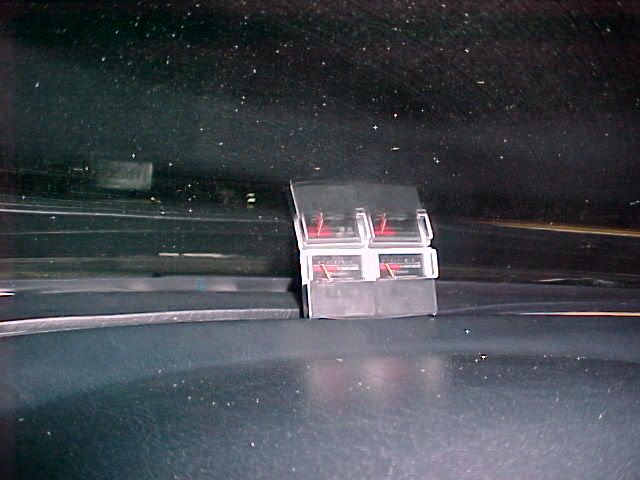
I have two wired up. One reading each Vf signal (Vf1, Vf2) One is for the front bank, while the other is for the rear bank. (Obviously I4's will have one Vf signal) If you feel like figuring out what the new voltages will be, you can bridge Vf1 and Vf2 and read the entire thing at the same time, but I wouldn't do it.
The o2 sensor. The only way to see the end result of the ECU's tuning!
The Vf signal shows you what the engine is doing in an attempt at perfect tuning. The o2 sensor shows you the end result o f what *actually* happened. By comparing the o2 voltage to the Vf voltage gives you a fairly accurate representation of what your engine is doing in the current conditions, and where you need to go.
This works with older lambda (narrow band) o2 sensors... You just can't accurately tell the A/F ratio.
If you can find an accurate volt/multi meter, capable of reading mV - you can wire those up to the oxygen sensor's themselves.
450mV should correspond with 14.7 air/fuel ratio. The ECU will try to achieve this basically any time you are not more than 80% throttle. The smaller the voltage, the leaner, the larger the voltage, the richer.
(bank 1 sensor 1 is the rear bank o2 sensor, bank 2 sensor 1 is the front bank o2 sensor)
The combination of the three allows you to see what the ECU originally wants to do with the A/F ratio, what the ECU is trying to do with the A/F ratio, and if it is successful in doing so. From that, if you have any idea about tuning you can interpolate fairly well how to do something.
Now! Someone will ask if it matters that you do both sets of signals. Not really, considering only the ECU itself can tune every individual signal. *However* I have all ready found that the signals do not always match each other... Often times during, and immediately after transition periods, the sensors will not match by a setting or two.
****************************************
There is one last trick you can perform with a heated lambda o2 sensor. Narrowband sensors are extremely inaccurate for several reasons, but the two biggest reasons CAN be delt with! Giving your run of the mill lambda o2 sensor the ability to fairly well extract the A/F ratio from the exhaust.
1) The LARGEST problem with reading a narrowband sensor is heat. The output on a lambda sensor will vary with heat as much as the oxygen content!!! Anyone that's ever watched one will know that they generally read all over the place... Stomp on the gas and they might immediately max out their signal. Let off and they'll stay there, then drop like a rock. (a classic example)
Solution
By placing a HEATED the lambda sensor (hego, heated narrowband, same thing) at the END of the exhaust - you just cut the wild 800*F sometimes up to 1000*F temperature swings down to a more manageable 150-300*F temperature swing.
2) There is a reason why Air / Fuel gauges suuuuuck. They're simply not ACCURATE enough to read a lambda sensor to begin with! Most of them read in 0.1v increments, and smooth & hold the signal so the gauge doesn't jump all over the place.
Solution
Forget tuning with an A/F gauge... Use a multi meter capable of reading mV. That's 0.01v. Most will read that.
A general guide would be:
.1 17:1
.2 16.5
.3 16:1
.4 15.4
.5 14.9
.6 14.4
.7 13.8
.8 13.2
.9 12.7
.985 12.1
As a side note... Many newer replacement lambda sensors will read from .1 to 1.1 volts. Some will even read from .1 to 1.3 volts! (allowing you to read richer A/F ratios).
There IS a built in safety net. Because lambda sensors are sensitive to heat, the more they heat up - the leaner the signal. They read falsely lean during the powerband between a 1/2 A/F ratio lean, that grows to around a 1.5 A/F ratio lean.
This is NOT a replacement for a wideband sensor on a forced induction, or n2o project... This is a project for N/A engines, or a very mild s/c, or turbo project.
CEL's are F'ing annoying
You can wire up a switch in your cabin to check, and clear CEL's!!! This is very easy to do since above the driver's left foot is a diagnostic port with second set of E1 and TE1 terminals. Simply splice the two wires together with a switch/hold button, and whenever you want to check/clear a code, simply hit the switch which will connect (ground) TE1 to E1!!! Instant basic diagnostic mode!!!
*****************************************
Part I Quicker Transmission Shifting
Part III Tuning the ECU
Part IV Cooling
Part V How to pick up MPG, and sleep with her too!
Part VI Acing Aerodynamics
Part VII Cheap Water Injection
Part VIII Cheaply Monitoring the ECU & A/F Ratios
*****************************************
Last edited by Pheonix; 07-02-05 at 08:03 PM.


Thread
Thread Starter
Forum
Replies
Last Post
New CL Vendor TTI Motorsport ECU re-flash for 3IS 8AR-FTS
TTITony
Club Lexus Vendor Product Announcements
0
03-24-17 09:26 AM