DIY: How to rebuild your SC rack & pinion. 20k pics (well alot)
 03-22-11, 06:29 PM
#1

today at work i am finally doing a 1st gen SC rack. its been a while since there is not a high demand for them. i just wanted to show you guys how it is done. i highly doubt anyone will try this.
TOOLS NEEDED
Rebuild Rack Seal kit (Kotek & Transtec) Transtec is double the price of Kotek, but they both do the job. i get fewer defects with transtec kit.
New rack boots
New inner tie rods
Grease
Monkey/Plumber wrench
Vise mounted to a sturdy table. ( do not attempt if you do not have this)
Various size punches (see pics)
2ft or so punch (see pics. also do not attempt if you dont have this)
Flat blade screw driver
Hammer
Channel lock pliers
6mm allen key
27mm socket
17mm socket
(other various sockets. see pics)
12mm wrench (tubing wrench preferred)
14mm wrench
Snap ring plier
Needle nose plier
LOTSSS OF RAGS
Bucket to catch old PS fluid.
Carb cleaner to clean your rack.
U-joint from your car to steer the rack. the one that is connected by 2* 12mm bolts (no pic)
1. mount your rack to the vise. take of the old boots (no pics) rack is super dirty. you can use carb cleaner to clean the rack. sometime the cleaner will take off the paint from the rack. it isnt a problem for me since i paint them after im done. i have a part washer tub to clean my racks. i use carb cleaner once in a while.
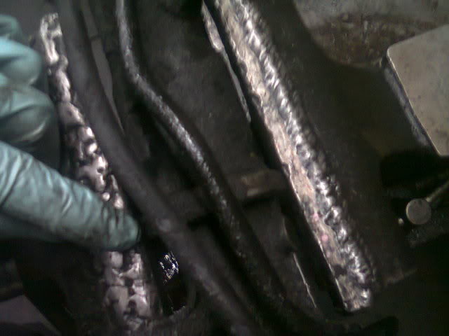
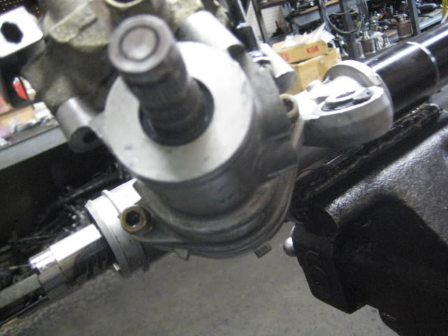
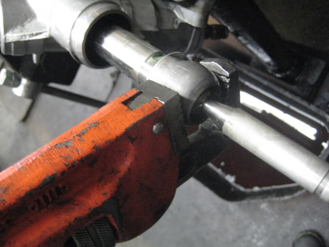
2. how it looks without the boot. take your flat blade and tap the lock washer at the folds (2 folds per tie rod)
3. take your monkey wrench and loosen the inner tie rod on both sides. make sure the rack in mounted tight to the vise. righty tighty lefty loosey
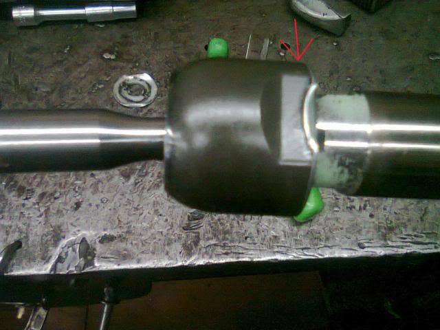
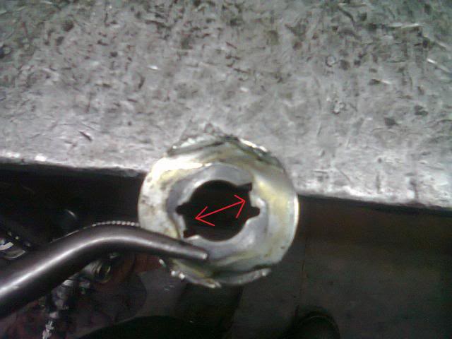
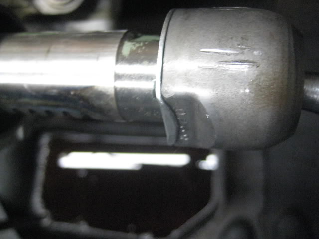
4. some times the kit wont come with new lock washers. dont worry you can reuse them. take the plier and use a hammer to flatten the washer. you can put the washer on the flat part of your vise. dont flatten the two small tabs. see ARROWS in pic
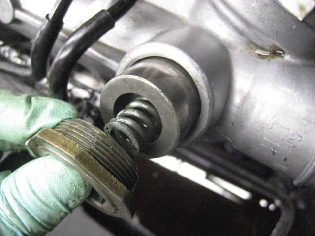
5. your rack should be clean by now. remount the rack on vise. loosen and remove the adjusting nut. you can use the monkey wrench to loosen the lock nut.
-remounted
-loosen lock nut w/ monkey wrench
-HOMEMADE tool i made, but not needed. 24mm nut welded to a rod. makes it easier but can use snap ring plier.
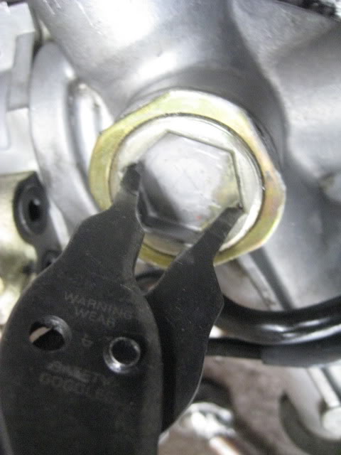
-this is what should come out and how it looks after.
6. Using the U-joint from your car. steer it the the right? and remove snap ring. (im using a HOMEMADE tool) careful when steering, there is PS fluid in the rack. place bucket to catch old fluids.
-showing my home made tool.

-snap ring is on the passenger side of the rack.
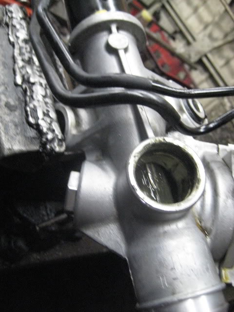
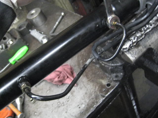
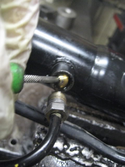
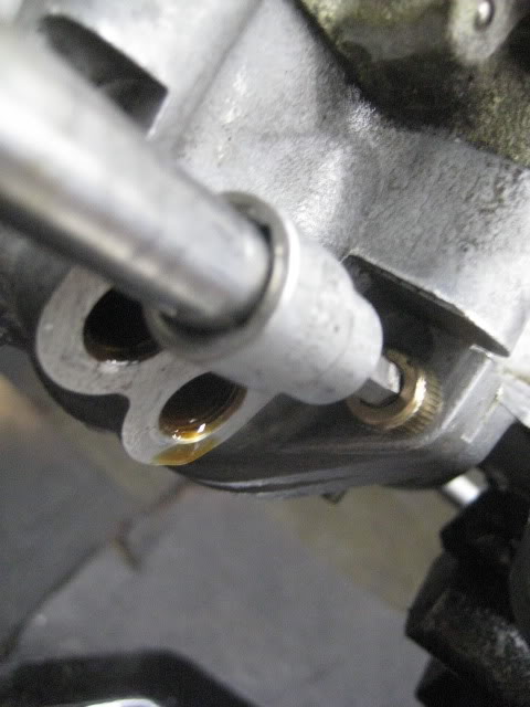
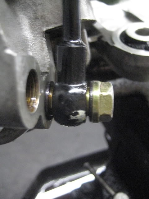
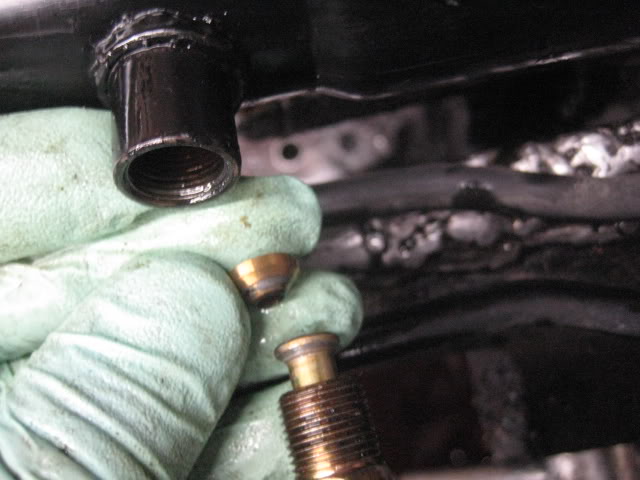
7. remove the 2* 14mm banjo. careful there is 2* washer per banjo bolt. 12mm wrench to remove the hard lines. i only remove one line and loosen the other since it isnt really needed to remove both, but you can if it gets in your way.
-banjos
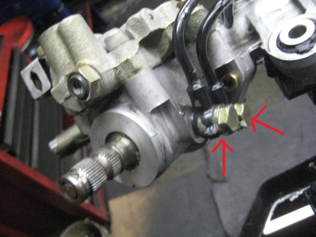
-the line with the wrench is the one i remove. the other i just loosen.
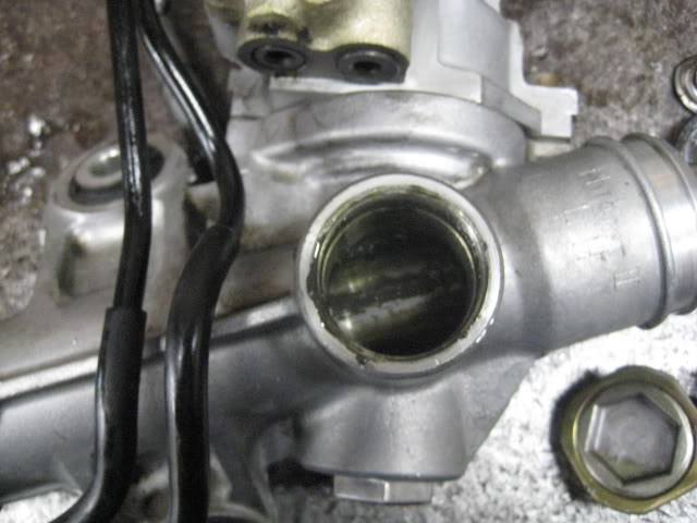
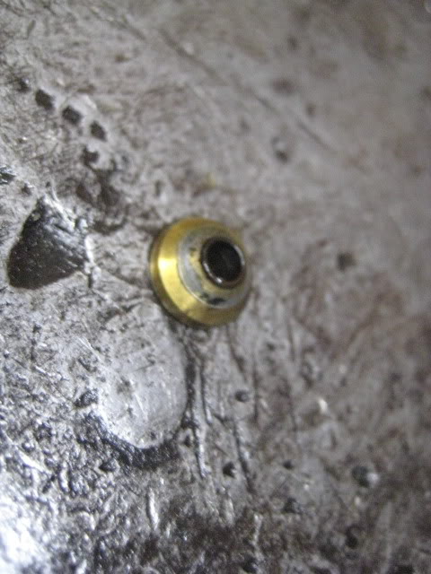
-fitting after line in removed.
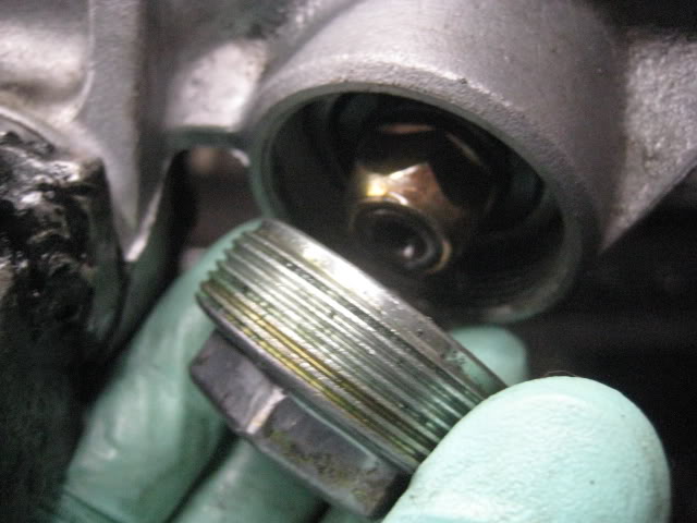
8. remove the 2* 6mm hex bolts with allen wrench. one on each side. remove the cover. the flat blade screw drive will help you pry it off.
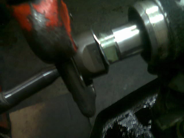
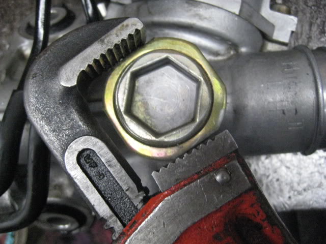
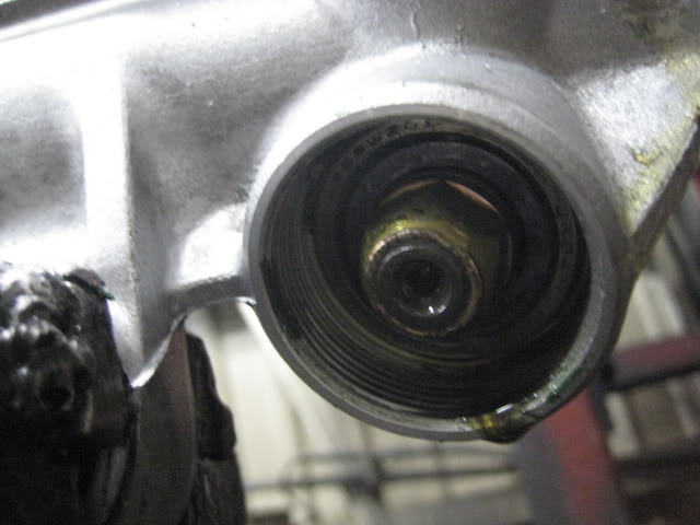
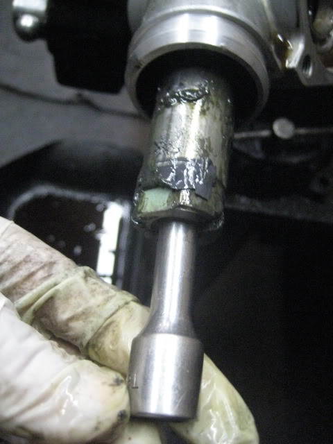
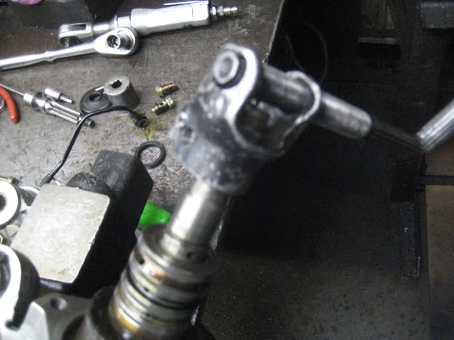
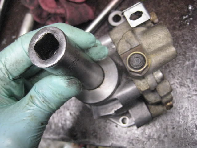
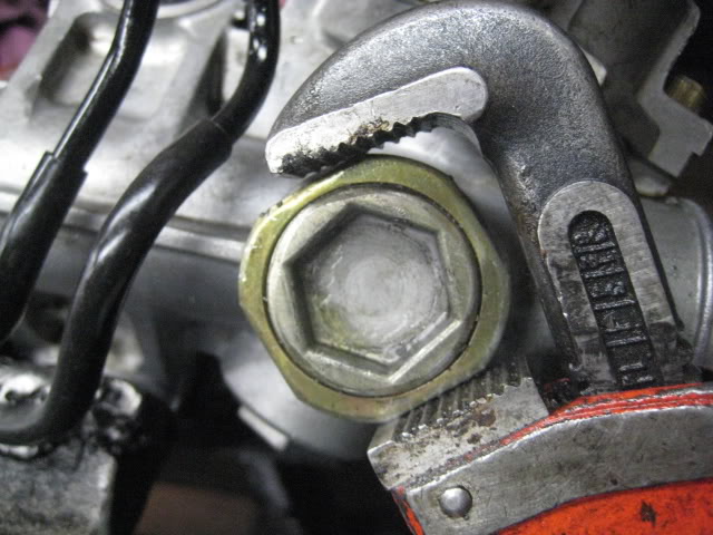
9. remove the 27mm nut and 17mm nut. when removing the 17mm the shaft will move. careful because old PS fluid will leak. keep turning the 17mm SLOWLY till the shaft locks and you should be able to loosen it.
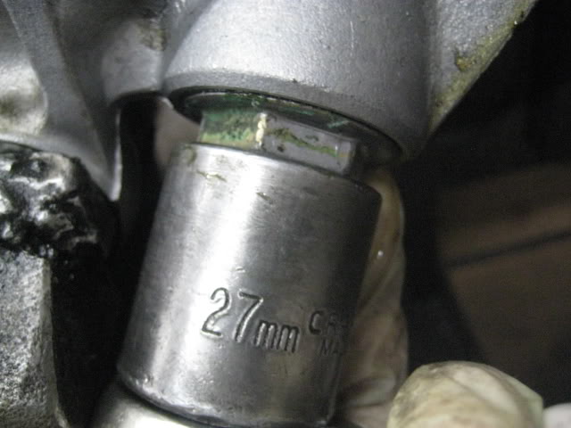
-after the 27mm is removed, the 17mm is exposed.
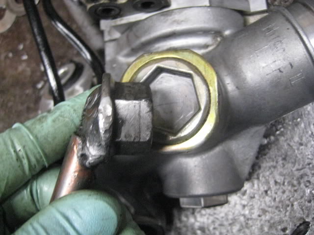
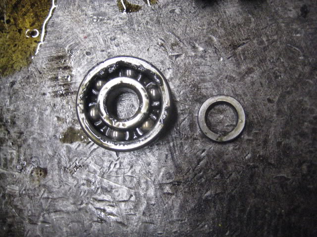
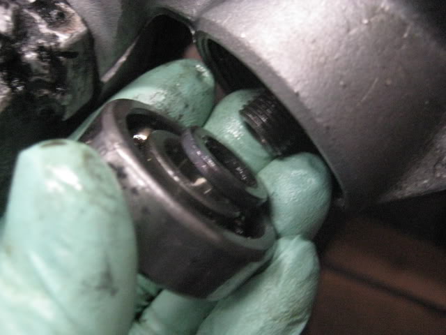
10. remove the steering valve. should come right out or use flat blade to help. remove the the washer and bearing after the valve. a quick tap with a ratch will take them out.
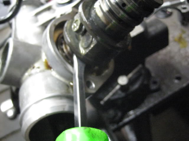
-washer and bearing inside
-them out
i am still adding. i just post so i dont hit the back button and have to redo everything.
TOOLS NEEDED
Rebuild Rack Seal kit (Kotek & Transtec) Transtec is double the price of Kotek, but they both do the job. i get fewer defects with transtec kit.
New rack boots
New inner tie rods
Grease
Monkey/Plumber wrench
Vise mounted to a sturdy table. ( do not attempt if you do not have this)
Various size punches (see pics)
2ft or so punch (see pics. also do not attempt if you dont have this)
Flat blade screw driver
Hammer
Channel lock pliers
6mm allen key
27mm socket
17mm socket
(other various sockets. see pics)
12mm wrench (tubing wrench preferred)
14mm wrench
Snap ring plier
Needle nose plier
LOTSSS OF RAGS
Bucket to catch old PS fluid.
Carb cleaner to clean your rack.
U-joint from your car to steer the rack. the one that is connected by 2* 12mm bolts (no pic)
1. mount your rack to the vise. take of the old boots (no pics) rack is super dirty. you can use carb cleaner to clean the rack. sometime the cleaner will take off the paint from the rack. it isnt a problem for me since i paint them after im done. i have a part washer tub to clean my racks. i use carb cleaner once in a while.
2. how it looks without the boot. take your flat blade and tap the lock washer at the folds (2 folds per tie rod)
3. take your monkey wrench and loosen the inner tie rod on both sides. make sure the rack in mounted tight to the vise. righty tighty lefty loosey
4. some times the kit wont come with new lock washers. dont worry you can reuse them. take the plier and use a hammer to flatten the washer. you can put the washer on the flat part of your vise. dont flatten the two small tabs. see ARROWS in pic
5. your rack should be clean by now. remount the rack on vise. loosen and remove the adjusting nut. you can use the monkey wrench to loosen the lock nut.
-remounted
-loosen lock nut w/ monkey wrench
-HOMEMADE tool i made, but not needed. 24mm nut welded to a rod. makes it easier but can use snap ring plier.
-this is what should come out and how it looks after.
6. Using the U-joint from your car. steer it the the right? and remove snap ring. (im using a HOMEMADE tool) careful when steering, there is PS fluid in the rack. place bucket to catch old fluids.
-showing my home made tool.
-snap ring is on the passenger side of the rack.
7. remove the 2* 14mm banjo. careful there is 2* washer per banjo bolt. 12mm wrench to remove the hard lines. i only remove one line and loosen the other since it isnt really needed to remove both, but you can if it gets in your way.
-banjos
-the line with the wrench is the one i remove. the other i just loosen.
-fitting after line in removed.
8. remove the 2* 6mm hex bolts with allen wrench. one on each side. remove the cover. the flat blade screw drive will help you pry it off.
9. remove the 27mm nut and 17mm nut. when removing the 17mm the shaft will move. careful because old PS fluid will leak. keep turning the 17mm SLOWLY till the shaft locks and you should be able to loosen it.
-after the 27mm is removed, the 17mm is exposed.
10. remove the steering valve. should come right out or use flat blade to help. remove the the washer and bearing after the valve. a quick tap with a ratch will take them out.
-washer and bearing inside
-them out
i am still adding. i just post so i dont hit the back button and have to redo everything.
Last edited by k7q; 03-23-11 at 08:47 PM.
 03-22-11, 06:51 PM
#2
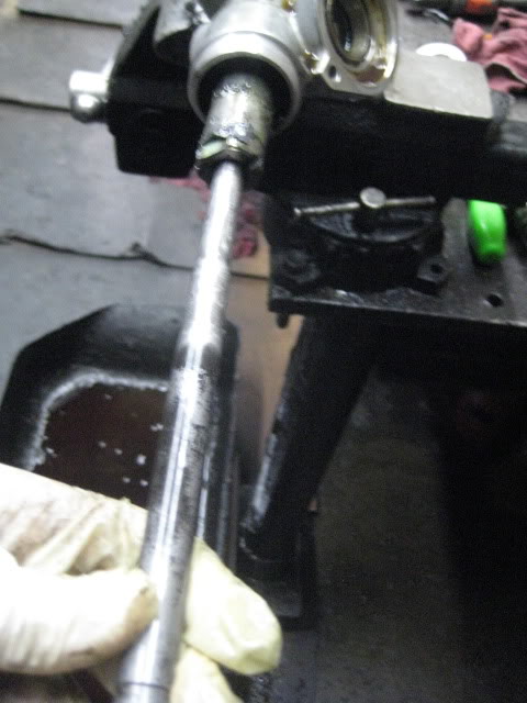
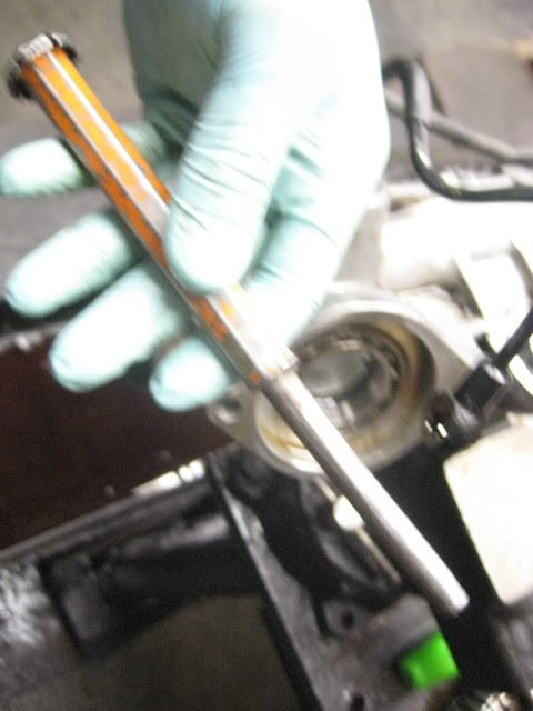
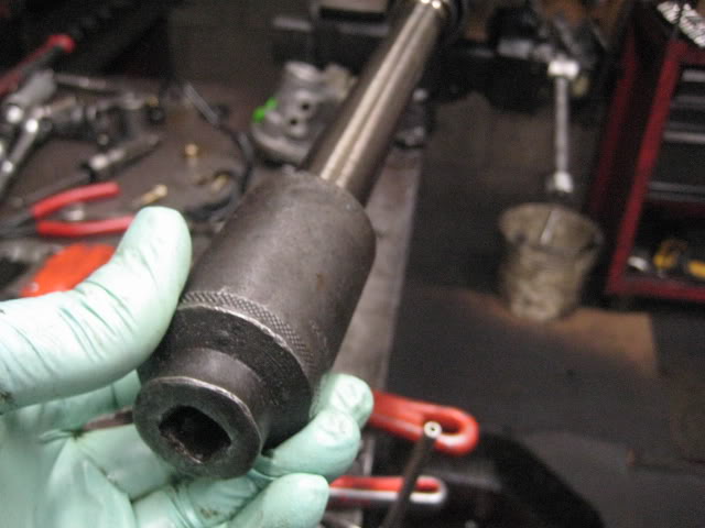
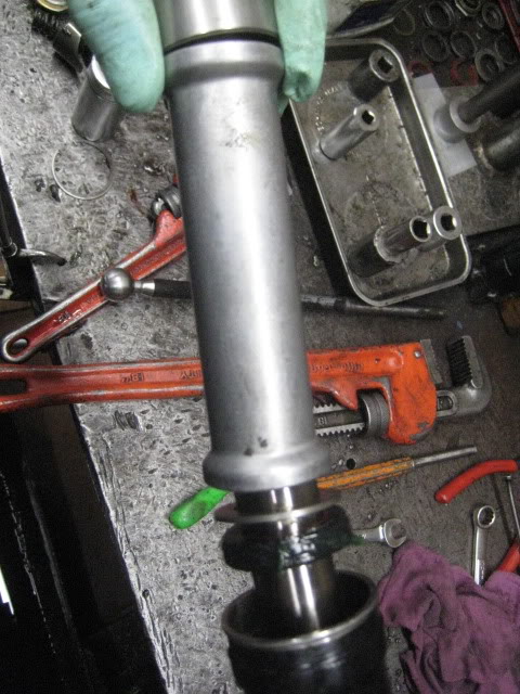
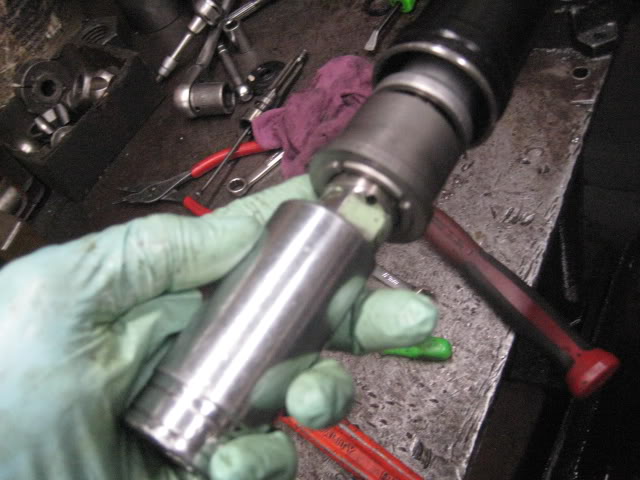
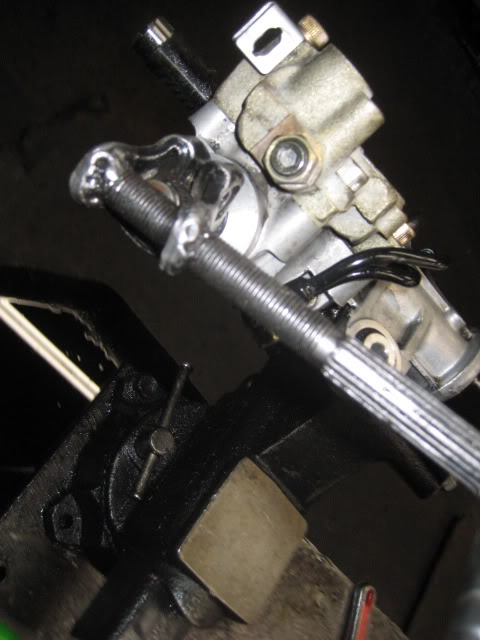
11. now to take out the shaft. a foot or longer 3/8 extention will work as a punch. since it fits inside where the tie rod goes and it wont damage the threads inside. i have a HOMEMADE punch i made. YES I LIKE THE WORD HOMEMADE INSTEAD OF CUSTOM. LOL
extention punch
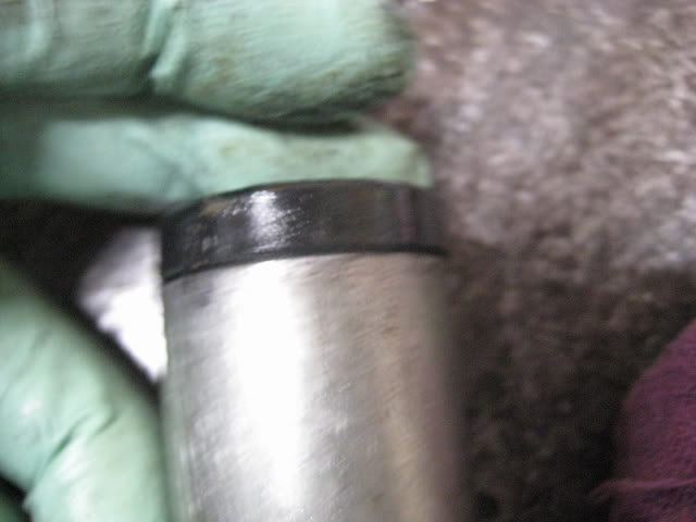
my homemade punch. careful when pushing the shaft out. PUSH SLOWLY. there is still old fluid inside the rack. once you feel the shaft stop get your hammer and give it a few good taps to pop the seal out.
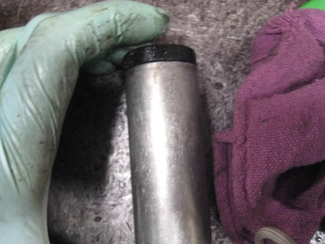
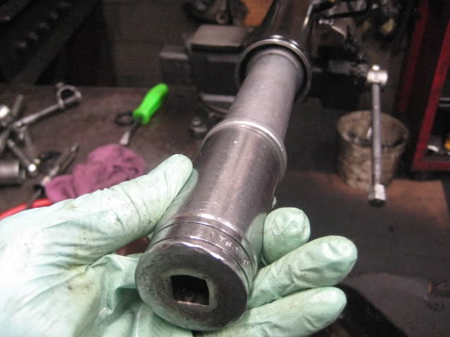
how it looks when the shaft is coming out.
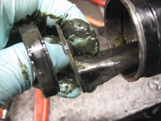
clean the gunk. carb cleaner works well.
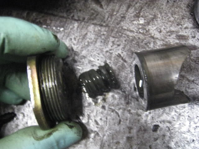
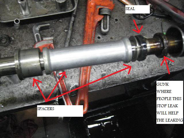
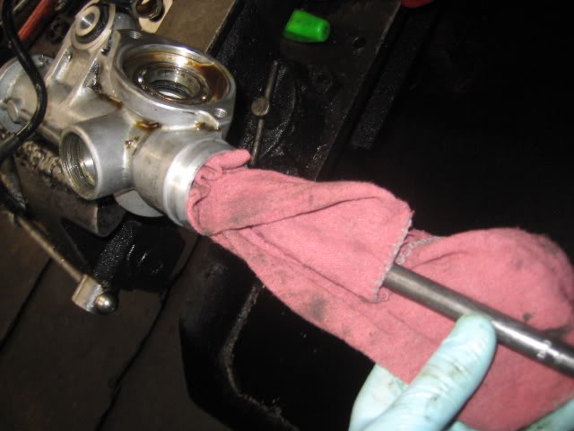
12. now you need to remove the other seal inside. you need a FLAT/BLUNT 2ft long punch. my punch just for taking these inner seals out.
place punch starting from driver side of the rack and give it a tap with the hammer. DO NOT HIT TOO HARD. you can break the spacer.
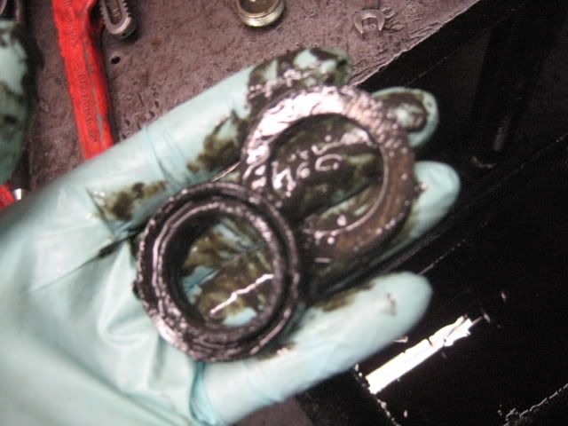
the inner seal and spacer out.
**NEW INFO. if you break the spacer dont worry. i found out newer racks dont even have these spacers. YES i tested this on a rack by removing the spacer and just installing the seal only.
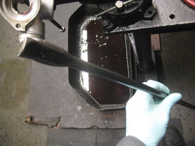
clean the inside of the rack. rag and punch does wonders. DO NOT CLEAN THE INSIDE OF THE RACK WITH CARB CLEANER. it will give you a hard time putting the seal back in. a good wipe is good enough.
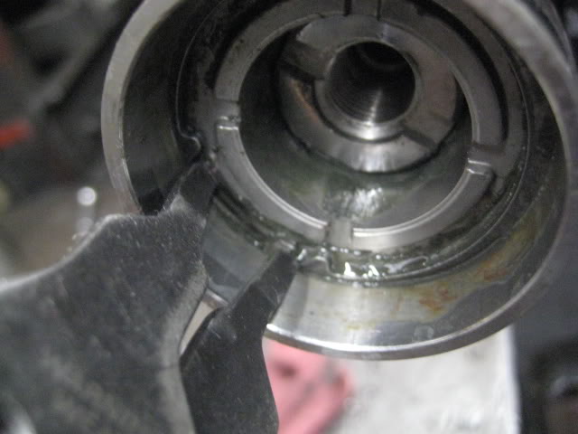
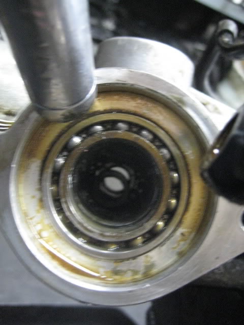
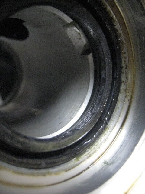
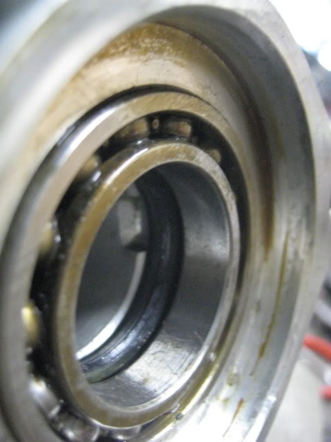
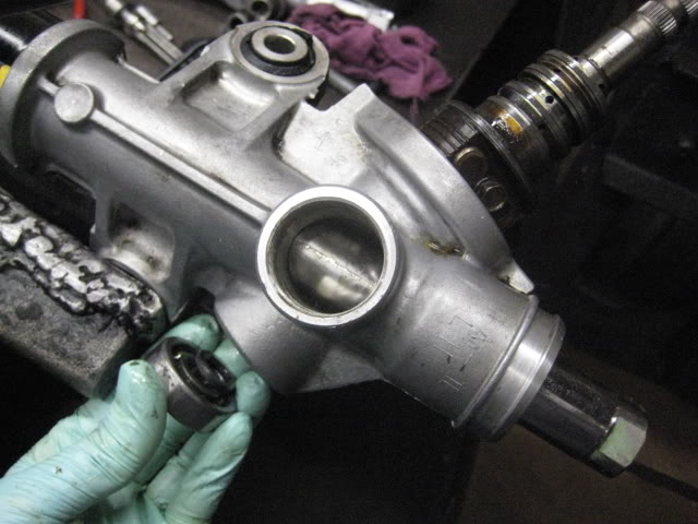
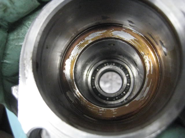
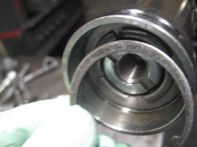
13. remove the bearing and seal where the steering valve once was.
my punch. a flat blade screw drive should work.
tap the bearing out from underneath. notice where i place the punch. tap all around the bearing not just in one spot.

after the bearing is out, you have to remove the seal. there is a grove in the rack so you can place your punch there. couple of tap with a hammer and it should come out
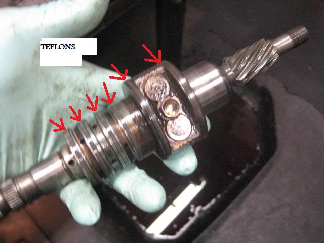
14. clean the steering valve and make sure all 6 TEFLONS isnt broken. very rare that they break. carb cleaner if needed.
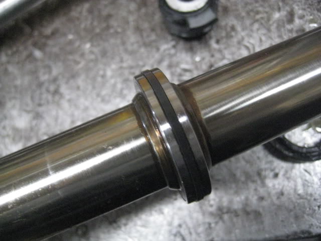
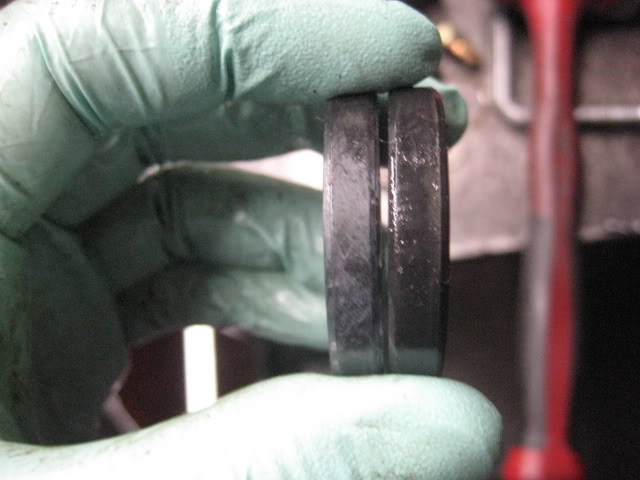
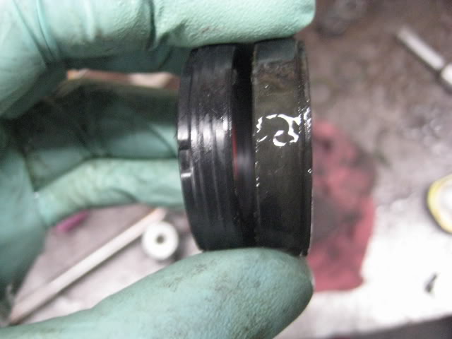
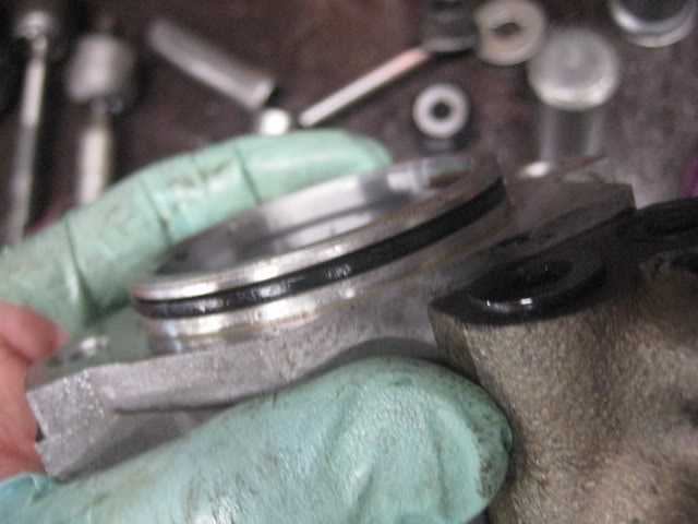
15. put the seal you just took out back in. ALWAYS COMPARE THE OLD AND NEW SEALS to make sure they are the same
new on left, old on right
put some grease around the new seal so it would be a bit easier to put back in. tap around the outer seal and NOT THE INNER PART OF THE SEAL.
(seal not all the way down)
to tap it all the way down you can place the OLD seal on top and tap the old seal. OR if you have a socket that is the same size of the outer edge of the seal, you can use the socket to help tap it down.
(old seal on top)
(NEW Seal all the way down.)
now put the bearing back on. tap all around the bearing not just in one place.
(bearing all the way down)
16. putting the inner seal on.
(comparing old and new)
i have this plastic film from a honda SEAL KIT to protect the seal from being cut by the teeth on the shaft. since you guys dont have this film and the kit doesnt provide one. you guys can put a long strip of tap on the edge of the teeth so it will protect the seal. put some grease on the inner and outer seal so it can slide easier.
remember to put the spacer back with the seal. remove film after the seal is pass the teeth.

putting into rack. it will be tight. dont pull it back out
you can use a 30mm socket to tap the shaft/seal back into place. it will be tight so give it some GOOD taps. you will know the seal is sit in place when the sound of the metal on metal tapping changes. careful it can mushroom easily.
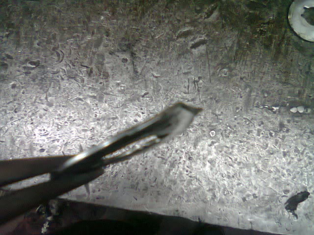
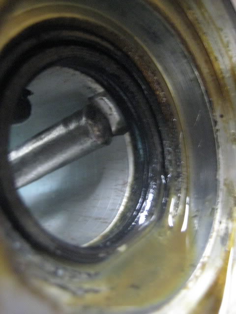
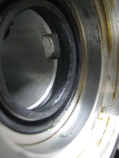
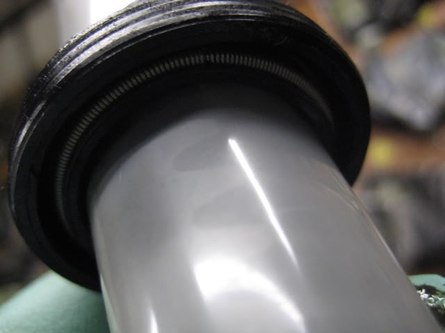
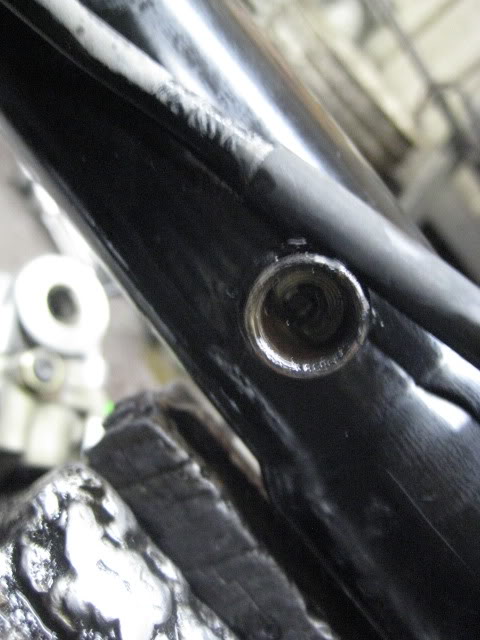
you can also know if the seal is in place by looking at where you took out the hardline. you should be able to see the black teflon and not the seal.
(not that great of a pic, but you can make out the teflon)
extention punch
my homemade punch. careful when pushing the shaft out. PUSH SLOWLY. there is still old fluid inside the rack. once you feel the shaft stop get your hammer and give it a few good taps to pop the seal out.
how it looks when the shaft is coming out.
clean the gunk. carb cleaner works well.
12. now you need to remove the other seal inside. you need a FLAT/BLUNT 2ft long punch. my punch just for taking these inner seals out.
place punch starting from driver side of the rack and give it a tap with the hammer. DO NOT HIT TOO HARD. you can break the spacer.
the inner seal and spacer out.
**NEW INFO. if you break the spacer dont worry. i found out newer racks dont even have these spacers. YES i tested this on a rack by removing the spacer and just installing the seal only.
clean the inside of the rack. rag and punch does wonders. DO NOT CLEAN THE INSIDE OF THE RACK WITH CARB CLEANER. it will give you a hard time putting the seal back in. a good wipe is good enough.
13. remove the bearing and seal where the steering valve once was.
my punch. a flat blade screw drive should work.
tap the bearing out from underneath. notice where i place the punch. tap all around the bearing not just in one spot.
after the bearing is out, you have to remove the seal. there is a grove in the rack so you can place your punch there. couple of tap with a hammer and it should come out
14. clean the steering valve and make sure all 6 TEFLONS isnt broken. very rare that they break. carb cleaner if needed.
15. put the seal you just took out back in. ALWAYS COMPARE THE OLD AND NEW SEALS to make sure they are the same
new on left, old on right
put some grease around the new seal so it would be a bit easier to put back in. tap around the outer seal and NOT THE INNER PART OF THE SEAL.
(seal not all the way down)
to tap it all the way down you can place the OLD seal on top and tap the old seal. OR if you have a socket that is the same size of the outer edge of the seal, you can use the socket to help tap it down.
(old seal on top)
(NEW Seal all the way down.)
now put the bearing back on. tap all around the bearing not just in one place.
(bearing all the way down)
16. putting the inner seal on.
(comparing old and new)
i have this plastic film from a honda SEAL KIT to protect the seal from being cut by the teeth on the shaft. since you guys dont have this film and the kit doesnt provide one. you guys can put a long strip of tap on the edge of the teeth so it will protect the seal. put some grease on the inner and outer seal so it can slide easier.
remember to put the spacer back with the seal. remove film after the seal is pass the teeth.
putting into rack. it will be tight. dont pull it back out
you can use a 30mm socket to tap the shaft/seal back into place. it will be tight so give it some GOOD taps. you will know the seal is sit in place when the sound of the metal on metal tapping changes. careful it can mushroom easily.
you can also know if the seal is in place by looking at where you took out the hardline. you should be able to see the black teflon and not the seal.
(not that great of a pic, but you can make out the teflon)
Last edited by k7q; 03-19-13 at 10:06 PM.
03-22-11, 06:56 PM
#3
17. now after the inner seal is seated properly. put the steering valve back on. adjust the shaft clockwise or counter so the valve can be put in place. put the bearing and washer back on. washer, bearing, then 17mm nut
DO NOT TIGHTEN THE 17MM YET. put the U-joint on the valve to hold it from turning and tighten the 17mm at the same time. if you try to tighten the 17mm the shaft will move and if it moves too far you the teeth can cut the inner seal you just put in and congrats your F***ED. buy a new rack. LOL
(my homemade tool holding the valve. use your U-joint.)the 17mm nut dont have to be super tight. just tight.
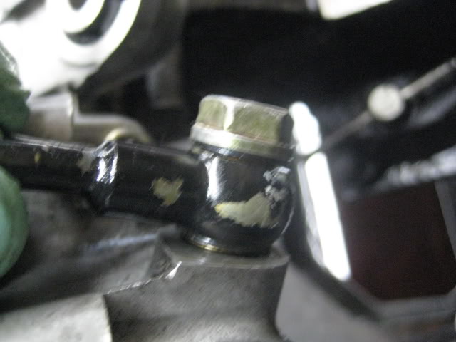
(how the 17mm nut looks after it is tighten) put the 27mm cap nut back on.
17. moving on to the valve housing seal. i use a 9/16 socket to take out the seal. 18mm socket should also work. sometime its kinda stuck, so it needs some good hits with a hammer. there is a bearing also. wipe housing with rag after the seal & bearing is out. i should have took a pic but forgot. time was against me. i was too slow rebuilding this rack and boss was like WTF are you doing taking pics. LOL
(place housing on FLAT surface. do not damage the lower part of the housing)
i have a perfect tool for placing the new seal in. a long 21mm should work. just compare the diameter of the new seal and socket before using it.
(pic of seal and my socket. just a BIT smaller then the seal perfect for putting the seal in place. (remember alwaysccompare old seal and new seal)
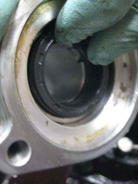
(seal and bearing in place)
NOW to the lower part of the housing the O-ring. just remove and find the new O-ring from your kit. compare the OLD and NEW so it's the same. put some grease on the new O-ring and put on housing.
(new O-ring greased and in place)
place housing over valve on the rack and put the 2* 6mm hex bolt and tighten them down EVENLY. if you tighten one first then the other, you might CUT the new O-ring and cause your rack to leak. then i will LOL
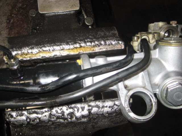
18. remember the hard line i only loosen? put the banjo bolt back on with the washers. this banjo goes on the lower part of the housing the other banjo on top (kit might not come with new washers, but i NEVER had a problem using the old crush washers)
put the hard line you removed back on. i start with the fitting end first. dont forget to put the fitting back also.
then this hard line banjo should be on top. you can see the old washers i use.
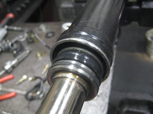
19. passenger side seal. put back in same order. the seal with the spring side slides in first. no pic, but if you have the seal you'll know what i mean.
(use the U-joint to steer the shaft left & right because of the LONG spacers)
im using a 1 1/8 socket to hit the seal in place. notice im didnt put one of the spacer on. grease the seal and give it a couple of taps and should slide in.
after the seal is in far enought for me to put the other spacer back on and steer shaft to correct place so the socket isnt hitting the shaft when tapping with hammer. now tap all the way till it stops.
place snap ring back on to lock.
20. put the adjusting nut back on. (notice the order) tighten the nut THEN loosen about 1/5 to 1/4 of a turn. then lock the nut in place with monkey wrench
use U-joint and steer the rack left and right. IT SHOULD NOT BE TIGHT. if it is tight loosen the nut a bit more.
21. back on the valve housing. remove the 3* 6mm hex bolts.
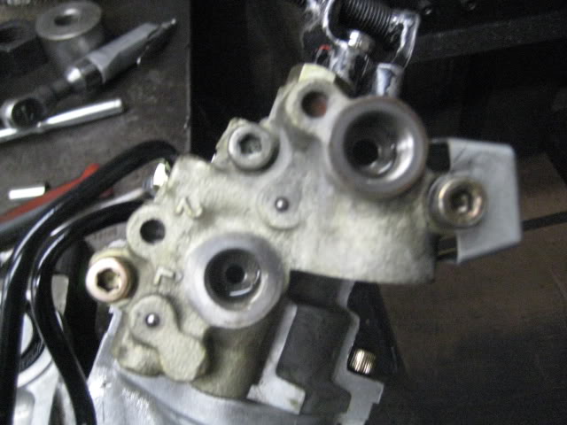
looks like this after removed
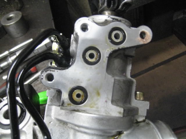
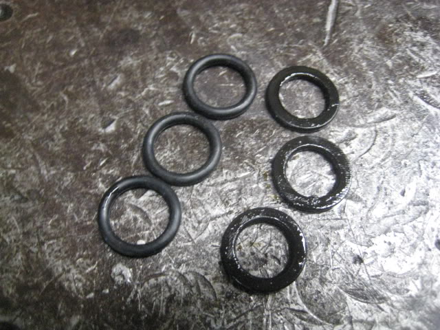
replace the 3 O-rings with new ones and tighten the valve back in place.
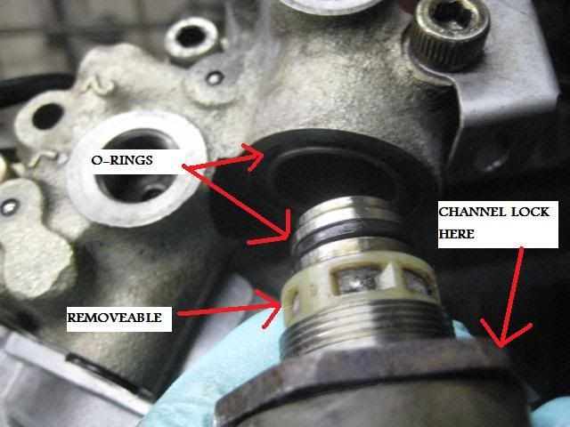
22. the sensor on the rack. i dont supply the sensor when i sell the rack. you should be able to use a channel lock pliers to romove the sensor. CLEAN THE SCREEN it will be dirty. the screen is also removeable for easier cleaning. also replace the 2* O-rings.
DO NOT TIGHTEN THE 17MM YET. put the U-joint on the valve to hold it from turning and tighten the 17mm at the same time. if you try to tighten the 17mm the shaft will move and if it moves too far you the teeth can cut the inner seal you just put in and congrats your F***ED. buy a new rack. LOL
(my homemade tool holding the valve. use your U-joint.)the 17mm nut dont have to be super tight. just tight.
(how the 17mm nut looks after it is tighten) put the 27mm cap nut back on.
17. moving on to the valve housing seal. i use a 9/16 socket to take out the seal. 18mm socket should also work. sometime its kinda stuck, so it needs some good hits with a hammer. there is a bearing also. wipe housing with rag after the seal & bearing is out. i should have took a pic but forgot. time was against me. i was too slow rebuilding this rack and boss was like WTF are you doing taking pics. LOL
(place housing on FLAT surface. do not damage the lower part of the housing)
i have a perfect tool for placing the new seal in. a long 21mm should work. just compare the diameter of the new seal and socket before using it.
(pic of seal and my socket. just a BIT smaller then the seal perfect for putting the seal in place. (remember alwaysccompare old seal and new seal)
(seal and bearing in place)
NOW to the lower part of the housing the O-ring. just remove and find the new O-ring from your kit. compare the OLD and NEW so it's the same. put some grease on the new O-ring and put on housing.
(new O-ring greased and in place)
place housing over valve on the rack and put the 2* 6mm hex bolt and tighten them down EVENLY. if you tighten one first then the other, you might CUT the new O-ring and cause your rack to leak. then i will LOL
18. remember the hard line i only loosen? put the banjo bolt back on with the washers. this banjo goes on the lower part of the housing the other banjo on top (kit might not come with new washers, but i NEVER had a problem using the old crush washers)
put the hard line you removed back on. i start with the fitting end first. dont forget to put the fitting back also.
then this hard line banjo should be on top. you can see the old washers i use.
19. passenger side seal. put back in same order. the seal with the spring side slides in first. no pic, but if you have the seal you'll know what i mean.
(use the U-joint to steer the shaft left & right because of the LONG spacers)
im using a 1 1/8 socket to hit the seal in place. notice im didnt put one of the spacer on. grease the seal and give it a couple of taps and should slide in.
after the seal is in far enought for me to put the other spacer back on and steer shaft to correct place so the socket isnt hitting the shaft when tapping with hammer. now tap all the way till it stops.
place snap ring back on to lock.
20. put the adjusting nut back on. (notice the order) tighten the nut THEN loosen about 1/5 to 1/4 of a turn. then lock the nut in place with monkey wrench
use U-joint and steer the rack left and right. IT SHOULD NOT BE TIGHT. if it is tight loosen the nut a bit more.
21. back on the valve housing. remove the 3* 6mm hex bolts.
looks like this after removed
replace the 3 O-rings with new ones and tighten the valve back in place.
22. the sensor on the rack. i dont supply the sensor when i sell the rack. you should be able to use a channel lock pliers to romove the sensor. CLEAN THE SCREEN it will be dirty. the screen is also removeable for easier cleaning. also replace the 2* O-rings.
Last edited by k7q; 03-23-11 at 08:44 PM.
The following users liked this post:
RamAirRckt (07-17-17)
03-22-11, 06:57 PM
#4
23. putting the inner tie rods back on. i have a press to press the OEM tie rod. i dont like the aftermarket replacement because their metal is softer then OEM. i use aftermarket replacement when the OEM tie rod is beyond repairable.
REPOSITION THE RACK ON THE VISE. make sure the rack is on tight before tighten the tie rods.
(lock washer then tie rod) you can put lock-tight on the threads if you wish.
once tight, use the hammer to bend the lock washer.
do to both tie rods
NO PICTURES FOR THIS PART since i test my racks before selling them.
put grease on the teeth of the shaft. use U-joint and steer left and right so the grease is spread out in the rack. do this for about 3-4 times. more grease wouldnt hurt. just messy. only grease the side with the teeth not the other side where it is smooth also put grease on the inner tie rods then put your new rack boots on and reinstall to car.
questions? LET ME KNOW.
GOOD LUCK YOUR GOING TO NEED IT
Last edited by k7q; 03-23-11 at 08:49 PM.

Trending Topics


 03-28-11, 09:43 PM
#13
it mean i hope you guys did everything right because you guys dont have a machine to test it. only way you guys can test it is by installing back into car and hopefully it doesnt leak.
takes me about 30-45 mins to rebuild a rack. depends on what rack it is. only time consuming part is cleaning the rack.
Last edited by k7q; 03-28-11 at 09:47 PM.
