When you click on links to various merchants on this site and make a purchase, this can result in this site earning a commission. Affiliate programs and affiliations include, but are not limited to, the eBay Partner Network.
I got a great deal on this ATI Procharger.
With the 2.8" pulley and 3.05 step up ratio it came with:
At 550 rpm engine idle, the procharger will spin at 3,470 rpm.
When cruising the engine is usually around 2,000 to 2,500 rpm, so the procharger will spin at 12,620 to 15,775 rpm.
At 6,200 rpm redline, it will spin at 39,122 rpm which is still 20,878 less than it's max spin rate (60K) which seems like a good margin. These numbers are about what the RMM kits spun at, at a solid 6-7 PSI
I have a list of everything I need to buy and build, it will be pretty straight forward. I really like one-off projects.
Because of my transmission cooler, I will not be doing a front mount intercooler.
I'll be using a factory OEM side mount intercooler for the 1998-2005 (JZ161 body not earlier JZ147) JDM Aristos which is a direct bolt on.
The multiple brackets pictured are thin aluminum, but purely for prototyping and measurement reasons. Don't laugh!
The final bracket will be steel, one piece, with nicer curves. Maybe CNC cut/powder coated black at some point.
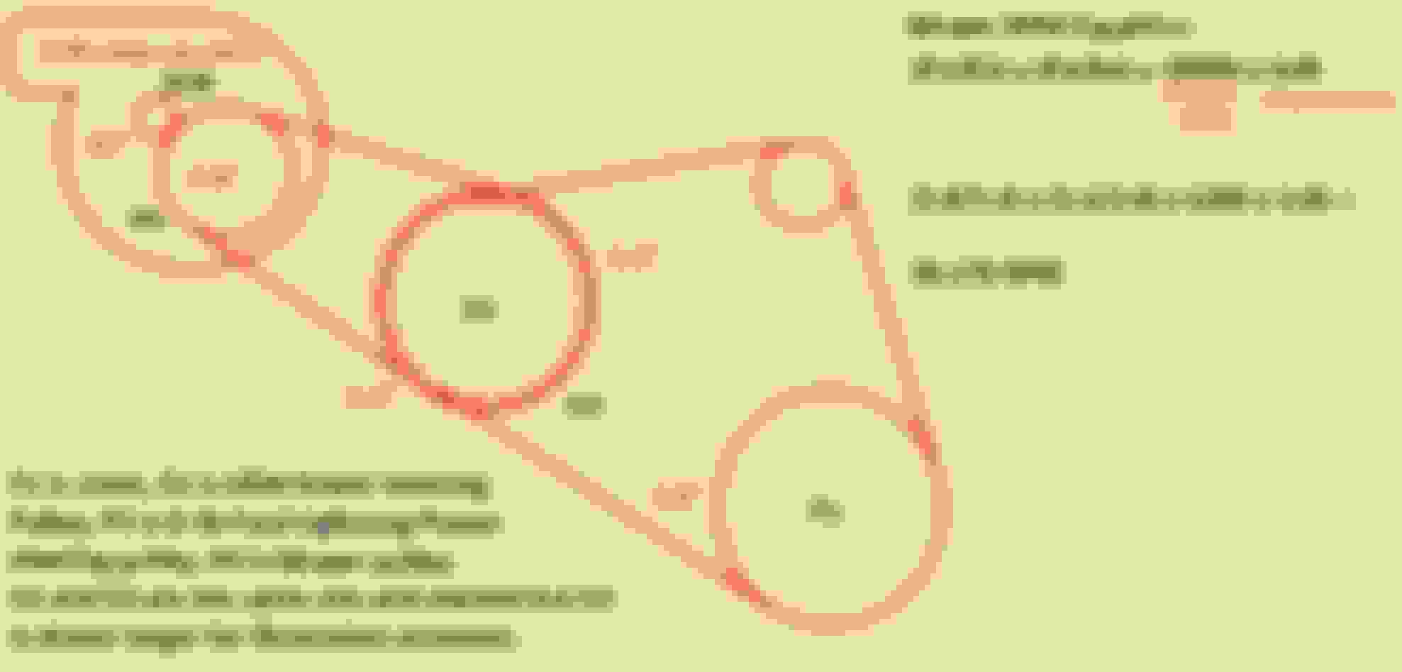
A metal ribbed pulley welded onto the power steering pulley will drive the ~28" belt to the procharger pulley
A small tensioner pulley will be mounted to the bracket to provide tension to the belt
I think it will end up being around 340 to 370 wheel horse power, so 430 to 460 HP crank at 20% drive train loss.
Because of the car's weight which is around 3800lbs, and all my mods, it will probably behave more like a 4,300lb car with 490+ horsepower.
All that and numbers aside, I know the 0-60 and 1/4 mile times will go down and acceleration will be even better, so in that I'll be happy.
Here is a diagram below of how it will be on the car (the charge pipe will be routed different, was drawn for illustrative purposes)
I have another thread that was an NA build, with all possible bolt-ons and transmission mods.
The cold pipe with the MAF flange to the throttle body is actually routed underneath and runs up between the fan shroud and engine.
I have an official parts list and will constantly update this with a date at the bottom.
I have fit them on my car, measured, and looked at OEM parts and custom parts at my work and confirmed they will work.
Hardware:
Procharger Headunit Housing Mounting Bolts for Bracket: 5/16 x 18 (coarse thread) x 3/4” length (x4)
Extended Cam Cover Bolt (Upper) for Bracket: M6 x 1.0 thread 2” length (x1 or x2)
Extended Cam Cover Bolt (Lower Right) for Bracket: M6 x 1.0 thread 4" length
Spacer for Lower Cam Cover Bolt to Bracket 3" length
Long 5/16 x 18 (coarse thread) 4" length (x1) and 3" length (x1) (bolts for the procharger belt tensioner assembly fitted to the custom bracket)
5/16 x 18 nut/coupler nut (x2) (welded to the supercharger bracket to thread the other tensioner assembly bolt)
OEM bolt from stock air box resonator mounting spot on valve cover closest to the front of the car M6 x 1.0 thread 1" length? (x1)
Extended Water Inlet Studs: M8 x 1.25 thread - 3.25" length (actually 90mm bolts with heads cut off)
OEM Intercooler to Frame Mounting Bolts: M6 x 1.0 thread 2" length (x3)
-4AN female fitting for oil send on headunit (straight) (x2)
-8AN female fitting for oil drain on headunit (right angle) (x2)
3 feet of -8AN hose size
5 feet of -4AN hose size
T fitting with 1/8" (x28 thread) BSPT female, 1/8" (x28 thread) BSPT male, with 1/8" (x27 thread) NPT female for intercepting oil at pressure switch to send to headunit (eBay seller p2p0 item number 132046408027)
-4AN to 1/8" NPT fitting for T fitting to oil send hose (driftmotion part DM3040)
-8AN aluminum weld bung for oil level switch block off plate for oil return (driftmotion part DM3409)
Main Items:
P600B ATI Procharger Headunit
Cheap Wideband Gauge Kit with O2 sensor (not permanent install, just for tuning)
Cheap boost gauge (not permanent install, just for tuning)
2001 Hyundai Sonata/Santa Fe 2.7L V6 Belt Tensioner Assembly
2001 Ford Lightning Smooth Idler Pulley (mounted in place of stock 6 rib sized Hyundai pulley on the hyundai tensioner assembly)
2001 Ford Lightning 8-rib Power Steering Pulley (center drilled out to 1" and welded to p/s pump pulley with pipe spacer)
2004-2009 Mazda RX8 (Manual) Denso 430cc Yellow Injectors.
-MAF Sensor Flange on Cold side of Pipe (aluminum flange section from cheap eba 1998-2000 GS300 CAI kits)
Aristo JZ161 (2nd Gen) OEM Side Mount Intercooler
3" ebay Aluminum Inter cooler Piping kit
Silcone couplers:
3" to 3.75" for air filter to procharger intake.
3" to 3" (included in kit) from procharger outlet to 3" hot pipe start (s-shaped)
3" to 2.5" for hot pipe end to enter SMIC intake
2.5" to 3" for the SMIC outlet to 3" cold pipe start
3.25" to 3" for cold pipe end into throttle body
Steel Bracket for Procharger
2.5" OD stainless steel pipe cut 1.75" long. (Fits in the back valley of the Ford pulley with good welding spots)
3x Thermostat Housing/Outlets (cut for just the flanges, to space out lower radiator hose to clear supercharger belt)
300K8 Sized Belt (30” belt length x 8 ribs)
Pod Air Filter/Pipe with 3 OEM breather/vacuum fittings attached
RKS Supercharger Bypass Valve (also need ~1.5 aluminum pipe 2x quantity about 2" each)
Braided Lines/Fittings for Oil Send/Return 4-5ft length (x2)
Power Steering Bracket/Different size Hoses (x2) (3/8"?)
1" diameter aluminum pipe cut to about 2.5" long (2x quantity) (one pipe welded to intake air filter pipe, and other welded to cold charge pipe for diverter/bypass valve hose attachments)
1/4" inner diameter aluminum pipe about 1" long (2x quantity) (for OEM vacuum fittings/PVC valve on the air intake pipe)
I definitely don't underestimate the belt tension and engine torque.
Those brackets were really just for fitting the thing as I couldn't hold it, check alignment, etc.
Aluminum is also easy to drill, cut, and bend.
The hood closes fine, and where it is pictured is the final actual location it will spin at. The headunit-to-fender panel bracket will be drilled into the fender. Discarded idea.
I've included a picture that will show how the CNC/powdercoated bracket will look.
The steel one I'm building now and seen on the car next wont be as curvy, but the same basic shape and just as strong.
It will also have less of a Z shape, and more right angular. That was a part of the fitting process.
It utilizes x7 bolts holding it in as included in the hardware list. x4 head unit bolts, x2 cam cover bolts, and x1 cam housing bolt.
Thanks Plex! I have to say your Supra looks amazing. The TT is my favorite Japanese car of all time, in which is probably in my top 3 cars. Having a FI 2JZ and 1UZ would be really cool.
Kitabel, you are completely right. The bracket did help me hold it up for fitment, but there will be too much pressure on it when the engine rotates so that will have to be discarded.
Actually, there is a bolt on the valve cover that was used to mount the stock ait intake resonator.
It is hard to capture in a photo, but it aligns pretty well horizontally with the lower headunit bolt hole.
It's bracket will go from there towards the back of the car, behind the headunit, and mount on this valve cover bolt providing torsional rigidity.
This combined with the rigidity of the bracket legs going in front of the headunit, will be very strong.
Here is a mock-up of where I will move the power steering reservoir as well.
If you can run a bracket to something like the bolt holes for the intake resonator that I know you no longer have, that'll be ideal. The more 3D you can make that bracket, the stronger it'll be.
Thanks for the idea!! I almost forgot about those bolt holes because I cut those stock bolts in half and put them back in to look OEM.
That might be a good option.
The final version might have something like this pictured below to add a lot of strength. The light red lines go under the unit.
The thickness of steel I'm using will have no flexing, and combined with the multiple mounting points, I know it'll be very rigid.
Again I will run it off the belt with the stock intake hooked up to the side, just to make sure it doesn't flex.
It will sad yet awesome to hear the whine/turbine type sound without it being plumbed to the intake but from there it will be close to finishing.
Thanks, I'm trying to share as much info as I can.
I think for any one attempting to do this, most of it is research, trial & error, fitment, etc. but really rewarding once done right.
I've tackled how I will move the lower radiator hose to clear the ~35" 8 rib supercharger pulley belt.
I am buying 3 water outlets (although they are technically inlets) and sawing the tube/round part off, with just the flange section remaining.
They will be stacked, hence moving the hose out towards the front of the car.
Alot of supercharger kits included a single spacer, but this will work the same, with RTV in between each once. They will have to be cut really flat.
I will have to remove the x3 stock studs that hold the current inlet on, and buy x3 longer bolts, cut the heads off to make studs to replace them. (Added to hardware list above in post #2)
Because the 2002 Ford Diesel truck 8 rib metal pulley will be stacked on the power steering pulley, it might need a ~1/2" spacer between to line up still with the procharger pulley.
A 2.5" outer diameter exhaust pipe cut to 1/2" length fits perfectly in the back of the 8 ribbed pulley that will be welded to the power steering pulley. There are great spots to weld to without getting weld spots on any parts that contact the belt. This is too perfect.
I have a pic showing how the water inlet looks
Thanks zander!
Basically, if someone wants to do this here are the main things:
1) Making that spacer for the water outlet to clear the belt
2) SAFC II or Apexi Neo will help immensely and fuel injectors.
3) Start with no check engine lights, this will complicate things
4) Making a strong procharger bracket 5 and 6 are if you need oil lines
5) T fitting to intercept the oil pressure switch to send oil to headunit,
6) Oil return to the disconnected oil level sensor, driftmotion makes a bolt-on plate where you can weld in an AN fitting
7) Welding the 8 rib power steering pulley to the oem power steering pulley with the 2.5" diameter pipe spacer
8) Adding the tensioner assembly to the bracket
9) Getting right belt size - I have measured roughly 30" inches for my particular setup
10) Measuring all the extended bolt thread sizes and lengths
11) Fabricating all the intercooler piping, supply intercooler
12) Make sure the pipe to the throttle body has an OEM width of 3" where the MAF is attached
13) Relocate power steering reservoir backwards towards firewall
14) tune it with AFRs
Yeah badblackgs is an amazing fabricator, his hood is my favorite hood Ive seen for our cars.
Yes, the physical space was the one thing I was worried about most. Fortunately once you remove the stock airbox and hood snorkel, there is so much room.
Just make sure that you buy the right direction spin on the pulley. There is one with three gears in the unit (main gear, and two sized step-up gears) that spins the impeller towards the compressor outlet the same way the pulley turns. The other is two gears in the unit like mine (main gear, and one step-up gear) that spins the impeller towards the compressor outlet when the pulley is turned away from this direction. If I had the first style, I couldnt mount it easily or if at all.
It appears the oil feed fitting is 7/16th x 20 thread which is -4AN thread with 1/4" hose size. The oil return is roughly 3/4th x 16 thread which would be -8AN thread with 1/2" lines. I will update post #2, the hardware and parts list.
(It seems most oil filter sandwich outlets are 3/8 NPTF thread (18 fine thread) so the hoses will probably be custom made. There is a performance shop 20 min away who was recommended to me who can help.
Superchargers and turbo oil lines are different and superchargers are less picky about where the oil lines go. I will ask him if I can just run the return into the oil filter sandwich return but for some reason some people are saying I might have to weld a bung into the oil pan. I can't understand why I couldn't return in back into the oil filter sandwich because they have IN and OUT ports that are meant for send and return lines for an oil cooler. The only thing I can think of is it wouldn't have enough sucking or vacuuming effect to suck the oil in from the procharger return line, but isn't that what this sandwiches are for? Oil coolers that send and return oil?
So for the feed line: -4AN fitting from procharger to long 1/4" hose to 3/8 x 8 NPTF fitting to oil filter sandwich.
Return line: -8AN fitting from procharger to 1/2" line to -8AN fitting threaded into female bung in the oil pan (OR -8AN fitting to 3/8 x 18 NPTF adapter that goes into sandwich adapter return) - REFER TO POST 24 for correct info
I also have read many forums and threads about the P600B. I'm guessing the gears are straight cut in this, along with some other attributes that supposedly make this compressor very loud. This excites me alot!
I've decided on doing the blow-off valve as well, and I kind of want a loud one. My exhaust is relatively mild, so I think this would be cool to hear in the cabin from under the hood, or from outside the car. For superchargers, bypass valves are recommended due to the way they build boost off idle from the belt. You can still vent the bypassed air to the atmosphere like a BOV or recirculate it back into the intake by the air filter. I plan on running mine on the cold pipe or pipe after the intercooler, so hot air is not recirculated. I want to do it this way for noise reasons, but I will try it both ways. I was told it will just sound like rushing air though.
You can use a BOV, but you have to get special springs, etc. not something I wanted to deal with for now.
Ok, lets talk oil return lines. when I did my single turbo setup I did not want to drill or tap the oil pan or remove it for any welding. since my turbo was on the passenger side, I used the oil level indicator sensor. if you put your car up on a lift and look on the passenger side towards the front of the engine, youll see a grey two wire connector pointing right towards where the supercharger goes. youll see its held in by four ten mm. bolts. remove those and gut out that sensor so you can thread in a 8an fitting that you can than attach the oil return hose to. its literally the most perfect spot. its above the oil level so itll drain properly and you can bolt it right back in once the an fitting is installed. Remember, you have to jump the two wires together to keep the oil light off on the dash. for the oil feed line, it needs to be 48 inches long and you need a brass T. remove your oil pressure sender on the drivers side just above the oil filter and install the T. one end will reattach the oil pressure sender, the other will hook up to your oil feed line going to supercharger.
 05-17-17, 07:00 PM