When you click on links to various merchants on this site and make a purchase, this can result in this site earning a commission. Affiliate programs and affiliations include, but are not limited to, the eBay Partner Network.
ClubLexus members frequently post inquiries listing engine, (especially ECU) transmission, body electronics and electrical systems exhibiting phantom performance issues.
In an effort to help.alleviate some of those issues, this posting focuses on negative grounding issues, and off the shelf solutions for 1995 - 2000 LS400s. (sone of which are applicable to other model and year Toyota/Lexus.)
One area that merits attention is the negative battery post clamp.
Ours consists of a rather flimsy circular copper ring which distorts over time and does not provide neessary clamping force over the negative battery post taper.
These gaps between the negative battery terminal and mating cable clamp allow corrosion to nest resulting in increase resistance and voltage drop...
Anyone attempting to purchase a new clamp or negative battery cable assembly from Lexus learn Toyota determined not to sell replacement negative battery cables or clamps (as they do with the the positive terminal battery clamp) but expects you to purchase the entire wiring harness. (Lexus estimates about $1,000...not including installation)
Much of the over the counter auto parts aftermarket negative cables and battery clamps are deficient.
I spent some time scoping out an engineered solution and located Quick Cable Corp in Franksville, Wisconsin; a battery cable supplier to heavy transportation OEM's, who offers a much improved range of standard battery clamps, terminals and battery cable.
I toured their production facilities and they actually manufacture what they sell..imagine that.
So, for those looking to replace only their negative battery clamp, Quick Cable offers OEM style in tin-plated copper clamp designed for 8-6-4 (Ls400 is 6) gauge to replace your tired original, part #850109-2001N.
Crimping is required...
Quick Cable also offers a substantially improved solution over the O.E.M. ring which is their FUSION series of cast copper, tin-plated connectors which contains a precisely metered amount of solder/flux in the barrel (wire entry point).
This eliminates the need for a crimping tool and possibility of corrosion between the cable wire strands and crimp connector (Lexus does use a dab of solder with theirs) which also offers the added benefit of decreasesing susceptibility to vibration and significantly increaeses pull out strength. Quick Cable P.N. ifor Negative side is 406304N which is compatible with 4 & 6 gauge wire.
It also promotes decreased resistance and voltage drop....
This project uncovered more serious deficiencies in the main negative ground cables in 1995 - 2000 LS400's... (Unsure if this effects 1990 - 1994...or for that matter, any or all other Lexus/Toyota products')
During LS400 prodution, apparently the body shell is immersed in a tank containing a solution of paint, and, or corrosion resistant coatings....every nook and cranny...that's why the bodies on our cars outlast others...
However,if care is not taken this approach can present grounding issues.
On our cars, the main negative battery cable first connects to the body at the inner fender well via a flag terminal crimped at cable midpoint. (coated with solder and heatshrink)
There are several problems here...
First the terminal side mating to the body is attempting a ground to a painted surface and clamped with a thread forming type screw with captive washer.(last I checked paint was a much better insulator than conductor of electricity)
This bolt is threaded into a painted recess...the factory could have inserted a removable plastic plugs before painting...
Even more concerning is the flag terminal grounding bolt hole is 8mm, yet Toyota elected to use a puny 6mm bolt with too small captive washer. SEE image.
So the only point power can travel is through the bolt head side of the terminal..which first has to go through a too small diameter zinc plated steel washer, then a zinc plated lock washer, finally through the zinc plated steel bolt head which contacts the body with painted threads...
Dissimilar metal corrosion is a real concern here..aluminum(engine block), copper cable and terminals) and steel (frame) are involved so Zinc plated steel fasteners works well between these elements.. .just the fit and quality of the fasteners could be improved..
DO NOT replace these with stanless steel or any other unplated material...stay with zinc plated steel.
The solution was to replace the main negative 6 gauge OEM negative battery cable with marine 4 gauge finely stranded(increased number of strands) tin plated copper wire which offers increased current carrying capacity, reduced resistance, voltage drop, is more resistant to corrosion/oxidation and is much more flexible (finer wire strands less likely to fracture from engine vibration and movement over time) than the OEM's heavier(but fewer strands) unplated copper wire.
As I removed the cable and flexed it I could actually feel and hear a few broken strands crunching inside the insulation...
I plan to use. Quick Cable P.N.'s; 406304N for the battery terminal, 4 - 6 gauge tin-plated copper Left Flag terminal P.N. 850130D (grounding hole size matching 6mm OEM screw size) or if I can drill and tap an 8mm thread from the wheel well side by removing the tire, then P.N. 850130E. (probably best to purchase the 6mm flag and drill it out if you chose to undertake the 8mm bolt)Toyota uses solder at the flag terminal/wire joint after crimping...
Have not determined an optimum crimping method for this flag.
Quick Cable does sell a crimping tool but perhaps the more cost effective solution is to arrange for a group buy...or simply provide Quick Cable with a drawing so they can assign a P.N. produce the part and allowing us to purchase from a distributor. Parts would include Negative Battery clamp, Marine 4 gauge wire, grounding flag, and grounding lug for AC Compressor.
The main negative cable was relatively easy to extract. First remove battery and battery tray (douse the bottom battery tray studs with PB blaster and let sit. If at all rusty they will snap right off when removing nuts...Toyota elected not to use adequate corrosion protection on these fasteners). Trace the cable to the fuse box...open the side cover, cut(carefully!) through the electical tape until the cable is exposed and it seperates easily from the harness bundle. Next is one tiny black cable tie holding it at the fuse box door and a plastic body strap. Remove bolt at the air conditioner compressor and cable comes right out.
A secondary grounding strap runs from the right engine mount to the body.
Same paint issues as before.
Terminals exhibited modest corrosion....but some is too much.
Replaced with 4 gauge marine wire and heavy tin-plated copper lugs.
Also ran a tap through the body bolt hole to remove any paint... (!)
See side by side images or old and new cable withheavy duty lugs.
Broken enginei mounts can cause this ground cables to fail...
Not sure of how a group purchase would work or the ClubLexus process but Quick Cable has suggested they could easily produce both cables as described above with stock parts they manufacture here in the U.S. and allow members to purchase with assigned P.N.'s through one of their designated distributors
A service tech at Lexus showed me a later model SUV that used grounding wire between body and transmission, therefore I was wondering whether adding a grounding cable between the transmission and body would help alleviate transmission issues.
The tech explained when the trans mount goes, so goes the ground strap....nothing a few more inches wouldn't resolve.
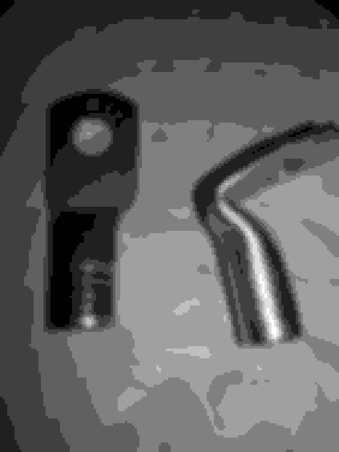
This is the main negative battery cable depicting midpoint grounding flag with 8mm hole and 6mm screw
stock negative battery terminal clamp has seen better days.
Access cover on side of lower fuse box. Simply pops open allowing access to negative battery cable.
Location of negative grounding point on engine side fender well
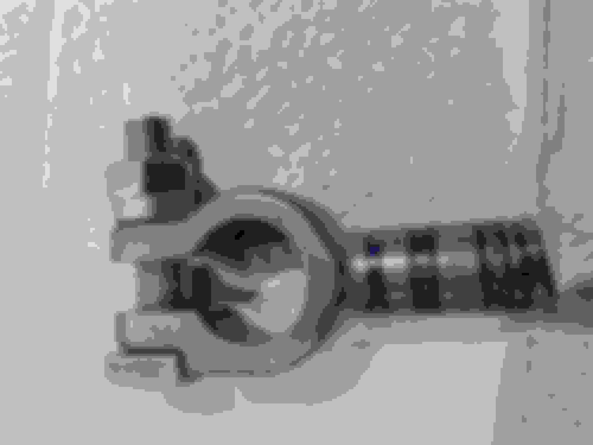
Quick Cable heavy duty lugs used for secondary grounding strap between right engine mount bade and body.
Old 6 gauge vs. New 4 gauge secondary ground cable. The original cable had broken strands and terminals were corroded., but not badly.for a 17 year old carm<br/>
Heavy duty tin plated cast copper negative battery lug contains premeasured dollop of solder in barrel eliminates need for crimping tool.
Quick Cable flag lugs available in 6mm and 8mm bolt hole.
Removing secondary ground strap
Quick Cable straight and right angle ground lugs for 4 gauge wire and 8mm bolt, heat shrink tubing and marine grade fine strand copper .tin plated. Quick Cable does not assign a P.N. to the right angle lug, so you have to order flat and bend...
This is a good post. I would be in for the group buy. I tried to address the negative cable about 2 years ago but there were no options available. I also snapped those battery tray studs so penetrating oil is your friend before trying to remove them. I should have known better but I sometimes things happen.
ClubLexus members frequently post inquiries listing engine, (especially ECU) transmission, body electronics and electrical systems exhibiting phantom performance issues.
In an effort to help.alleviate some of those issues, this posting focuses on negative grounding issues, and off the shelf solutions for 1995 - 2000 LS400s. (sone of which are applicable to other model and year Toyota/Lexus.)
One area that merits attention is the negative battery post clamp.
Ours consists of a rather flimsy circular copper ring which distorts over time and does not provide neessary clamping force over the negative battery post taper.
Resultong gaps between the negative battery terminal and mating cable clamp allow corrosion to nest resulting in increase resistance and voltage drop...
Anyone attempting to purchase a new clamp or negative battery cable assembly from Lexus learn Toyota determined not to sell replacement negative battery cables or clamps (as they do with the the positive terminal battery clamp) but expects you to purchase the entire wiring harness. (Lexus estimates about $1,000...not including installation)
Much of over the counter auto parts aftermarket negative cables and battery clamps are deficient.
I spent some time scoping out an engineered solution and located Quick Cable Corp in Franksville, Wisconsin; a battery cable supplier to heavy transportation OEM's, who offers a much improved range of standard battery clamps, terminals and battery cables.
I toured their production facilities and they actually manufacture what they sell..imagine that.
So, for those looking to replace only their negative battery clamp, Quick Cable offers OEM style in tin-plated copper clamp designed for 6 & 8 (Ls400 is 6) gauge to replace your tired original, part #850109-2001N.
Crimping is required...
Quick Cable also offers a substantially improved solution over the O.E.M. ring which is their FUSION series of cast copper, tin-plated connectors which contains a precisely metered amount of solder/flux in the barrel (wire entry point).
This eliminates the need for purchasing a crimping tool and possibility of corrosion between the cable wire strands and crimp connector (Lexus does use a dab of solder with theirs) which also offers the added benefit of decreasesing susceptibility to vibration and significantly increaeses pull out strength. Quick Cable P.N. ifor Negative side is 406304N which is compatible with 4 & 6 gauge wire.
It firther promotes decreased resistance and voltage drop....
This project uncovered more serious deficiencies in the main negative ground cable design in 1995 - 2000 LS400's... (Unsure if this effects 1990 - 1994...or for that matter, any or all other Lexus/Toyota products')
During LS400 prodution, on information the body shell is immersed in a tank containing a solution of paint, and, or corrosion resistant coatings....covering every nook and cranny...that's why the bodies on our cars outlast others...
However, if care is not taken this approach presents grounding issues.
On our cars, the main negative battery cable first connects to the body at the inner fender well via a flag terminal crimped at cable midpoint. (coated with solder and heatshrink)
There are several problems here...
First the terminal side mating to the body is attempting a ground to a painted surface and clamped with a thread forming type screw with captive washer.(last I checked paint was a much better insulator than conductor of electricity)
This bolt is threaded into a painted recess...the factory could have inserted removable plastic plugs at these points before painting...
Even more concerning is the flag terminal grounding bolt hole is 8mm, yet Toyota elected to use a puny 6mm bolt with improperly sized captive washer. SEE image.
So the only point power can travel is through the bolt head side of the terminal lug face..which first has to go through a too small diameter zinc plated steel washer, then a zinc plated lock washer, finally through the zinc plated steel bolt head which contacts the body via a painted tapped hole.
Dissimilar metal corrosion is a real concern here..aluminum(engine block), copper (cable and terminals) and steel (frame) are involved so Zinc plated steel fasteners works well between these elements.. .just the fit and quality of the fasteners could be improved..
DO NOT replace these with stanless steel or any other unplated material...stay with zinc plated steel!!
The solution was to replace the main negative 6 gauge OEM negative battery cable with marine 4 gauge finely stranded(increased number of strands) tin plated copper wire which offers increased current carrying capacity, reduced resistance &voltage drop, is more resistant to corrosion/oxidation and is much more flexible (finer wire strands less likely to fracture from engine vibration and movement over time) than the OEM's heavier (but fewer strands) unplated copper wire.
As I removed the cable and flexed it I could actually feel and hear a few broken strands crunching inside the insulation...
I plan to use. Quick Cable P.N.'s; 406304N for the negative battery terminal, 4 - 6 gauge tin-plated copper Left Flag terminal P.N. 850130D (grounding hole size matching 6mm OEM screw size) or if I can drill and tap an 8mm thread from the wheel well side by removing the tire, then P.N. 850130E. (probably best to purchase the 6mm flag and drill it out if you chose to undertake installing an 8mm bolt)Toyota uses solder at the flag terminal/wire joint after crimping...
Have not determined an optimum crimping method for this flag...which creates another possibility.
Quick Cable does sell a crimping tool but perhaps the more cost effective solution is to arrange for a group buy...or simply provide Quick Cable with a drawing so they can assign a P.N. produce both cable assemblies and allowing us to purchase from a distributor. Parts would include Negative Battery clamp, Marine 4 gauge wire, grounding flag, and grounding lug for AC Compressor.
The main negative cable was relatively easy to extract. First remove battery and battery tray (douse the bottom battery tray studs with PB blaster and let sit. If at all rusty they will snap right off when removing nuts...(Toyota elected not to use adequate corrosion protection on these fasteners). Trace the cable to the fuse box...open the side cover, cut(carefully!) through the electical tape until the cable is exposed and it seperates easily from the harness bundle. Next is one tiny black cable tie holding it at the fuse box door and a plastic body strap. Remove bolt at the air conditioner compressor and cable comes right out.
A secondary grounding strap runs from the right engine mount to the body.
Same paint issues as mentioned earlierm
Terminals exhibited modest corrosion....but some is too much.
Replaced with 4 gauge marine wire and heavy tin-plated copper lugs.
Also ran a tap through the body bolt hole to remove any paint... (!)
See side by side images or old and new cable withheavy duty lugs.
Broken enginei mounts can cause ground cables to fail...
Not sure of how a group purchase would work or the ClubLexus process but Quick Cable has suggested they could easily produce both cables as described above with stock parts they manufacture here in the U.S. and allow members to purchase with assigned P.N.'s through one of their designated distributors
A service tech at Lexus showed me a later model SUV that used grounding wire between body and transmission, therefore I was wondering whether adding a grounding cable between the transmission and body would help alleviate transmission issues.
The tech explained when the trans mount goes, so goes the ground strap....nothing a few more inches wouldn't resolve.
This is the main negative battery cable depicting midpoint grounding flag with 8mm hole and 6mm screw
stock negative battery terminal clamp has seen better days.
Access cover on side of lower fuse box. Simply pops open allowing access to negative battery cable.
Location of negative grounding point on engine side fender well
Quick Cable heavy duty lugs used for secondary grounding strap between right engine mount and body.
Old 6 gauge vs. New 4 gauge secondary ground cable. The original cable had broken strands and terminals were corroded., but not bad.for a 17 year old carm<br/>
Heavy duty tin plated cast copper negative battery lug contains pre-measured dollop of solder in barrel eliminates need for crimping tool.
Quick Cable flag lugs available in 6mm and 8mm bolt hole.
Removing secondary ground strap
Quick Cable straight and right angle ground lugs for 4 gauge wire and 8mm bolt, heat shrink tubing and marine grade fine strand copper .tin plated. Quick Cable does not assign a P.N. to the right angle lug, so you have to order flat and bend...
To maximize grouding, ran a tap through the body ground bolt hole to remove paint and any corrosion. The engine side bolt hole looked fine.<br/> Use anti-seize compound on threads when reassembling
OEM style negative battery post connector.. will require a specific crimping tool.
This image depicts secondary cable ground lug and thread cutting bolt which connects to body/frame. Both fastener and lug exhibit corrosion. Not bad for 17 years, but time to replace.
Last edited by YODAONE; 07-14-16 at 10:40 AM.
Reason: misspellings
Good post. And the area that is most prone to corrosion is the interface between the cable wires and the clamp, there is no way to tell for sure how bad it is, maybe a resistance check would tell, but still all an ohm meter would need is a small contact area to show its good. And when a larger current is needed that's when the problems would become more apparent. And you covered that. As far as the battery tray nuts after they have been removed use either Vaseline or battery terminal protectant on them and on the threads to keep the corrosion away. I would say do the same on the bolt that grounds to the frame. The tap idea is good but still at the factory when they tightened that bolt the friction would cause a good electrical contact. If there was paint in the treaded hole there would be problems running the bolt in the hole so I'm sure Lexus made sure body paint was not allowed in the threads, if there was they would have to chase the threads on the assembly line and don't think they wanted to do that.
If the body was dipped in something like galvanizing solution that is zinc and would conduct just fine. They would not dip in paint, there would be a rash of runs and drips everywhere.
This is a good post. I would be in for the group buy. I tried to address the negative cable about 2 years ago but there were no options available. I also snapped those battery tray studs so penetrating oil is your friend before trying to remove them. I should have known better but I sometimes things happen.
Does anyone have a spare negative battery - ground cable and body ground - engine cable? QuickCable has offered to produce an engineering drawing and assign a P.N. so membership can purchase from a designated distributor.
Would also appreciate feedback on suggested locations for placing a ground cable between transmission housing and body.(As Lexus does on newer models) using existing fasteners
The other place a dedicated ground is necessary is between top (steering wheel tilt side) and bottom of steering tilt column.. Grease is more an insulator than conductor of electricity... and I observe intermittent conductivity when the tilt and telescopic mechanisms are at different positions....
The original post presents images of the "Bolt W/Washer" hardware used to affix negative ground wire terminals #1 from negative battery post to the body and AC compressor; #2 between engine mount and body.
The hardware is essentially zinc-plated self-tapping steel bolts with integral washer and lock washer.
The first grounding point from the battery is a run through flag terminal at the fender well, which, as depicted earlier, the O.E.M. elected to use 6mm screw size in an 8mm flag terminal hole. (!!) A real concern is its puny captive washer hardly makes contact with the terminal lug; A.) because of the 8mm hole and B.) because of the flat washer's small diameter.
While waiting for the replacement cable assembly (will use flag terminal with 6mm bolt hole to match OEM ground bolt) I determined to address the fastener issue at this first ground point using an off the shelf Toyota part.
It is prudent to use zinc-plated steel bolts due to dissimilar metals involved...
Lexus p.n. 90080-11262 offered the 6mm diameter thread and larger washer.
New zinc-plated steel bolt with captive lock washer and larger captive flat washer provides increased contact with the terminal (remember the other side of terminal lug is resting on painted chassis).
Although I understand your gripes and applaud your effort these grounds did last for what most would consider a lifetime for mosts cars so I wound not blame the manufacturer for using crappy materials. Toyota definitely could have done better with the negative battery cable.
I have been having crazy idle issues for a while and tried a lot of fixes but nothing. This actually seems promising, thanks Yodaone!
I am game for a group buy, would make this easier. But since I'm sure this won't happen anytime soon, Yodaone, can you put a detailed list of all the parts, down to bolts and washers, so that way my noob self doesnt mess anything up?
I commute for school 5 days a week and work so I can't afford to mess up or order something wrong/miss a part.
The vendor is willing to produce both negative grounding cables...however requires an engineering drawing... Anyone who can do?
Yodaone - Thank you for this thread and the info! I find myself having to replace the negative cable on my 95 LS400 and this information is very helpful! So, did you then make 2 separate cables? One from the battery to the body and one from the body (same location) to the engine? If so, is that sufficient to handle the current without having the wire being continuous, like the original wire?
Another item to consider is all the electrical connectors for everything, like the fuses and relays, just simply pulling them out an reinstalling them will cause them to make good contact again. A guy on here just fixed his car removing and reinstalling a relay. Condensation is the cause as well as plain old oxidation and its likely to happen a lot when your car is exposed to salt air. So just like these pictures of grounds you can find the same thing where ever there is an electrical connection.
Wow! This is an awesome thread! I hope some one is willing to volunteer for this!
Courtesy of Fluke;
http://www.fluke.com/fluke/uses/comunidad/fluke-news-plus/articlecategories/electrical/diagnosevoltdrop
Electrical Automotive TroubleshootingDiagnosing Voltage DropOne of the most rampant electrical maladies showing up in automotive service bays today is the phenomenon known as voltage drop. Left unchecked, voltage drop causes countless unsolved electrical mysteries, especially when it infects the ground side of a circuit. It can also trick you into replacing parts that are not bad.
The more connections and wiring a vehicle has, the more vulnerable the electrical system is to voltage drop.
To contain electrical voltage drop, practice safe electrical service. This means measuring voltage drop before reaching any conclusions. "Voltage dropping" a circuit tell you when the circuit is too restricted to operate a component (motor, relay, light bulb, etc.) or operate it correctly. If the circuit is restricted, repair it and retest. If there is no restriction and the component still does not run or run correctly, then replace the component.
In this example, if the water pipe completely collapses, water stops flowing, pressure drops to zero and the water wheel stops turning. Electrically, the same thing happens when a wire falls off or a connection breaks. Current stops flowing, voltage drops to zero. A starter motor would quit or a headlight would go out.
Symptoms of voltage drop
Often confusing and contradictory, electrical voltage drop symptoms vary according to the circuit's job and the severity of the voltage drop.
inoperative electrical parts
sluggish, lazy electrical devices
erratic, intermittent devices
devices that work sluggishly or erratically during periods of high electrical loads
excessive radio interference or noises in the radio
damaged throttle or transmission cables or linkage
repeated throttle or transmission cable failures
damaged drivetrain parts
engine or transmission performance complaints
no-starts or hard starts
high sensor or computer voltages
erratic engine or transmission computer performance
false trouble codes in the memory of any on-board computer
premature or repeated A/C compressor clutch failure.
This symptom list brings up several points.
Visual inspections miss most cases of electrical voltage drop. You usually can't see the corrosion inside a connection or the damaged wire that is causing the problem.
Ground-side voltage drop, a commonly overlooked cause of electrical trouble, can cause most of these symptoms. Any circuit or component is only as good as its ground.
The more sophisticated electrical systems become, the more important their grounds are. The number of electrical components has increased rapidly and most do not have separate ground wires. Instead, these devices are grounded to the engine or body. Rust, grease, vibration and/or careless repairs often restrict the circuit from the engine/body back to the battery.
Many components such as engine sensors share a common ground. Therefore, a bad ground complicates diagnosis because it affects several components at once.
Some shop manuals and diagnostic charts or fault trees recommend checking grounds last. In reality, it is much quicker to check ground circuits before you climb that fault tree.
It's quicker and smarter to routinely check a circuit's voltage drop than it is to memorize long lists of symptoms. If experience has taught us nothing else, it's that chasing symptoms is no substitute for routine and thorough voltage drop testing.
Experience has taught us other reasons to check voltage drop first. Voltage drop, usually on the ground side, causes inaccurate or bizarre voltmeter readings and oscilloscope patterns. Moreover, when you connect a voltmeter or scope to a system with bad grounds, the test equipment itself can create a good substitute ground. This can be frustrating: as long as your equipment is connected, the circuit works and you can't find anything wrong!
Basic procedures
Whenever an electrical problem gives you fits, take a deep breath and think of the basic electrical building block, the series circuit. Drawings 1 through 7 show basic series circuits. No matter how complicated a system is you can always simplify it into mini-series circuits. Then, inspect each circuit for voltage drop.
Also, relate electricity to water flowing through a water circuit. Water pressure inside the reservoir pushes gallons of water through the pipe. The water turns the water wheel and then flows back into the reservoir. In an electrical circuit, electrical pressure (voltage or volts) pushes electrical volume (current or amps) through the circuit, operating a load. The load may be a computer, a motor, a lamp, a relay, or other device. In the water circuit, the water uses up most of its energy turning the water wheel. Water continues flowing toward the reservoir, but it flows at a lower pressure.
Likewise, electrical pressure (voltage) is used up operating the load. Therefore, voltage falls to about zero on the ground side, but current keeps flowing toward the battery. Because the voltage in a healthy ground circuit should be about zero, some technicians call it ground zero.
A kinked return pipe restricts water flow back to the reservoir, slowing down the water wheel and causing a pressure reading on the return side of the wheel. Likewise, ground side voltage drop hurts load performance and causes a voltage reading at the ground side of the load.
Resistance�Restriction
When you think of excessive resistance, imagine a dent or kink that is restricting water flow through a pipe. Common sense should tell you that a kink anywhere in the water circuit (supply side or return side) restricts water flow, causing the water wheel to slow down or stop turning.
Excessive resistance has the same effect on an electrical circuit. Bad connections and broken or under size wires act like a pipe with a kink, restricting current flow. Like the water circuit, restricting current flow anywhere � hot side or ground side � hurts the performance of the load. The effect on the load is hard to predict because it varies with the severity of the restriction. For example, the motor in a restricted circuit may stop working or just run slower than normal.
A restricted circuit can cause an A/C compressor clutch to slip and prematurely burn out. A computer on a restricted circuit may shut off or else work erratically. When corrosion, loose connections or other types of resistance restrict a circuit, volts and amps both drop. If volts drop, amps drop too. That is why when you find a voltage drop in a connection or cable, you know the connection or cable is restricted.
Look at the water circuits in our drawings and remember two critical points. First, a free-flowing ground side is as important as a free-flowing hot side. Second, a ground side restriction is the only thing that causes voltage readings greater than 0�0.1V in any ground circuit.
A completely collapsed return pipe stops water flow, stalling the water wheel and causing a system pressure reading at the return side of the wheel. Likewise, a broken ground wire totally blocks current flow, shuts off the load and causes the ground side of the load to read system voltage.
Voltage drop tests
Electrical voltage drop varies according to current flow. Unless you operate the circuit so current flows through it, you can't measure voltage drop. Because an ohmmeter's battery can't supply the current that normally flows through most circuits, ohmmeter tests usually can't detect restrictions as accurately as a voltage drop test.
Open-circuit problems such as broken or disconnected wires or connections stop current flow. After you fix an open circuit, switch the circuit on again and check for lingering voltage drop. Until you get current flowing and check the circuit again, you can't know if the entire circuit is healthy.
Although resistance-free connections, wires and cables would be ideal, most of them will contain at least some voltage drop. If your manuals do not list voltage drop values, use the following as maximum limits:
0.00V across a connection
0.20V across a wire or cable
0.30V across a switch
0.10V at a ground
Because most computer circuits operate way down in the milliamp range, they don't tolerate voltage drop as well as other circuits do. Note that a milliamp is one-thousandth (0.001) amp. The recommended working limit is 0.10V-drop across low-current wires and switches. Testing low-current circuits also requires a high-impedance (10-megohm) voltmeter. A low-impedance voltmeter may load a low-current circuit so much that it gives an incorrect reading or no reading whatsoever! Most professional-grade digital multimeters (DMMs) have 10-megohm input impedance. Using a DMM is the fastest way to accurately measure voltage drops. If the DMM you own does not have autoranging capability, use a low-voltage (0-1 V) scale for voltage drop testing. Remember that test lights are not accurate enough to diagnose electrical voltage drop.Quick ground tests
Because ground circuit voltage drop can cause most of the symptoms listed earlier, consider adopting this new work habit: test grounds first! Before you do a tune-up, check out electrical problems, or test a starting, charging, ABS or air conditioning system, routinely test the engine and body grounds. Connect your DMM between the engine and negative battery terminal. Safely disarm the ignition and crank the engine for a few seconds.
If the voltage drop is excessive, repair the engine ground circuit and retest. Note that on some distributorless ignition systems, the simplest way to prevent the engine from starting during the ground test is to pull the fuel pump fuse. Next, connect the DMM between the negative battery terminal and the vehicle's firewall. Then start the engine and switch on all the major electrical accessories. Too much voltage drop? Then fix the body ground and retest.
Once engine and body grounds are within limits, proceed with your diagnosis. Do not be surprised if fixing these grounds solves the car's problems. The fact that a vehicle passes the body ground test does not mean you can safely ground your voltmeter wherever you want. Some technicians have run themselves in circles for hours because their voltmeters were not well grounded. For safe electrical service, make yourself a 20- or 30- foot jumper wire with an alligator clip on each end. When you have to test an electric fuel pump, lighting system or ABS computer in the rear of the vehicle, ground your DMM to the battery with the jumper wire.
Computer ground kinks
Because computer circuits operate on such low current, the standard ground tests may not reveal a marginal ground on an on-board computer. Before you condemn any on-board computer, check its grounds first. Operate the computer system and backprobe each computer ground terminal. If you measure anything greater than 0.10V, trace that ground circuit and locate the problem.
Sometimes, computer grounds are connected to a spot where they are easily disturbed or prone to corrosion, such as a thermostat-housing bolt. Computer connector terminals also can corrode. Removing the connector and spraying the terminals with electrical cleaner may be all it takes to eliminate the voltage drop.
Experience shows that as little as 0.30V on a computer ground terminal can cause trouble. Try pinpointing that with a test light! Poor computer and/or sensor grounds can cause higher-than-normal sensor voltages and false trouble codes. In many cases, the bad ground prevents the computer or sensor from pulling a voltage signal down to or near ground zero. Sure, accessing the computer to check grounds may be a hassle. Nevertheless, mistakenly replacing expensive sensors and computers is a bigger hassle.
Connect a DMM across part of a circuit and it directly reads the voltage drop across that wire, cable, switch, or connection. Here, one DMM would display the voltage loss between the battery and the load. The other would show the voltage loss from the ground side of the load to the battery.
Body ground gremlins
Keep your eyes peeled for missing body grounds. If someone else worked on the vehicle, he may have forgotten to reconnect body ground wires or cables. Remember that when the body ground is restricted, current tries to find another route back to the battery. The easiest alternate route may he through the transmission shift cable or the throttle cable. Not only can this current weld the cable together, it also can pit or erode bushings and bearings inside the transmission.
If you find the insulation on the body ground wire is burnt or blistered, you can bet that starter current overheated the wire. When the engine ground is restricted, starter current tries to return to the battery through the body ground circuit. Experience shows that if the body ground circuit can handle the current load, the customer may not notice the problem right away.
Under periods of heavy current flow, a restricted body ground may hamper or shut off a component. For example, turn signals have been known to stop blinking when the driver steps on the brake pedal. Testing confirmed that a restricted body ground choked off the turn signals. The ground could not handle current from the turn signals and brake lights at the same time.
Safe service
Practicing safe electrical service helps you solve electrical problems quicker and more profitably than guessing and swapping parts. Put your DMM to work wiping out electrical voltage drop today. It is the responsible thing to do.
As reported earlier in this posting, the main negative battery cable grounds to the inner fender well via a flag terminal before terminating at the Air Conditioner Compressor.
This post focuses on the compessor terminus
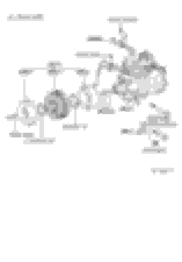
The air conditioner compressor housing is comprised of Aluminum, so grounding a copper cable with copper lug mating to that surface would react-oxidize-corrode, etc, in short order.... It would appear Toyota determined to use an L-shaped "Compressor Stay" between the ground cable and compressor to avoid dissimilar metal corrosion .
This plate and fastener assembly corrode over time resulting in increased resistance and voltage drop...
As this terminus is near the bottom of the engine, those running without the bottom engine cover are more susceptible to accelerated ground degradation...especially if you run in salted roads. Main negative battery cable terminates at the AC Compressor and Oil filter housing bracket.. Lexus incorporated a plated metal compressor stay. The original on this 99 LS400 is tired. This original compressor stay is from a well maintained 1999 LS400...both plate and hardware have experienced better days. Older LS400's surveyed are far worse... The replacement compressor stay has a different finish than the original dichromate finish(? Used a test meter and this black finish proved conductive. The bolt and nut are steel, generously Zinc-plated. The L-shaped Compressor Stay grounds to the engine block at oil filter bracket housing via the hexagon-shaped spacer shown. Plenty of corrosion depicted here. Not replaced, but will be upon next parts order. Compressor Stay is 88431and nut is 90179-08037 in Lexus exploded parts diagram. The negative ground strap mounting bolt is not depicted...and was unable to locate a specific part number in the Lexus system.....perhaps a member can advise. (The bolt I used was the engine-to- frame ground strap bolt...the clamping washer is smaller however it is not an inferior thread-cutting/forming style bolt) Anyone with a P.N.? The Compressor Stay ground plate straddles oil filter bracket hex standoff bolt # 90116-08319..The original is corroded which would respond well to replacement.
 07-14-16, 12:21 AM