When you click on links to various merchants on this site and make a purchase, this can result in this site earning a commission. Affiliate programs and affiliations include, but are not limited to, the eBay Partner Network.
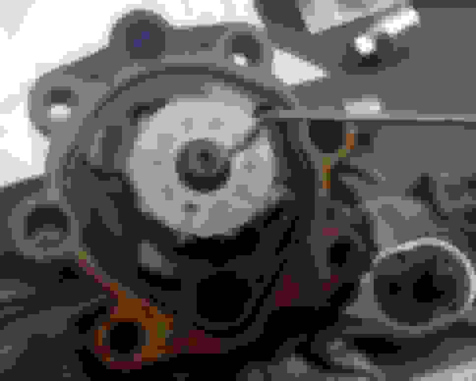
Step 14: Remove the cam ring, 10 vane plates, and vane pump rotor
(DO NOT DROP THE PLATE)
Before removing the cam plate, take note of the placement of the vanes. They are beveled on one side and that bevel faces out towards the edge. You MUST replace these vanes in the correct orientation or the pump will not work correctly and you will damage it. There are marks on the cam ring and vane rotor faces for proper installation. Do not simply reassemble in reverse order - follow the installation instructions below!
Also, note which holes the straight pins are in.
Once you remove the cam ring, the vanes will simply fall out, so make sure you are doing this close over a table so the vanes don�t get lost.
Vanes removed.
Last edited by thaeleelyr; Apr 10, 2016 at 05:29 PM.
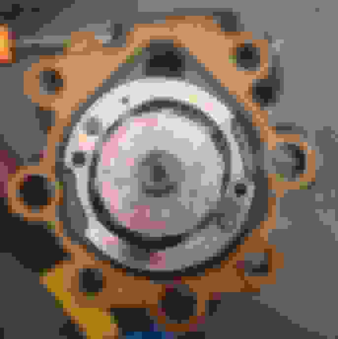
Step 15: Remove the snap ring and vane pump rotor from the vane pump shaft.
Below is a photo of the snap ring just prior to being removed. The vanes should not still be in the vane rotor when you remove the snap ring, so be sure to remove yours before taking it off. Also, you can�t quite tell but be sure to support the vane pump shaft. I�m using a rag and a ratchet for this. (I didn�t think to use the masking tape roll until later)
This is a photo of all but the straight pins removed and only the shaft left, ready for removal.
Remove the snap ring and pull out the vane pump shaft. It is removed by pushing the shaft towards the front of the casing where the pulley sits (in this photo, towards the left). You can see the shaft partially removed.
Step 18: Reassembly Start: Inspect elements & clean up
Clean up the parts and inspect them for any scoring, warping, etc. There are specification for the vanes and vane rotor that require a micrometer, but I don't know where you would get replacements so I didn't do them.
About the only component that can be partially tested without specialty tools is the flow control valve.
Flow Control Valve Test: Coat the flow control valve with power steering fluid and check that it falls smoothly into the flow control vale hole by its own weight. If you need to replace the flow control valve, do so with one that has the same letter as inscribed on the front housing: A, B, C, D, E, or F
If you left the pins installed, be sure to cushion them for seal installation. Wrap some newspaper around the pins and place the unit on top of a cushioned handle, being sure that the pins straddle the handle and are not touching the work surface. Once you have provided enough area of support tap the new oil seal into place with a rubber mallet while keeping the pins off the table and undamaged.
Install the vane pump shaft with the inscribed mark facing outward. Install a new snap ring to the vane pump shaft. At this point I stacked a couple of masking tape rolls and placed the front housing nose down on top. Once the housing was together I switched to the bench vise to torque bolts. Alternately, use a bench vise from the beginning but don't squeeze too hard on the casing.
!! Install the 10 vane plates with the beveled (rounded) end facing outward. !! Be sure these are well coated in power steering fluid.
Initially I had arranged the vanes as they were installed with the intention of placing them back in their exact same spots. I still think this is a good idea since I didn�t measure any of these components but that didn�t work out due to my own incompetence. Fortunately the pump still works. The most important thing is to get the vanes installed facing the correct way.
In this photo the shaft, shaft snap ring, vane rotor and vanes have already been installed. You can see they have been well doused with power steering fluid.
Install a new gasket facing the correct direction as shown. My gasket had a rubber seal. I made sure the mating surfaces were clean and smooth. I don�t recall using any kind of gasket maker with this.
Step 26: Install Rear Housing & O-rings
Coat 2 new O-rings with power steering fluid. I found it easier to install the larger O-ring directly onto the side plate and the smaller O-ring in the rear housing, otherwise the large O-ring tended to fall out while installing the rear housing.
Install the rear housing with the 4 bolts (17 ft. lbs.)
Step 27: Install Spring, Flow Control Valve and Pressure Point Union
Install the spring, then the flow control valve (be sure it is facing the correct direction). Coat a new O-ring with power steering fluid and install it onto the pressure port. Then install the Pressure Port Union (62 ft. lbs) with the large socket.
Step 28: Install Suction Port Union
Coat a new O-ring with power steering fluid and install it to the suction port union. Install the suction port union with the bolt (9 ft. lb) with the 14mm (?) socket.
Step 29: Install the Front and Rear Brackets
Torque the three bolts to 32 ft. lbs.
Step 30: Install the Vane Pump Pulley
If you don’t have the pump in a vise, do so now as you did to remove the pulley. Brace the pulley and torque the nut to 32 ft. lbs.
Step 31: Measure the PS Vane Pump Rotating Torque
If you have the type of torque wrench that checks torques/foot, the rotating toque should be 2.4 INCH / lbf. OR LESS. I didn’t have one, so I didn’t do it. I wouldn’t rotate the pump too much at this point.
Step 32: Install the PS Pump onto the vehicle.
Temporarily install the pump with the two mounting bolts. Do not torque these bolts yet. The instructions I had stated to install the belt next, but I installed that last after I attached all the hoses.
Step 33: Connect the Pressure Feed Tube
Install a new gasket and connect the pressure feed tube to the pump with the union bolt. My kit didn’t contain this gasket, so I had to reuse mine. Be sure to seat the stopper on the tube against the front bracket, then torque to 38 ft. lb)
Step 34: Install the Oil Pressure Switch
Torque to 15 ft. lb, then connect the wire harness.
Step 35: Connect the Return Hose
Using the squeeze clip, connect the return hose.
Step 36: Install the belt and Tighten
Install the belt and tighten it to spec. The belt tension should be 22 lbf. Using a belt deflection tool, adjust the belt tension until it is 7-9 mm for a new belt or 10-12mm for a used belt.
The top bolt is torqued to 22 ft.lbs, the bottom adjusting bolt is torqued to 32 ft. lbs.
Step 37: Bleed the System
- Fill the power steering fluid reservoir to proper level.
- Jack up the front of the vehicle
- With the engine off, slowly turn the steering wheel from one lock position to the other.
- Lower vehicle and start engine
- Run engine at idle for a few minutes
- With the engine idling, turn the steering wheel to the left (or right) full lock position and keep it there for 2-3 seconds; then turn the wheel to the opposite full lock position and keep it there for 2-3 seconds. Repeat this step several times
- Stop engine
- Check for foaming or emulsification. If the vehicle has to be bled twice specifically because of foaming or emulsification, check for fluid leaks in the system.