When you click on links to various merchants on this site and make a purchase, this can result in this site earning a commission. Affiliate programs and affiliations include, but are not limited to, the eBay Partner Network.
Activate rear view camera with left/right turn signal?
I’m on vacation for the rest of the year starting Friday and wanted to install a backup camera over the break so I ordered the NavTool and the Alpine HCE-C155 wide-view camera. I’ve read over several install threads and the job seems pretty straight forward as far as the backup camera function.
However on one of the threads, someone came up with an idea where the backup camera could also be activated by the left/right turn signals so you could see behind you while changing lanes or left/right hand turns. The idea lived for a few more posts on that thread but never came to fruition on how to do it.
If it hooked up directly to the rear blinker line it would turn on and off with each click of the blinker switch and I don’t want that. So I’m thinking something that would work with the blinker switch and keep the circuit open long enough for the next click of the blinker and shut off after the last blinker click. I’m hoping Retroplay or anyone for that matter would have some insight on what that something might be?
I once bumped the gearshift into reverse on the highway and that activated the camera -- luckily no effect on the tranny. But scared the crap out of me.
I once bumped the gearshift into reverse on the highway and that activated the camera -- luckily no effect on the tranny. But scared the crap out of me.
Simple switch under dash connected to reverse lights can be used to engage the camera just like when you go in reverse. That's how mine are and I can at will turn it on while driving forward and see who or what is in my blind spot.
Thanks guys, just what I was looking for. I can connect wires but know nothing about electronics. However I do play an IT architect in real life so I can represent just about any component with boxes and lines. I don’t think I need the Bosch Relay because I think the NavTool plays that role as far as switching power to the camera.
The component I was looking for was something to keep the +12V constant during the intermittent clicks of the turn signal switch;
Basically my representation of the above component added to the NavTool instead of the Bosch Relay and using the same +12V as would the Backup signal;
So for you electronic guys will this work and what happens if I use the turn signal while in reverse, will it fry the NavTool with two +12V inputs in parallel?
Same level voltages in parallel will not cause issues. The Nav Tool is designed to handle 12 V already, placing another same voltage (12 V) in parallel will only present 12 V to the Nav Tool. Just make sure to insert a diode between the 12 V backup signal and the circle like you did with the turn signals. You don't want to back feed the voltage to whatever circuitry is involved with the back up signal. (If the back up signal source is only a physical switch, then you are okay without a diode.)
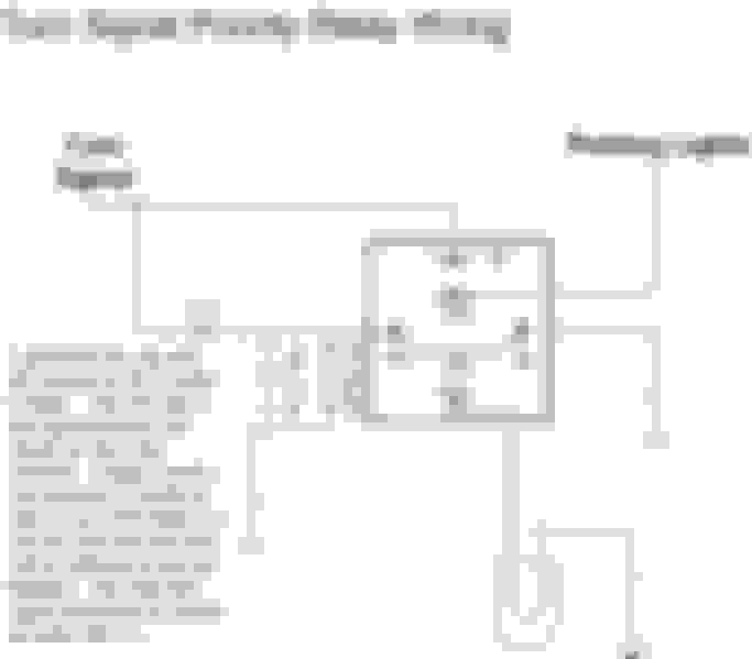
Here's an electrical diagram of the turn signals, unfortunately, it doesn't show the actual turn signal switch. However, if you connect onto the turn signal relay pin # 3, I'm guessing that will be 12 V constant when the turn signal switch is activated. I believe that this relay is just above the steering column. (The relay is T15 on page one of the attached diagram. By attaching here, you won't need the RC circuit to convert the alternating signal into a constant signal.)
Thanks again guys, this was very helpful. Obviously the direct line from the turn signal switch is the cleanest route but a pain to run a wire from the steering column to the trunk. I got the time so maybe I’ll go that route but assess how much stuff I have to take apart first before I make a decision.
The Alpine HCE-C155 was recommended on one of the threads from this Forum and I think is the most expensive camera options out there, the least expensive one I could find was on eBay for $179, most everywhere else they are over $200.
I picked that model because of the high quality image and wide 190 degree view exactly for the turn signal application, I hope it was worth the extra $$$. I'll let you know how it turns out.
Question; Has anyone done this already, how did it work out?
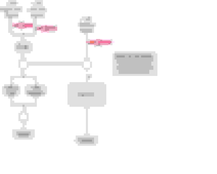
You can play around with the capacitor value to get the signal to stay at +12V in between flashes. It will also continue an output for that same duration after the last blink. The only issue I see with your circuit is feedback. You must isolate the Right from Left flasher bulbs with diodes placed in the line from the bulbs to prevent both sides from flashing when one is on. Additionally, another diode is needed to prevent feedback to the Reverse Light when the flasher are on. Indicated by the Red arrows.
Never tried what you are planning, but if it were me, I'd use the relay. A little more circuit isolation.
I’m on vacation for the rest of the year starting Friday and wanted to install a backup camera over the break so I ordered the NavTool and the Alpine HCE-C155 wide-view camera. I’ve read over several install threads and the job seems pretty straight forward as far as the backup camera function.
However on one of the threads, someone came up with an idea where the backup camera could also be activated by the left/right turn signals so you could see behind you while changing lanes or left/right hand turns. The idea lived for a few more posts on that thread but never came to fruition on how to do it.
If it hooked up directly to the rear blinker line it would turn on and off with each click of the blinker switch and I don’t want that. So I’m thinking something that would work with the blinker switch and keep the circuit open long enough for the next click of the blinker and shut off after the last blinker click. I’m hoping Retroplay or anyone for that matter would have some insight on what that something might be?
You wish to also retain the backup capability, correct? And you also want it to switch whenever you turn in either direction?
And some random thoughts while I am thinking about it:
The flasher relay appears to be 3 pin. It works by using the steering column switch to present 12V to either the left or the right side turn lamps. The relay alternates sinking that voltage to ground.
In order to mix either turn signal, you could install a small value resistor in line between the relay and ground. When the turn signals are on, you would get 12V across that resistor. So then only one signal to deal with for either turn signal.
Technically, the LEFT/RIGHT voltages are supplied by the RH J/B ECU. For some reason, I am missing the wiring from the steering column switch to that ECU. I also am not sure of the location of the J/B ECUs. BGW70 may be able to help with that.
And last thought, the RC filters showing would work fine. The only issue could be that the voltage drops from 12V to zero gradually. I am not sure if that would cause an issue with the NAVTOOL input. Probably not.
A cleaner way to do it would be to use a simple 555 timer circuit to get a clean on/off pulse of the duration you want. Another benefit is that you can then adjust it. I will see what I can come up with later when I have more time.
Thanks Retroplay, this just got really easy. Your idea of a timer circuit got me thinking on Google for 12V Timer Relays and I found something (I think?) that may work and make this job so much easier.
The only thing is minimum delay set is 2 seconds which I think works out perfect because when changing lanes most of the time I just flip the turn signal bar long enough to get one left/right blink to be legal, the relay would keep the camera on for 2 seconds after that which would be just enough time to physically make the lane change and then switch off. Or I can search around for a relay with a shorter delay which I've already came across a few but this one looks the easiest to use.
 12-15-15, 02:51 PM