When you click on links to various merchants on this site and make a purchase, this can result in this site earning a commission. Affiliate programs and affiliations include, but are not limited to, the eBay Partner Network.
Full Illumination Climate Control Light Replacement Write-Up W/Pics
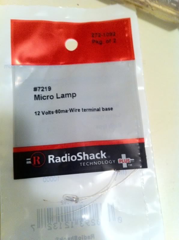
Under heavy request via PM, I've finally gotten around to thie write-up with Pics. Basically, this will take the 272-1092 Radio Shack Bulb (readily available for $2.00 for a two pack and give FULL ILLUMINATION instead of half -illumination that you get when replacing the bulbs. You will need a large Phillips, a small Phillips, soldering iron, solder, piece of 18ga wire (about 5") and a 10mm socket. Remove shifter, Remove center console (6 screws, two under the cup holder, four under the shift console) and remove radio / climate control cage (4 phillips screws, 2 10" bolts) then separate climate control unit from cage (four black phillips, two on either side.)
Buy these bulbs from radio shack (they will work for the button lights as well, so buy a bunch of them, they are cheap! The also work for hazard switch light, ECT switch, etc... May as well change them all while you have them out!
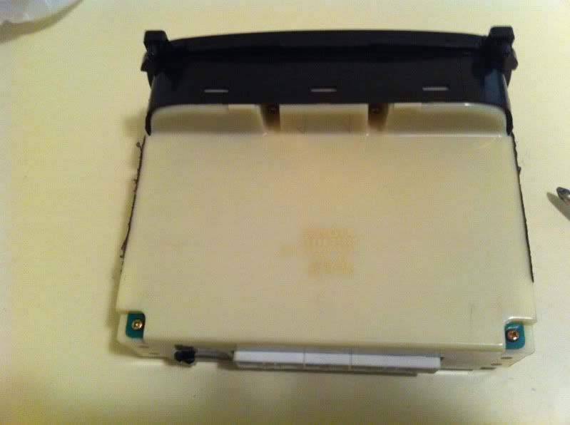
You now have the unit out of the vehicle to modify / repair:
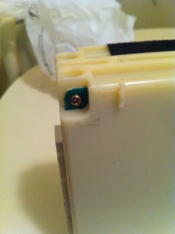
Remove ALL 6 EXTERIOR SCREWS, four at the corners:
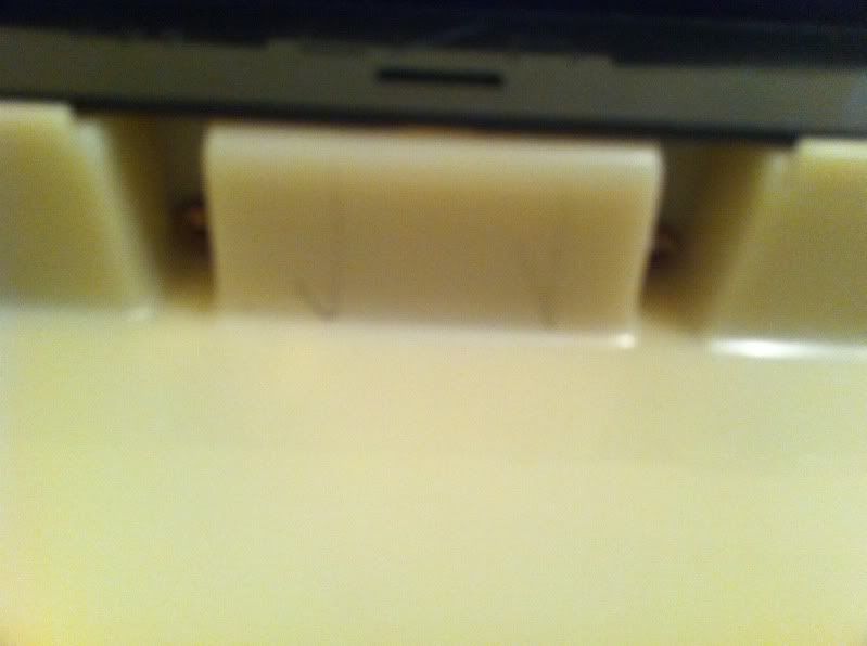
Two inside these indentations:
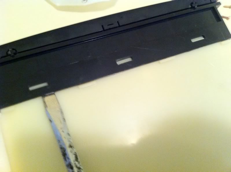
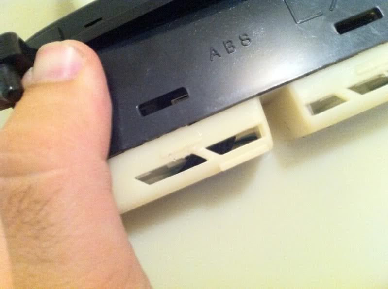
Separate face from unit by gently prying with a flathead under the retaining tabs (six in total):
Gently apply pressure while prying:
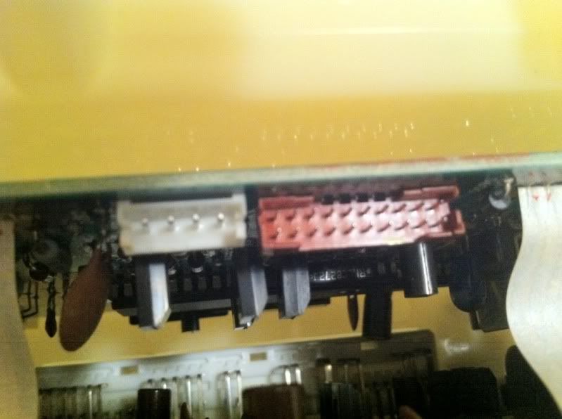
Remove these cables from the backside of the unit by gently pulling:
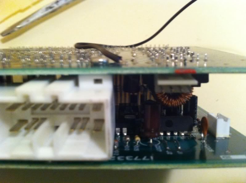
We were trying to get power from the left (from this vantage point) connector without splicing wires, or not being able to easily remove unit from vehicle.
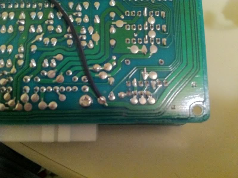
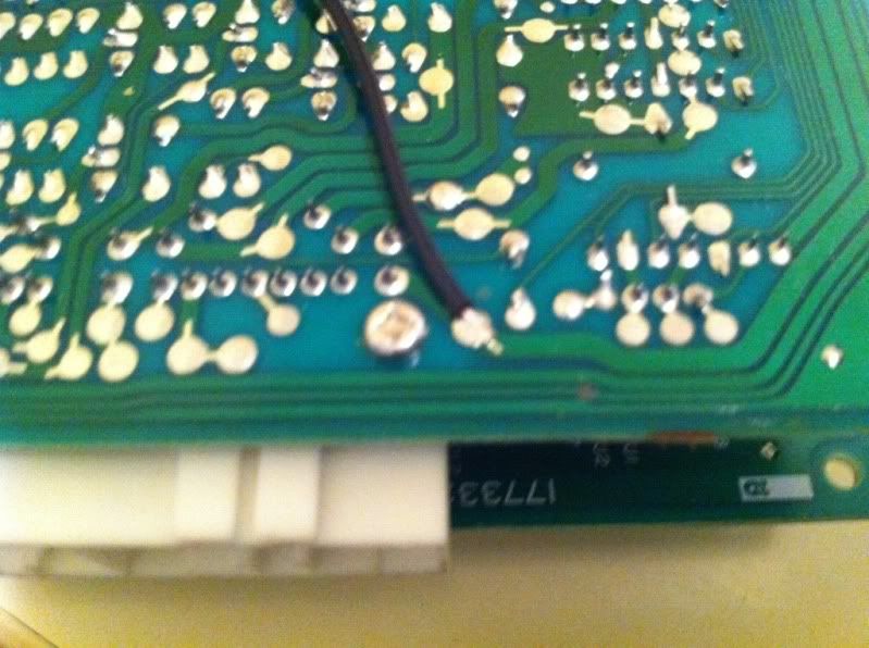
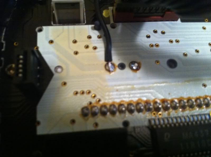
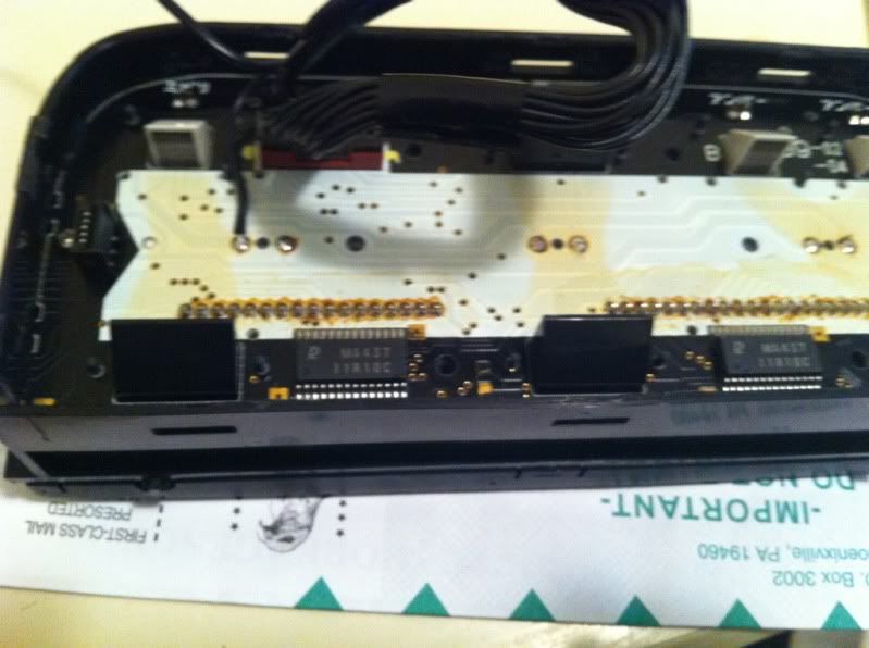
Slide Circuit boards from back of unit and turn over to expose solder points for harness receptacles (I have already soldered the wire we will be adding):
Solder the wire you are adding to this solder point (nothing is connected to it a this point):
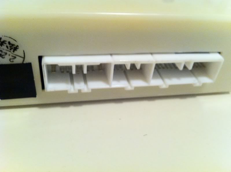
Use this connector for reference where to solder:
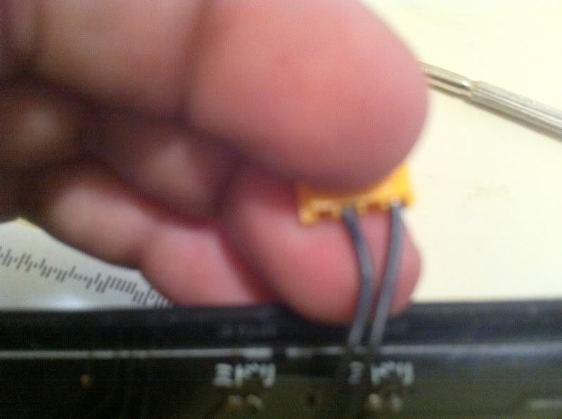
Now, from the two harnesses connecting the front of the unit (face) to the rear (circuit board, or "brain" you will be removing a pin from the smaller one (3-wire).... Mine Pictured is already modified... The wires are grouped in the following manner in the four pin connector [ll_l] you will be removing the end wire from the two grouped together, and taping it up (full reversible) so you will end up with [_l_l] here it is completed:
Now we will be modifying the face of the unit, you will NEED TO REPLACE ALL 3 BACKLIGHT BULBS with the Radio Shack bulbs. I did not take pictures of this because I've already completed this, and it is very fragile to move the LCD screen to access these bulbs without de-soldering the entire LCD, but it CAN BE DONE, and mine has been in 4 months of extreme changes in climate without bleeding. You can search to find posts on how to replace the bulbs. After you replace the bulbs, you will be soldering the wire you added to the motherboard of the backside of the unit, the trick is that, on the third bulb the polarity is reversed on the solder points, so solder the right (looking at the front of the screen as you usually to to see the display, or the left looking at the rear where you will be soldering. and solder the wire to the outermost pin where you soldered the new bulbs into (next to the header where the button light ribbon cable connects:
Re-assemble the unit in reverse order, replace in vehicle, and enjoy! I know I missed a few pictures, but you can fill in the blanks with another post on replacing the bulbs, and I can also answer questions... If anyone who created the original posts that stand on replacing just the bulbs would like to donate their pictures to fill the blacks in, I would appreciated it, and give credit for them. Feel free to ask questions!
When you replace the backlight bulbs in the climate control unit with anything but toyota bulbs you get about half the original brightness, this fixes that for MUCH, MUCH cheaper, and easier to find bulbs.
Been searching all evening and found this thread. I just replaced the LCD on the climate control. Now I need to replace the backlight and button bulbs. As pictured below.
I just want to make sure I get the correct bulbs so I just want to confirm if these are the bulbs I need to replace the backlighting and button bulbs with. I read from another thread that these 12v microlamps will do the trick instead of the 6v ones. http://comingsoon.radioshack.com/12v...l#.VWVeRM9Viko
I replaced my LCD but I lost my illumination in the process, what went wrong? What is the power lead in the harness for the backlight so I can trace out? is it ACC power source?
 05-30-11, 04:26 PM