When you click on links to various merchants on this site and make a purchase, this can result in this site earning a commission. Affiliate programs and affiliations include, but are not limited to, the eBay Partner Network.
This guide is for use of factory 2JZGTE ecu's on NA-T with coil on plug conversion.
I made some diagrams to help people understand whats needed for the TT ecu mod.
This thread shows wiring for vvti coilpacks, which are newer generation coils found on the 1jzgte vvti, 2jzge vvti and 2jzgte vvti.
The bonus is that these coils will fit under the stock 2jzge intake manifold without modification and they are excellent coils.
There is also a way to do this mod without the coilpacks and keeping the stock distributor and coil.
This cuts down on quite a bit of wiring and you can still upgrade to coilpacks whenever you want.
See post 4 for that, I am going to leave post 1 with the coilpack version of the mod since its the complete mod.
This thread has grown rather large with a lot of info spread out on different pages, so try using a google search + tt ecu mod to try and find what you are looking for. If you cannot find it or have a old/new question, just post it at the end of the thread as its just an ongoing discussion and tech help at this point, its alright even if its been asked before it can be a little challenging the first time you do the mod.
So, Onto the good stuff. From here you must make a choice that will affect the parts you need to perform the mod.
There are 2 choices.. Choose your destiny... USDM 2JZGTE ECU or JDM 2JZGTE ECU
simple right..? not really but majority should just go ahead and use the JDM 2JZGTE ECU which is the proven setup and works with most common na-t setups.
all 2jzge and 2jzgte non-vvti have the same ecu connector so that is the starting point for this mod, we can plug in several different ecu's.
For 2JZ-GE's that are 92-95, I recommend using a JDM ecu 100%. its map sensor based and is proven to run na-t very well.
For 2JZ-GE's that are 96+ non vvti, I still recommend using the JDM ecu as its map sesnor based and works with na-t the best.
The wiring is a little different, but basically you tap the tps for map sensor power and ground instead of the old maf plug as the newer mafs are 12v vs older ones are 5v and tps is 5v also.
IF you want to try and have an obd2 compliant ecu then there is sort of an advantage to using the USDM ecu as you can keep odb2 working. The wiring is a little different we don't reuse the maf wires for the map so see post 4 for that. *DISCLAIMER* setting up the US GTE ecu's with a maf can be quite a pain to get them to run without misfire codes. members have tried piggybacks etc.. they don't seem to work too great. I would recommend avoiding this combination.
If you are 98+ vvti, then you have to use a JDM VVTI 2jzgte ecu but odb2 port will not work. The VVTI 2jzgte was never offered in US.
The 2jzgte vvti and 2jzge vvti have the same ecu connector, but its not the same as non vvti connector, so you are stuck with this ecu but the good news is you already have the right coilpacks, ignitor and most of the wiring, and once done it will control vvti like a gte would.
You need the gte maf it will plug in, and a map sensor added to keep the ecu happy. This has been tested now and works well for vvti setups.
Now that we touched on the year ranges and an idea of what ecu you should look to use, I want to mention about transmissions.
The tt ecu mod does not control the torque converter lockup on the GE transmissions. this function does not work.
The GE trans will shift through all the gears, it just won't lock/unlock the torque converter.
If you have to stay auto I would recommend swapping to a GTE Auto transmission but it will take extra wiring not covered here.
What I really recommend is swapping to a manual transmission that will hold the power, like an R series trans with a nice clutch (consider twin options for better street-ability) or nowadays the T56 is a great option for big power but it is pricier overall.
So, this write up is focused on 92-95 using the JDM ecu and VVTI coils, that is what most will end up using as it is just map sensor based. Skip to post 4 for info on using a USDM ecu 96-97 (you will need a TT maf and TT map, and get 550cc injectors instead of the 440cc) See post 4 for wiring up the stock coil/distributor instead of a vvti coils (still need a ds62 ignitor though) See post 4 for wiring up TT ignitor/coils instead of a vvti ignitor/coils (must have a Font Facing Intake Manifold) See post 4 for wiring up 1ZZ/2ZZ coils instead of a vvti ignitor/coils (must have a Font Facing Intake Manifold) See post 4 for wiring up GM LQ9 coils (requires an IGF simulator/faker).
Parts for JDM ECU:
TT ecu: Jdm Aristo or Supra ecu (aristo is more common and always auto; supra has auto and manual ecu's)
injectors: 440cc (stock size and plug and play), or you can run up to 550cc with a fuel controller
airflow: TT Map sensor(2.3 bar OEM only) + Intake temp sensor IAT (OEM or universal is fine)
coil on plugs: For vvti coils you need a ds62 ignitor (toyota version) OR dh61 (lexus version).
Heated o2 sensor works best if you don't already have one stock (heated will be 3-4 wire, non heated will have a single "shielded" wire).
You will also need 5 spare ecu pins to do the mod with vvti coils (recommended), 8 for doing mod with gte coils.
You can get these off a spare harness / from another member / online stores sell repair pins now / Toyota sells them also.
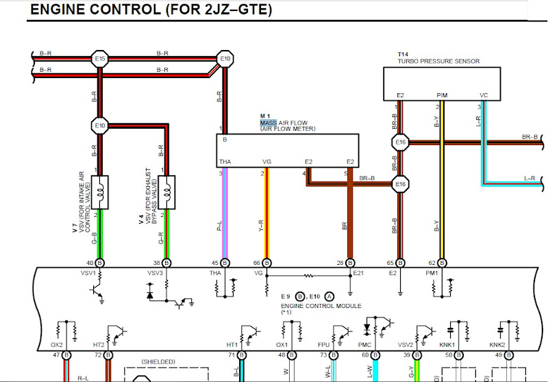
STEP 1: Install Map and IAT
Install Stock TT MAP sensor and IAT as per diagram below, if your wire colors are different go by pin location.
Map sensor can be 1jz or 2jz, thats about it. IAT can be from the 1jz, 2jz, GM, or a universal unit (im using an aem one).
If you want to run a piggyback like the map ecu, you can use that instead of the 1jz/2jz map sensor but note they are picky to setup initially.
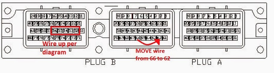
this is the wiring for the jdm ecu, which reuses all your old maf wires to connect your new map and IAT to. note you move the old maf signal wire pin (B66) to the map signal wire spot (B62) at the ecu plug do not forget or you will have no map signal
Just a heads up, when installing the map, get all your wires right and ready in the connector before plugging the map sensor in, if it isn't right unplug the map and do the wiring till you get it right. Don't make connections while the map is connected or you can hurt the map or worse the ecu 5V driver and then you could need a new ecu.
Step 2: Install injectors
stock TT size is 440cc, I suggest most people start here and it will support 400hp. good for at least a bar of boost on most medium size turbos. One member hit quite a bit over that on the dyno but not a bad idea to have a wideband and monitor your AFR's!!
Without a piggyback 550's will start and drive around but will run very rich and foul plugs eventually, 660cc won't run very well at all.
Most wash out the spark in boost when running 550's and no piggyback, so a piggyback is needed for 550cc+.
You are looking for top feed injectors (unlike gte side feed injectors), and you are looking for high impedance.
also they are specifically import size ("Denso") or 11mm, if you see domestic or 14mm injectors those will not fit the stock fuel rail.
7mgte injectors drop in but are low impedance and require a 7m or JZ resistor pack, and usually an injector cleaning.
Most aftermarket Denso 440cc's options are now high impedance and do not need a resistor pack, look for these.
Also there are alot of options online for re-manufactured injectors that seem to be a good route to try.
search for "2jzge injectors", I have used Oside tiger injectors and they seem to work really well as they rebuild oem injectors here in the US and quite a few members are running those now, watch out for other companies that do not rebuild oem ones and use knock off injectors, they generally do not idle or run properly and not actually flow matched (members here have actually tried them and not one has been successful so avoid these). Check the description before ordering, make sure they are actually Denso or Bosch units rebuild or re-manufactured.
Some injectors might have EV1 or EV14 connectors instead of the stock Denso clips, if that is the case you need to change your injector clips to that style (or use plug and play adapters). The adapters will make it longer for a FFIM which is good but connection now has an extra connector to worry about, other option is hardwiring which is more solid but takes more work, if rewiring make them longer so you can run a FFIM later without rewiring.
If you are 96+ or using a 96+ lower runner, note that the odb2 lower runner uses a different style of injectors. I don't recommend running this runner and you should swap to an obd1 lower runner and use obd1 injectors, you can also use a obd1 throttle body and that will get rid of the other size of the air assist hose.
Other good option would be to grab one of the newer FFIM's which has aftermarket runners and go FFIM if you have the engine bay space.
Step 3: Install Coil on plug ignition system
I recommend using the vvti coils and ignitor setup, which is all around better than gte coils and fits under the stock intake manifold.
See the diagram for the vvti wiring below.
You can run the vvti coils with either the lexus ignitor (DH61) or a toyota ignitor (DS62) as they both are the same ignitor.
I recommend finding the DS62 because they are widely available online and you can usually get the plug with some wires on it all for around ~$30, and the plug is really usefull as plug alone cost similar at toyota, and the dh61 alone will be several times more than this price and I have never seen one with the plug cause no one in their right mind will cut a vvti harness so you can have the plug and wires. You can get these parts at Toyota also if you have one without the plug but its pricey for just a connector and some wires.
I put steps 2 and 3 together, its because when doing the injectors you will have the stock intake manifold apart, and is a good time to drop the coils in as you will have to remove at least to the throttle body to get the vvti coils dropped in, like a regular spark plug change. Also the old metal spark plug holder thing needs to come out of the plug valley so your coilpacks can sit right and its held on by the inside valve cover bolts.
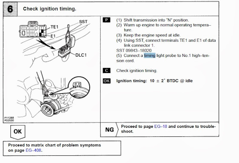
Step 4: Fire her up and set your base timing with a timing light.
Follow the timing check procedure in any of the manuals.
You jumper the diagnostic pins (TE1 and E1), and set the base timing by rotating the distributor.
You should always hear a VERY NOTICEABLE change in how the motor is running/sounding when you put the jumper in to set the base timing.
If you don't hear anything change, the tps is not in the right position and it wont let you change base timing cause it thinks you are revving some.
See this very helpful post by HiPSI showing how to adjust the tps when ecu won't let you set base timing. https://www.clublexus.com/forums/sc-...ml#post8524889
Once you got it changing sound when you put in the jumper, you are ready to initially set the base timing.
I recommend starting around 8 degrees, especially if you do not have a tt headgasket. If you do start out between 8-10 degrees.
After it is warmed up fully hot double check and adjust your base timing if necessary. If you set it cold before then it may be different now.
Play with the advance at your own risk but remember lower is safer but too low like 6 and under can cause other drive-ability issues.
Always set your base timing when changing ecu's, if you happen to be too advanced you can damage your motor
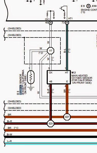
Step 5: O2 sensor
The stock o2 sensor technically will work the JDM ecu and you only need one o2 sensor instead of 2 or 3 you may have already.
some SC's / Supra's come with 1 wires sensors (non heated) and 4 wire sensors (heated- found on obd2 or all cali spec).
If you have a 4 wire then you have the right kind already, make sure the one that goes to ecu pin B48 is the one you are using, and that the heater for that one goes to B71.
If your downpipe doesn't take the bolt on kind you have you can just get a 4 wire sensor described below that is a scew in type, and redo the wiring on your plug, no need to add wires to the ecu since your car came with heated you are ahead of the curve.
If you have the 1 wire, you can use that temporarily and live with burning a little extra fuel on startup till the car warms... but you may have carbon fouling issues. I would get a 4 wire sensor and wire it up to the ecu. Alot of times you want a new sensor because of a screw in type for most downpipes and how sensitive these ecus are to the o2 feedback.
The sensor I use is a Denso 234-4309 universal 4 wire sensor (you can get great deals on these).
To wire a 1 wire to a 4 wire:
One black wire goes to ecu pin B71 (heater pin ecu uses to turn heater on).
Other black wire goes to 12v pin (black/red wire at ecu or in engine bay, power for the heater).
The White wire to a chassis ground (Its a ground don't ask me what its for just ground it already).
The blue wire goes to ecu pin B48 or just connect to original signal wire (note the signal wire is shielded, so peel back the shielding/stranded wire around the inside wire cause it is grounded. only connect to the inside wire, insulate it, then you can pull the shielding back over the connection as long as there is no electrical contact between them, look up connecting shielded wiring online).
This is what it looks like on a car that comes with a 4 wire o2 stock for reference (95 supra TT USDM).
Note that the heater wire on the JDM ecu is B71 as said above. It is not the one in the picture below the one below is just an example.
Step 6: A/C Relay (when using Aristo ecu, Supra ecu not needed).
If you are using an aristo ecu here is the a/c fix, see post #29
Basically GE Hvac unit sends send ground to the ecu, and aristo ecu wants a power signal, so this relay fixes that by sending power to the aristo ecu when it gets the ground from the GE Hvac unit. https://www.clublexus.com/forums/per...problem-2.html
Picture is gone but the diagram is on post #70 still (Thanks Gerrb) https://www.clublexus.com/forums/per...ml#post9149617
Step 7: torque converter lockup fix (Only for automatic models, if you are manual skip this step)
There was a theoretical relay fix here on post 1619 that was tried but it does not work, so don't expect this function to work.
I would suggest swapping to a manual transmission and not worrying about any of this stuff as mainly the stock auto is delicate and wont hold any decent power anyways so plan to move on from the stock auto when you go na-t. If you don't it won't last that long and you will have to do it right after it breaks anyways.
You can go with a GTE auto (if you want a built auto this route makes alot more sense) and add all the extra wiring (I don't know what exactly you will have to look up the wires I think its just a couple of plugs from ecu to transmission, or easier way is grab a gte harness and unwrap it and borrow all those wires).
Step 8: Re-Plumb ACIS butterfly directly to intake manifold (recommended with stock intake manifold)
The TT ecu has different VSV's than the GE ecu and does not control ACIS correctly when doing the mod.
This results in sluggish spool and down low performance basically getting no benefit from the GE intake manifold design.
Good news is connecting the ACIS valve as shown in the post below will give you a large increase in spool compared to leaving it disconnected.
In vacuum you get long runners all the time now for extra torque/spool, and when you get into boost it goes to short runner which is better for top end HP (when the engine needs the most air it can pull through both sides of the Y in short runner as opposed to one side in long runner).
Think of it like a car having long runners all the time, and short runners in boost. the end result is very good for performance.
see post 1095 https://www.clublexus.com/forums/8095725-post1095.html
If you have removed all those hardlines, simply run a vac line from intake manifold to the butterfly like you would connect a bov or boost gauge.
Connecting the 2 hardpipes shown above achieves that by bypassing the canister and connecting the butterfly to the intake directly.
Step 9: Tach mod to get tachometer reading again with new ignitor
the 3 channel (vvti) and 6 channel (gte) ignitors put out a different tach signal than the stock 1 channel ignitor (distributor).
to get it working again remove the cluster and you need to jump a resistor with a short piece of wire (bypassing it).
easiest is to just solder each side of the wire to each of the legs of the resistor going into the board (you don't have to remove resistor in case you ever want to go back just cut wire).
its the same thing you would do if you were doing a gte swap. These are for the SC, supra probably different resistors: jump the R109 resistor on 92-94 clusters, and the R73 resistor on 95-96 clusters. for the newer gauge clusters 97 .. jump resistor R2 (Thanks for the info Gerrb!)
Step 10: go out and actually enjoy your na-t for a change without battling the stock ecu
I have tested it out personally, and it runs great.
cheap engine management for 400hp with the 440cc injectors, basically how a stock supra drives with a single on it.
throw on a piggyback and larger injectors after you get it all sorted and you can make even more power.
The best part with na-t is that the distributor can be rotated, so you can actually change your base timing with the gte ecu.
This mod runs really well with the stock map sensor and 440cc injectors which is a great baseline to start from.
The gte ecu with proper coils should now be the starting point for na-t management, the ge ecu doesn't even come close driving wise.
My car drives like a stock lexus again, with about double the power.
I also wanted to add that this mod works great for a reliable driver that doesn't go too far away from the recipe.
As in once you get to too large of injectors and piggybacks and giant turbo or attempting to run E85 you will find it has certain limitations and it won't work well anymore.
So really use it for what it is, which is a good reliable way to reach bpu power levels with a good sized single.
Once you get above that power level you will want/need features standalone have to support those power levels properly etc..
Short vid of it running on the GTE coils and Ignitor, before I installed the vvti coils and ignitor.
Note: if you do not have a front facing intake manifold (FFIM), you cannot run TT coils and ignitor, they wont fit under the stock intake.
This is another reason I only recommend the vvti coils now.
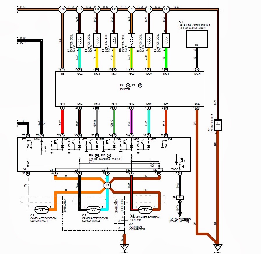
Here is what the ecu connector looks like and the places of interest to us (GE and GTE have same connector).
This shows how you wire up the coils and also move the wire for the old maf sensor to the new MAP sensor spot (ODB1 only).
Remember the 3 coils have to go in a certain order as shown in the picture (this is the least confusing arrangement trust me):
Coil 1 sits on cylinder 6 (and has a lead wire running to cylinder 1 not shown)
Coil 3 sits on cylinder 4 (and has a lead wire running to cylinder 3 not shown)
Coil 2 sits on cylinder 2 (and has a lead wire running to cylinder 5 not shown)
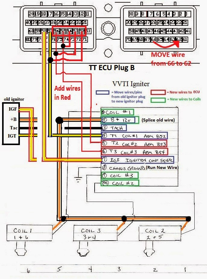
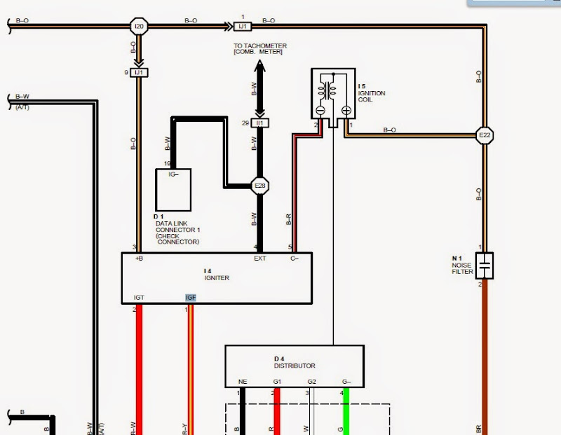
general guideline of what to do for the ignitor wiring:
your wire colors may be different but the pin locations are always the same on these ignitors.
look at this diagram from a 95 supra for pin locations (I don't have the SC one right now).
the power wire is usually black/orange or black/white, and the IGF is usually red/yellow... the tach wire can be black or random colors..
the rest well the vary from year to year, and they can even vary on the ones listed above depending on the chassis.
First remove all the pins/wires out from the old ignitor plug, and then insert them into the new ds62 ignitor plug as shown in the diagram, this includes +B, tach, IGT1, IGF.
you only run 2 new wires from the ecu and that is IGT2 and IGT3.
Then you add a ground wire and ground it to chassis ground or even battery ground.
For the 4 wires to the coils, you run the 3 signal wires (coils 1-3) to the new coils, and for the +B for the coil you have to splice off the +B wire you just moved over from the old ignitor.
The old coil wire that goes from the stock ignitor to the stock coil is not shown in the diagram above because normally its not used as it goes to the wrong place, but its the 5th wire connected to the old ignitor that's not the 4 shown above.
If you are planning to rewire your harness, or willing to unwrap the harness from the stock coil location back up to the distributor area you can reuse the coil power wire and the trigger wire for coil 1 (IGT1).
If you are not comfortable unwrapping/rewiring, you can just add all new wiring from ignitor to coils and splice into the power wire at the ignitor (or use a relay).
You can either just get 3 coilpack connectors and wiring and go at it, or an alternative is to buy a mk3 coilpack harness and extend the wires, as it has most of the right connectors but I think it will probably be short (haven't done it but have had several sets of mk3 coilpacks so familiar with them).
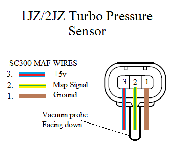
here is the wiring of the plug for the TT map sensor (courtesy of 8052JZ)
this is the wire description for the maf plug on the diagram below.
pin 1 is brown: Sensor ground for MAP and IAT (not to be confused with a regular ground. 5V sensors have their own ground pin on the ecu)
pin 2 is yellow/black: IAT signal wire
pin 3 is yellow/green: MAF/MAP signal (remember to move pin to b62 for JDM version of the mod)
pin 4 is blue/red : +5v (blue/red is always +5v not to be confused with +12v used on the newer maf's like the gte maf)
pin 5 is brown: another ground (I generally use the other ground above and leave this one alone)
im in the process of wiring up an aristo ecu, 2jzgte igniter, 7mgte coilpacks(doing wasted spark), and 7mgte CPS for my build, 2jzgte MAP sensor, 440cc injectors, and mk4 supra turbo denso fuel pump. basically doing na-t and making it think its running a stock 2jzgte jdm engine. i like tricking things
im in the process of wiring up an aristo ecu, 2jzgte igniter, 7mgte coilpacks(doing wasted spark), and 7mgte CPS for my build, 2jzgte MAP sensor, 440cc injectors, and mk4 supra turbo denso fuel pump. basically doing na-t and making it think its running a stock 2jzgte jdm engine. i like tricking things
Nice, good to see people giving it a shot. not sure if the gte ignitor can run wastespark coils but test it out.
*edit*
I had some issues running the cps on a TT ecu, so may want to stay away from that combo. The stock ecu uses 2 g signals (2 cam position sensors) and the distributor puts out the exact same signals. There is no difference in grounds between the cps and the dizzy for the 2 g signals (both have shared grounds). The TT ecu normally uses separate grounds for each of the sensors however this should not make much of a difference. you can use the stock distributor minus the cap and rotor. its just a little taller than a cps once you rip the guts out
These days I actually prefer the stock distributor over the CPS, but there is no short cap available for it yet, you have to make one yourself for the time being.
Stock coil usage (Requires DS62 ignitor)
The stock ignitor is not compatible with the gte ecu. the difference is the older ignitors returned an old style IGF signal to the ecu which it needs to stay running, and the newer coilpacks ecu's they changed the IGF to a current type signal so the engine starts and then dies.
What you do is replace the stock ignitor with the DS62 ignitor, and do not add the 2 new wires coming from the ecu.
You just pin up the old wires into the right spots on the new connector all for coil 1, so coil 2-3 and IGT 2-3 will be blank/unused on the new ignitor. Basically we are only using 1 channel of the 3 channels on the new ignitor, and it should work fine and return the right IGF to the ecu.
From Aaron's (aswilley) thread thanks for the updated diagram (do note he is using jdm ecu with stock coil on a 97 harness)
this shows the colors on a 97 harness which may look different than your or above. https://www.clublexus.com/forums/bui...ml#post9005400
USING THE USDM ECU
Alot of people have been asking about using the USDM ecu, especially when then are odb2 non-vvti it is usefull to use the USDM ecu so you can keep odb2 and all emissions in tact like a factory gte would, believe it or not the 2JZGE has the identical emissions components and sensors. You must use 550cc injectors, and Note the USDM ecu uses both a maf and map sensor
Here is how you wire that up for the USDM ecu on a 96-97 2JZGE harness.
wire up the coilpacks and ignitor as shown for the JDM ecu mod above. it is the same.
The stock maf sensor will be swapped with a TT unit, and the maf sensor plug will not be modified at all since 96-97 uses a hotwire 12V maf and the GTE maf is a 12v Hotwire maf with the exact same plug, do not cut the maf connector off like the JDM mod version above since its already plug and play. Since the USDM ecu uses both a maf and a map, we will run new wires for the map sensor since the maf is being kept. (Note for 96 harness users: on a 97 GE harness the maf ground wire 28 and is the same as a GTE pin, but it may be pin 30 on the 96 GE harness, so if you have a 96 you may have to move pin 30 to 28 for the maf to work correctly).
Just an update, for those using the US maf with a single turbo, it doesn't run that well until you delete the maf by using either a VPC or a map ecu type unit. its well documented on supraforums.
you can try the maf but I wont be helping troublshoot stuff that doesn't work right, plan to convert to map on the USDM ecu. its worth it if you have to keep obd2, otherwise just use a JDM ecu.
ultimately it should be a 2jz map sensor wired in for the US map sensor, and for the US maf sensor you have a map ecu or vpc wired to that.
so technically you have 2 map sensors, but the only one that is used for fueling on a US ecu is the one which was converted from being a maf.
For the Map sensor you run a new signal wire from the ecu from B62 to the map sensor signal on the connector and for the power and ground for the MAP sensor you can tap into the TPS power and special sensor ground, the TPS and MAP sensor power wires are the same blue/red color wire on all the harnesses this is the ecu 5V wire. Do not try to tap the power off the maf wires for the Map sensor as the maf is 12v and will not work on the map sensor, could even mess it up. Do not try and use the ground of the maf as this is a 12v or standard ground the map sensor uses the special sensor ground, again tps sensor is easiest place to pick up the power and ground for these then you only need to run 1 wire to the engine bay to the map sensor. This is my recommended method.
Refer to Aaron's 97 build thread that shows a new diagram for wiring the map sensor to the IAT for 96+ models.
Do note he used a JDM ecu but his diagram still shows the wiring for the map sensor power and ground that is needed on 96+ harnesses.
If you are on US ecu, the map signal will likely be running a new wire for the map signal, not reusing 62 from the maf as the US still needs that wire. https://www.clublexus.com/forums/bui...ml#post9005400
Thanks again for the updated diagram!!
There is no separate IAT (air intake sensor) like the jdm ecu has, because on the US setup it is built into the maf (see wire for THA) it is already wired so you can skip over IAT related stuff.
USING GTE COILS INSTEAD OF VVTI COILS (MUST HAVE FRONT FACING INTAKE MANIFOLD)
I would use the vvti coil setup above, but if you need to use sequential coils or just the regular gte coils, here is the stock wiring for the TT coilpacks. Again note: THEY DO NOT FIT UNDER THE STOCK GE INTAKE. YOU MUST HAVE A FFIM.
This time you will need to run 5 new wires instead of just the 2 needed for vvti coils, and just like above you reuse 57 and 58 (IGT1 and IGF) from the old ignitor as they are already there stock so you are just adding 52-56 and running to TT ignitor.
USING 1ZZ/2ZZ COILS INSTEAD OF VVTI COILS (MUST HAVE FRONT FACING INTAKE MANIFOLD)
You wire them like the gte coils above, except the wires from the ecu go straight to the coils skipping the ignitor.
Each coil will one also get its own power wire and ground wire since they have internal ignitors.
Each coil returns its own IGF signal, so you must connect all 6 wires together and feed them back to the 1 stock IGF wire to keep the engine happy and running.
USING LQ9 COILS (MUST HAVE FRONT FACING INTAKE MANIFOLD & Requires IGF Simulator)
You wire them like the gte coils above, except the wires from the ecu go straight to the coils skipping the ignitor.
Each coil will one also get its own power wire and ground wire since they have internal ignitors.
The GM coils do not return an IGF signal to the ecu, so to keep the engine running you will need an IGF Simulator/faker or find some way to keep the factory ignitor in the mix. If you know of another method that works let me know.
Aren't there more things you have to have in order to use this ECU? like 440cc injectors?
It's right at the very top but ill quote it for ya
Originally Posted by Ali SC3
Parts:
TT ecu: Jdm or US
injectors: 440cc (JDM) or 550cc (US)
airflow: TT Map(2.3 bar) + Iat (JDM) or TT maf (US)
Heated o2 sensors and maybe a few others just for cel's.
<<<<<<<<<
this guy is retared!!!!
I'm really not sure why I didn't realize that's what you were saying. I was thinking it was telling you how the ECU's came.....lol just misunderstood my bad!
We have regular 1 wire (non heated) o2 sensors (unless you have a lucky cali spec).
TT ecu's use heated o2 sensors which have 2-4 wires depending on the year/where it was produced. so its easiest to just order o2 sensors for the specific car your ecu came from.
some people like to just use the regular o2 sensors and just wire in resistors to "simulate" the heater circuit so the ecu doesn't throw any codes. its simple and it works, but you have 2 really hot resistors you have to deal with mounting now.
I feel its easiest to get new sensors and run the 2 extra wires for them to the ecu (straight shot through firewall), its easy to do and you get new sensors, which is all around better than reusing a tired old sensor on a performance car.
Im bumping this up cause I just ordered my GTE ecu, I will keep everyone posted on the progress once I get the ecu in, and start the conversion. Just need to find the IAT sensor. What resistor is needed to simulate the heater circuit? And what pin #'s do the IAT and MAP sensor wire to? The last pictures is kinda small and I cant see it..
I'm uploading a zoomed in pic of the original.
the map sensor signal is 62B
the IAT signal is 45B
the maf signal is 66B (you can just move this pin to 62B @ the ecu and connect the map signal to the old maf signal wire)
I just cut my old maf connector off and made a new connector using those wires for my map and Iat sensor. If you do it this way then there is no need to run new map+Iat wires to the ecu at all.
 04-02-10, 05:21 PM