Attn Soarer Members, Wiring Diagram Needed
 12-27-05, 10:23 PM
#1
Pole Position
Thread Starter
Join Date: Jan 2005
Location: Nightmare on Elm St.
Posts: 291
Likes: 0
Received 0 Likes
on
0 Posts
Bought Soarer folding mirror set from eBay- 2 mirrors, 1 mirror ECU relay, 1 master control switch:
http://cgi.ebay.com/ebaymotors/JDM-T...spagenameZWDVW
The unit was cut from the main wiring harness for the master control switch and the mirror ECU, so the wires are in a complete mess.
There are no diagrams included of course, and my US manual is useless here, so I am wondering who over in Austarlia has the wiring diagrams for the Master Control Switch and Mirror ECU?
Can you post them here to help me out.
 12-27-05, 11:19 PM
#2
Keeper of the light
iTrader: (17)
Why aren't you asking the guy's in australia? www.planetsoarer.com
Most of the guy's here are SE and Cali. (of course we get our spread of yorkies also)
Most of the guy's here are SE and Cali. (of course we get our spread of yorkies also
)
12-27-05, 11:29 PM
#3
Driver School Candidate

Join Date: Dec 2005
Location: TX
Posts: 14
Likes: 0
Received 0 Likes
on
0 Posts
12-28-05, 03:34 AM
#4
Originally Posted by Davidss
this is off the glass....thanks!
12-28-05, 07:48 AM
#5
Hey buddy,
Looks like there is another ECU you may need a different brain module and controller than we have. I will check the schematics for the US model when I get home tonight, however based on the diagrams at the link above there is an entirely seperate 'piggyback' unit.
If that is the case then without the module/controller this will not work as I am sure there is some logic (like a PWM signal) to driving the 'shaker'.
Peter
12-28-05, 05:11 PM
#6
Pole Position
Thread Starter
Join Date: Jan 2005
Location: Nightmare on Elm St.
Posts: 291
Likes: 0
Received 0 Likes
on
0 Posts
Originally Posted by 933005spd
Hey buddy,
Looks like there is another ECU you may need a different brain module and controller than we have. I will check the schematics for the US model when I get home tonight, however based on the diagrams at the link above there is an entirely seperate 'piggyback' unit.
If that is the case then without the module/controller this will not work as I am sure there is some logic (like a PWM signal) to driving the 'shaker'.
Peter
Looks like there is another ECU you may need a different brain module and controller than we have. I will check the schematics for the US model when I get home tonight, however based on the diagrams at the link above there is an entirely seperate 'piggyback' unit.
If that is the case then without the module/controller this will not work as I am sure there is some logic (like a PWM signal) to driving the 'shaker'.
Peter
The package actually came with a Japanese Mirror ECU for the 92 Soarer.
So I have the master control switch (with the additional fold button), 2 mirrors with heat sensors etc.., and a full J-Spec mirror ECU cut from the main harness.
In summation, I complete wiring mess


I have to do my homework, and ascertain the schematics for each of the following for the US Version, then for the Soarer version.
My thought is that side-by-side, I could "pre-wire" the Mirror ECU implant on paper, before heading straight to the practical application.
The way I see it right now, I am not sure if I will have to add the J-Spec Mirror ECU in addition to the US ECU. The J-Spec to control folding, mirror shake- the US to control other features (defrost, rotation, etc).
Or I might be able to use just the J-Spec ECU for all of it together.
Let me know what you think Peter....

But first things first, please PM me the US diagrams before I go chasing down the Soarer diagrams...
12-28-05, 05:13 PM
#7
Pole Position
Thread Starter
Join Date: Jan 2005
Location: Nightmare on Elm St.
Posts: 291
Likes: 0
Received 0 Likes
on
0 Posts
Originally Posted by Davidss
Awesome link. Thanks!!! I downloaded them all
Trending Topics
12-28-05, 07:13 PM
#8
Ok, I am trying to make sense of these and it will take some work. I am very interested....
If you look at the schematic for the 93 SC400 w/ Driving position memory you will note that each motor has an H and a V listed.....
I belive this is for the horizontal and vertical position sensors for the position memory.
Do you know if the JDM version has position memory?
P
If you look at the schematic for the 93 SC400 w/ Driving position memory you will note that each motor has an H and a V listed.....
I belive this is for the horizontal and vertical position sensors for the position memory.
Do you know if the JDM version has position memory?
P
12-28-05, 08:37 PM
#9
Pole Position
Thread Starter
Join Date: Jan 2005
Location: Nightmare on Elm St.
Posts: 291
Likes: 0
Received 0 Likes
on
0 Posts
I do not know if the JDM ECU has Driver Position Memory....my guess would be not because it did not have heated mirrors...not sure on that.
I decided it was by time to upload a few pictures of the ECU wires and plugs, and the Master Control buttons...


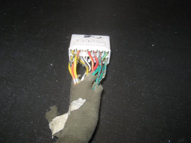


I decided it was by time to upload a few pictures of the ECU wires and plugs, and the Master Control buttons...
12-28-05, 08:47 PM
#10
Pole Position
Thread Starter
Join Date: Jan 2005
Location: Nightmare on Elm St.
Posts: 291
Likes: 0
Received 0 Likes
on
0 Posts
Peter,
On that diagram you provided, the right portion seems to be dedicated to switching polarity.
Since the folding motors work on a simple 2 wire (ground) (pos +) setup then the motors move one way (depending on how you wired them- only in OR only out.
If you switch the POS and NEG leads then they will move in the opposite direction. The mirrors needs to move in when prompted, then REVERSE charge to move back out. Switching polarity.
A nightmare to do without the ECU, but possible.
The ECU also reads 2 additional wires on each mirror that tells the ECU when the mirror is FULLY extended and FULLY in AND to please cut Power.
If power is not cut, then the mirrors will over extend 10 or so degrees then try to continuously move in that direction.
Basically, the ECU is everything in this setup.
The master control switch (besides mirror shake) should be a simple in line switch.
HOWEVER, my question is:
1) Why is it tied into the Tilt ECU?
2) Why is in tied into the Dome light?
What purpose does this serve?
I think I will install the minium I need on the J-Spec Mirror ECU for it to function and use it in sync with the US version.
What do you think?
12-29-05, 08:22 AM
#11
Ok, so I have taken a look at some more schematics - look at the link referenced above, go to Soarer Diagrams, Section 3 PDF pg. 8 and pg. 9.
I belive your system is similar to the one on pg 9 (3-33 in the upper right side). This is also very similar to the 'remote control mirrors' schematic we have been looking at. This shows some relays and diodes inside.
Are you handy with a VOM? I would check some of the mirror wires to see if there is continuity on certain pins when folded in or out. This will help identify the position sensors (if any?).
I belive, but not certain, that this mirror also will heat up. In our SC FSM there are some test procedures using low voltage - this is worth a try to id some of the pins also.
Have you checked the existing connectors on the door lock/unlock window portion of that switch? Is it Plug n Play?
Your thought of using the the stock ECU along with this one for the fold/shake functions should be possible - however.....
I belive that you will loose the memory function on the mirror. Also, I am not sure if taking the mirror out of the loop will somehow affect the logic for the other components (seats, steering). It is worth testing this by simply disconnecting the mirrors.
You asked why it is tied into the Tilt & Telescopic ECU. This is because the mirror position is part of that driving position memory.
The dome light tie is is most likely to supply a constant 12v to the mirror ECU and subsequently to the Tilt and Telescopic ECU for memory functions.
If you do find there is continuity among the mirror pins when folded in/out then you should be able to very simply use some 12v automotive relays for both reversing voltage and for cutting off voltage. If you need some relay pointers to do this I can help you out, or check out the12volt.com
Really cool function, I hope you get this working.
Peter

Thread
Thread Starter
Forum
Replies
Last Post
nkostaki
GX - 1st Gen (2004-2009)
5
10-18-10 11:12 AM
LS007
Lexus Audio, Video, Security & Electronics
2
11-05-01 09:55 PM