IS300 Fans - How to wire them
 08-11-14, 03:40 PM
#1

Good day gents
I want to install a set of is300 fans with my setup. Im on a aem and would like the aem to control fans
wiring is not my thing persay, so im asking for help here from someone who has done this before.
What i would like is both fans in series on low speed , once temp rises say 15 degrees above then both kick on in series at high speed and of constant high speed with ac on.
I need to know how to wire in relay and how and what wire to pin to aem
 08-12-14, 05:02 AM
#2

Lex - you won't be able to run them at high speed in series. They have to be in parallel for them to be on high speed. Reason why they run low speed when in series is the 12 volts is divided by the two fans ... but when they are in parallel, they both receive same 12v so they run faster (high speed) though more current (AMPS)
The switching between low speed and high speed is accomplished by 3 relays and how they are wired. The AEM basically provides the grounding to turn on the relays based on what temperature it sees through the coolant temperature sensor or whatever condition parameters you will enable on the AEM .
I will try to draw up a sketch for you on how to wire them not unless someone around here has one ready to post..
08-12-14, 05:51 AM
#3
Lex - you won't be able to run them at high speed in series. They have to be in parallel for them to be on high speed. Reason why they run low speed when in series is the 12 volts is divided by the two fans ... but when they are in parallel, they both receive same 12v so they run faster (high speed) though more current (AMPS)
The switching between low speed and high speed is accomplished by 3 relays and how they are wired. The AEM basically provides the grounding to turn on the relays based on what temperature it sees through the coolant temperature sensor or whatever condition parameters you will enable on the AEM .
I will try to draw up a sketch for you on how to wire them not unless someone around here has one ready to post..
The switching between low speed and high speed is accomplished by 3 relays and how they are wired. The AEM basically provides the grounding to turn on the relays based on what temperature it sees through the coolant temperature sensor or whatever condition parameters you will enable on the AEM .
I will try to draw up a sketch for you on how to wire them not unless someone around here has one ready to post..
gerrb , i thank you for taking the time to post .. wiring guru , i am not .. i can hold my own once i fully understand the concept
what i would like the fans to do if possible is have low speed run in series . one come on when temps say reach 150 , second at low speed above say 165 , then both run in parallel at high speed say above 180 and high speed with ac on ..
i sincerely would appreciate if you could post up a clear diagram and what wire goes to the aem ( i already know what pin to pin on aem) just need to know what wire to send to aem ..
08-12-14, 07:41 AM
#4
Let me first show you what I did on my Black Mamba with two IS300 fans. It is a lot simpler , less wiring and less components...only 3 relays to take care of the switching from low speed to high speed . If you really want the setup you mentioned above , I can draw up a wiring plan for you.
Here is a sketch of my IS300 fans wiring diagram I quickly did just to show how mine are wired. I will do a good explanation on how it will work on any ECU on my next post.
Got to run and get some fuel for my riding mower so I can cut the grass before my neighbors start complaining.

Last edited by gerrb; 08-12-14 at 11:14 AM.
08-12-14, 07:42 AM
#5
With the above diagram ,
A) You should have at least one relay that should have 5 pins (2 for pin 85 & 86 which is the relay coil , 30 is for common and would be used for the voltage supply , 87a is the normally closed pin , 87 is the normally open pin ) , for the other two relays you can used a 4 pin relay ( those relays do not have the 87a which is the Normally Close pin ) or it doesn't hurt to use 5 pin relays for all the three.
b) Connect AEM Wire 1 to any available LOW Side (these connects the wire to ground to complete the circuit where as HIGH SIDE provides +voltage) switching output of your ECU... in this case your AEM.
c) Enable that switch on the AEM and set the parameters / conditions when you want it to toggle the switch to ON. Like , you want the AEM lets say to toggle that switch to ON when it sees Coolant TEMP at 160. You can add other parameters available there.. There are around 5 conditions you can set. You can set the condition also when to toggle it OFF based on whatever temperature you want.
NOTE: DO NOT set those ON & OFF temperatures so near each other , otherwise your fans will be cycling on & off like crazy and will never transition back to LOW SPEED... I would say at least 5-10 degrees in between the ON & OFF settings.
d) Once your ecu sees that all conditions are met .. it toggles that LOW SIDE switch to ON thereby grounding that AEM Wire 1
e) With AEM Wire 1 grounded , it energizes the coil of Relay 2 , thus the internal switch of Relay 2 is activated. And following the diagram , voltage is supplied from pin 30 of Relay 2 to Fan 1 and also to Fan 2 since the diagram shows that they are in series.
f) Being in series , there would be voltage drop for each fan , basically like dividing the +12 volts into two (6v for each fan) that is why they run at a lower speed.
g) Now for AEM Wire 2 , again set the condition you want, let's say 178... again once that condition is met , Relay 1 and Relay 3 are energized . Because of the switching we did through how we wired the relays , each fan now has his own +12v supply , thus they are running faster (HIGH SPEED).
NOTE : I would personally set the HIGH Speed Conditions at a higher temperature like 190 on my end. The less they go on High Speed , better cause those fans at high speed uses huge amount of current and if your alternator is not able to return it to your battery , it will kill that battery especially at night when all the lights are on too. Since you are using a TRD 160 thermostat where the coolant is brought back to the radiator to be cooled, you may not even see them go on high speed depending on the conditions you set. Just experiment what is the best TEMP settings to turn them ON and OFF on your particular setup.
Also make sure that if AEM Wire 2 is switched to ON , AEM Wire 1 is also ON. Theoretically it should cause the conditions of your AEM Wire 1 is at a lower temperature so it is still ON at the moment AEM Wire 2 is switched to ON , otherwise only the fan on the right of the diagram will be running. So be careful in setting your ON/OFF conditions for both AEM wire 1 & 2.
Don't worry about the AC. Even if your AC is ON all the time or not , your fans are controlled by what temperature your ECU sees. IF you set your high speed ON condition to 178 , then regardless whether your AC is on or off , those fans will be on HIGH SPEED the moment that ECU senses your engine is going hot (above your preset condition)
As for which of the two wires on the plug of the fans you will use , it will now depend on which pin number each of the two fan motor wires were connected. This is what you can do, once it is all setup , you will need to make sure that the fans are sucking air out of the radiator rather than pushing air towards the radiator. Just reverse the wiring on the plug of the fan if they are not sucking air. You won't damage the fan if those wires are inverted. The fan will just rotate on the opposite direction (reverse) ... a fan is made up of a big coil of wire so there is no polarity per se.
NOTE : The relays can all have a common switched/fused +12 volts supply. The same with the fans. Just be aware of the size of wires you use on the fans, they draw a lot of amperage.
Last edited by gerrb; 08-12-14 at 02:00 PM.
The following users liked this post:
KiroLS (09-21-20)
08-12-14, 09:22 AM
#6
Thx for the diagram, last question. Each fan has a 2 wire plug which of the two do I use in your diagram. Running the 2 at low speeds is fine. I guess I could have them turn on via aem at say 160 then run high speeds once temp reaches say 178 and go back to low speeds at say 165. How do I activate high speedswhen ac is on all the time
08-12-14, 09:28 AM
#7
Thx for the diagram, last question. Each fan has a 2 wire plug which of the two do I use in your diagram. Running the 2 at low speeds is fine. I guess I could have them turn on via aem at say 160 then run high speeds once temp reaches say 178 and go back to low speeds at say 165. How do I activate high speeds when ac is on all the time
Trending Topics
08-14-14, 04:21 AM
#10
With the above diagram ,
A) You should have at least one relay that should have 5 pins (2 for pin 85 & 86 which is the relay coil , 30 is for common and would be used for the voltage supply , 87a is the normally closed pin , 87 is the normally open pin ) , for the other two relays you can used a 4 pin relay ( those relays do not have the 87a which is the Normally Close pin ) or it doesn't hurt to use 5 pin relays for all the three.
b) Connect AEM Wire 1 to any available LOW Side (these connects the wire to ground to complete the circuit where as HIGH SIDE provides +voltage) switching output of your ECU... in this case your AEM.
c) Enable that switch on the AEM and set the parameters / conditions when you want it to toggle the switch to ON. Like , you want the AEM lets say to toggle that switch to ON when it sees Coolant TEMP at 160. You can add other parameters available there.. There are around 5 conditions you can set. You can set the condition also when to toggle it OFF based on whatever temperature you want.
NOTE: DO NOT set those ON & OFF temperatures so near each other , otherwise your fans will be cycling on & off like crazy and will never transition back to LOW SPEED... I would say at least 5-10 degrees in between the ON & OFF settings.
d) Once your ecu sees that all conditions are met .. it toggles that LOW SIDE switch to ON thereby grounding that AEM Wire 1
e) With AEM Wire 1 grounded , it energizes the coil of Relay 2 , thus the internal switch of Relay 2 is activated. And following the diagram , voltage is supplied from pin 30 of Relay 2 to Fan 1 and also to Fan 2 since the diagram shows that they are in series.
f) Being in series , there would be voltage drop for each fan , basically like dividing the +12 volts into two (6v for each fan) that is why they run at a lower speed.
g) Now for AEM Wire 2 , again set the condition you want, let's say 178... again once that condition is met , Relay 1 and Relay 3 are energized . Because of the switching we did through how we wired the relays , each fan now has his own +12v supply , thus they are running faster (HIGH SPEED).
NOTE : I would personally set the HIGH Speed Conditions at a higher temperature like 190 on my end. The less they go on High Speed , better cause those fans at high speed uses huge amount of current and if your alternator is not able to return it to your battery , it will kill that battery especially at night when all the lights are on too. Since you are using a TRD 160 thermostat where the coolant is brought back to the radiator to be cooled, you may not even see them go on high speed depending on the conditions you set. Just experiment what is the best TEMP settings to turn them ON and OFF on your particular setup.
Also make sure that if AEM Wire 2 is switched to ON , AEM Wire 1 is also ON. Theoretically it should cause the conditions of your AEM Wire 1 is at a lower temperature so it is still ON at the moment AEM Wire 2 is switched to ON , otherwise only the fan on the right of the diagram will be running. So be careful in setting your ON/OFF conditions for both AEM wire 1 & 2.
Don't worry about the AC. Even if your AC is ON all the time or not , your fans are controlled by what temperature your ECU sees. IF you set your high speed ON condition to 178 , then regardless whether your AC is on or off , those fans will be on HIGH SPEED the moment that ECU senses your engine is going hot (above your preset condition)
As for which of the two wires on the plug of the fans you will use , it will now depend on which pin number each of the two fan motor wires were connected. This is what you can do, once it is all setup , you will need to make sure that the fans are sucking air out of the radiator rather than pushing air towards the radiator. Just reverse the wiring on the plug of the fan if they are not sucking air. You won't damage the fan if those wires are inverted. The fan will just rotate on the opposite direction (reverse) ... a fan is made up of a big coil of wire so there is no polarity per se.
NOTE : The relays can all have a common switched/fused +12 volts supply. The same with the fans. Just be aware of the size of wires you use on the fans, they draw a lot of amperage.
A) You should have at least one relay that should have 5 pins (2 for pin 85 & 86 which is the relay coil , 30 is for common and would be used for the voltage supply , 87a is the normally closed pin , 87 is the normally open pin ) , for the other two relays you can used a 4 pin relay ( those relays do not have the 87a which is the Normally Close pin ) or it doesn't hurt to use 5 pin relays for all the three.
b) Connect AEM Wire 1 to any available LOW Side (these connects the wire to ground to complete the circuit where as HIGH SIDE provides +voltage) switching output of your ECU... in this case your AEM.
c) Enable that switch on the AEM and set the parameters / conditions when you want it to toggle the switch to ON. Like , you want the AEM lets say to toggle that switch to ON when it sees Coolant TEMP at 160. You can add other parameters available there.. There are around 5 conditions you can set. You can set the condition also when to toggle it OFF based on whatever temperature you want.
NOTE: DO NOT set those ON & OFF temperatures so near each other , otherwise your fans will be cycling on & off like crazy and will never transition back to LOW SPEED... I would say at least 5-10 degrees in between the ON & OFF settings.
d) Once your ecu sees that all conditions are met .. it toggles that LOW SIDE switch to ON thereby grounding that AEM Wire 1
e) With AEM Wire 1 grounded , it energizes the coil of Relay 2 , thus the internal switch of Relay 2 is activated. And following the diagram , voltage is supplied from pin 30 of Relay 2 to Fan 1 and also to Fan 2 since the diagram shows that they are in series.
f) Being in series , there would be voltage drop for each fan , basically like dividing the +12 volts into two (6v for each fan) that is why they run at a lower speed.
g) Now for AEM Wire 2 , again set the condition you want, let's say 178... again once that condition is met , Relay 1 and Relay 3 are energized . Because of the switching we did through how we wired the relays , each fan now has his own +12v supply , thus they are running faster (HIGH SPEED).
NOTE : I would personally set the HIGH Speed Conditions at a higher temperature like 190 on my end. The less they go on High Speed , better cause those fans at high speed uses huge amount of current and if your alternator is not able to return it to your battery , it will kill that battery especially at night when all the lights are on too. Since you are using a TRD 160 thermostat where the coolant is brought back to the radiator to be cooled, you may not even see them go on high speed depending on the conditions you set. Just experiment what is the best TEMP settings to turn them ON and OFF on your particular setup.
Also make sure that if AEM Wire 2 is switched to ON , AEM Wire 1 is also ON. Theoretically it should cause the conditions of your AEM Wire 1 is at a lower temperature so it is still ON at the moment AEM Wire 2 is switched to ON , otherwise only the fan on the right of the diagram will be running. So be careful in setting your ON/OFF conditions for both AEM wire 1 & 2.
Don't worry about the AC. Even if your AC is ON all the time or not , your fans are controlled by what temperature your ECU sees. IF you set your high speed ON condition to 178 , then regardless whether your AC is on or off , those fans will be on HIGH SPEED the moment that ECU senses your engine is going hot (above your preset condition)
As for which of the two wires on the plug of the fans you will use , it will now depend on which pin number each of the two fan motor wires were connected. This is what you can do, once it is all setup , you will need to make sure that the fans are sucking air out of the radiator rather than pushing air towards the radiator. Just reverse the wiring on the plug of the fan if they are not sucking air. You won't damage the fan if those wires are inverted. The fan will just rotate on the opposite direction (reverse) ... a fan is made up of a big coil of wire so there is no polarity per se.
NOTE : The relays can all have a common switched/fused +12 volts supply. The same with the fans. Just be aware of the size of wires you use on the fans, they draw a lot of amperage.
08-14-14, 08:16 AM
#11
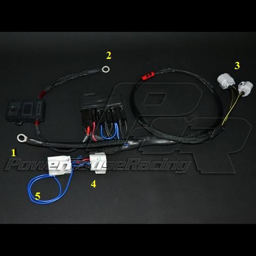
The PHR pre made harness , looking at their website picture , this is my guess on how it operates with that tapping on the EB1 connector. On that connector , they get the power to energize the relays. It is on EB1 that the AC magnetic relay is also turned on. So once the AC compressor is on , you just have to activate the other relays and fans go high speed. Though with the blue wire on the picture below, they have the option of energizing the relays through an ECU also. But I believe they are using a HIGH SIDE ecu output switch (one that provides voltage).
Since I see only 3 relays and no high wattage resistors (not unless my eyes are deceiving me) both fans operate at the same time at low speed or high speed.
This is the way how that works :
Since their harness is tapped from the EB1 connector , one relay is energized by a pin from EB1 to get the fans running in low speed (fan in series -> voltage drop of 6v per fan), then when the AC magnetic clutch is activated whose wire passes through EB1 also , it powers up the other two relays that enables the two fans to run parallel (getting the complete 12v) thus they run in HIGH SPEED when AC compressor is running. Switching from LOW SPEED (fans in series ) and HIGH SPEED (fans in parallel) is accomplished by HOW those three relays are wired.

I personally would prefer the fans being controlled by the ECU and not whether the AC compressor is ON or OFF. Why ? My AC might be off and my engine is overheating because the fans are not going high speed ( just because my AC magnetic clutch fan is off ...which does the triggering of the relays to get the fans in high speed) .
Last edited by gerrb; 08-14-14 at 09:49 AM.
08-14-14, 09:10 AM
#12
For those who are not on stand alone ECUs and want to use the IS300 electric fans and want to control their operation based on temperature monitoring of the engine coolant , here is what you can do..
Get two Coolant Temperature Switches from NAPA or anywhere. Most radiators have two ports at the bottom to screw on these coolant temp switches. Get one lets say that closes at 160F for Coolant Temp Sensor 1 and another sensor that closes at 190F. for Coolant Temp Sensor 2.
Note that such sensors also have closing temp and opening temp meaning, the switch closes at a particular temperature and opens up again at a lower temperature so check those numbers based on what temperature you want the fans to operate.
Here is the wiring diagram.. instead of the standalone ECU (AEM above) , you have coolant temperature switches ...operates exactly the same way based on coolant temperature.
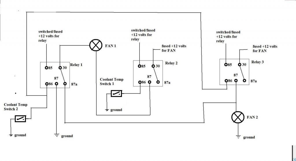
 08-14-14, 09:45 AM
#13
Gerrb , according to their website here's a excerpt from the website talking about how it works and what it can do
Supra 6 Speed***PHR PNP Harness for IS300 Fan KitItem #:PHR 01010714Price:$305.00Sale Price:$295.00Quantity:**OverviewRelated ProductsReviewsOur PNP Harness for our IS300 Fan Kit.**available here*Simplify the wiring on your dual fan setup. Run you fans on LOW or HIGH. High activates with the Air conditioning as well as on command using the "High input" wire.Works on any dual fan setup.We use only the highest grade components and wiring in all of our wire harness products.*
Supra 6 Speed***PHR PNP Harness for IS300 Fan KitItem #:PHR 01010714Price:$305.00Sale Price:$295.00Quantity:**OverviewRelated ProductsReviewsOur PNP Harness for our IS300 Fan Kit.**available here*Simplify the wiring on your dual fan setup. Run you fans on LOW or HIGH. High activates with the Air conditioning as well as on command using the "High input" wire.Works on any dual fan setup.We use only the highest grade components and wiring in all of our wire harness products.*
08-14-14, 10:13 AM
#14
Gerrb , according to their website here's a excerpt from the website talking about how it works and what it can do
Supra 6 Speed***PHR PNP Harness for IS300 Fan KitItem #:PHR 01010714Price:$305.00Sale Price:$295.00Quantity:**OverviewRelated ProductsReviewsOur PNP Harness for our IS300 Fan Kit.**available here*Simplify the wiring on your dual fan setup. Run you fans on LOW or HIGH. High activates with the Air conditioning as well as on command using the "High input" wire.Works on any dual fan setup.We use only the highest grade components and wiring in all of our wire harness products.*
Supra 6 Speed***PHR PNP Harness for IS300 Fan KitItem #:PHR 01010714Price:$305.00Sale Price:$295.00Quantity:**OverviewRelated ProductsReviewsOur PNP Harness for our IS300 Fan Kit.**available here*Simplify the wiring on your dual fan setup. Run you fans on LOW or HIGH. High activates with the Air conditioning as well as on command using the "High input" wire.Works on any dual fan setup.We use only the highest grade components and wiring in all of our wire harness products.*
a) the blue wire can be connected on the ECU using a HIGH SIDE wire (one that provides voltage) to energize the relays and get the fan on high speed.
b) looking at the harness picture , those fans work at the same time.. either SLOW or FAST... Slow all the time and they trigger them to FAST when the AC magnetic clutch is on OR by triggering the relays from the ECU.
The difference in our circuit above is,
a) we use the ECU low side switches
b) I believe ( I might be wrong here since I have never seen their harness) looking at the wires on the EB1 connector and since they only have one blue wire to the ECU, in their harness both fans are always running slow the moment the car's ignition is on whereas we activate the slow speed of fans or they only turn on only when our temperature goes 160F
c) On their end, fans go to FAST speed when AC is on OR the ECU switch is ON (that is if that blue wire goes to the ECU and parameters set) ... and on our end fans get into the FAST SPEED when temperature is 190F or above (based on what we set the AEM Wire 2 on the first diagram above)
If you want that wiring schema ... we can do that too. It is just that, my $0.02 is, it should not matter whether the AC is on or not, the moment my ECU sees that my engine is getting hot , it should turn the fans in LOW speed (based on my low speed ECU switch settings) and then HIGH speed ( based on my high speed ECU switch settings).
If I am getting this all right , assuming that the HIGH speed is not triggered on by an ECU (for those not on standalone) , the problem I see on controlling the FAST SPEED by checking ONLY whether the AC is on is -> fans never go FAST SPEED if AC is off ? (since the relays for high speed are only on when magnetic clutch is on ? ) ... this is all my personal interpretation based on the components and wires I see on that harness in that picture.
When I have time I will draw a wiring diagram of how I believe that PHR harness works based on what I see on that picture (with wires tapped on the EB1 connector and one wire for ECU output switch, 3 relays , fuse box with fuse of course ). I wish we have someone who has that harness and tell us what wire is connected to what wire on that EB1 tapping so we know exactly how their harness operates. But I have a pretty good idea how it works based on what I see on their picture.
Last edited by gerrb; 08-14-14 at 12:44 PM.
08-14-14, 02:21 PM
#15
Assumption -> The PHR pre made harness for the IS300 fans can be used on the MKIV and SC300
After having evaluated the MKIV and SC300 wiring diagrams and just by looking at their harness picture and seeing what components they have used , this is how I believe that harness is wired. I said "I believe" because I have never seen one in person nor have I asked anyone what wires are connected to which wire NOR do I claim that this is the way it is definitely wired.
Picture 1 -> their harness with point of connections numbered
I believe this is the schematic diagram of their harness, I have place encircled numbers on the diagram so you know where that goes in relation to the PHR harness picture.
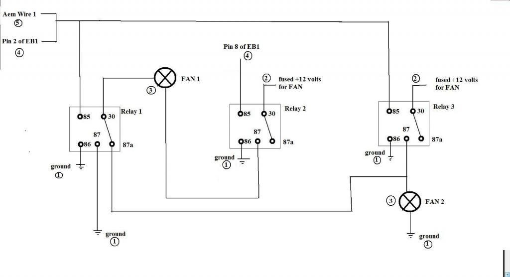
Pin 85 of Relay 2 is connected to Pin 8 of EB1 (SC300) or Pin 8 of EA1(MKIV) which is for the Main Relay. So once the ignition switch is on , Relay 2 is activated (given voltage through that pin) thereby turning the relay switch to ON and the 2 fans ON at LOW SPEED (being in series).
They have two ways of turning them to HIGH SPEED
a) ECU switch (based on preset temperature ) using HIGH SIDE meaning it provides voltage to the RELAY
b) Pin 85 of Relay 1 and Relay 3 is connected to PIN 2 of EB1(SC300) or Pin 2 of EA1(MKIV) which is the relay to activate the AC Magnetic Clutch. Thus when the AC compressor is on, power flows to Relay 1 and Relay 3 activating their internal switches which consequently provide individual 12v to each fan so they ran at high speed
As what we have done in our first wiring diagram, switching from LOW SPEED to HIGH SPEED is accomplished by how the 3 relays are wired.
Just my $0.02
After having evaluated the MKIV and SC300 wiring diagrams and just by looking at their harness picture and seeing what components they have used , this is how I believe that harness is wired. I said "I believe" because I have never seen one in person nor have I asked anyone what wires are connected to which wire NOR do I claim that this is the way it is definitely wired.
Picture 1 -> their harness with point of connections numbered

I believe this is the schematic diagram of their harness, I have place encircled numbers on the diagram so you know where that goes in relation to the PHR harness picture.

Pin 85 of Relay 2 is connected to Pin 8 of EB1 (SC300) or Pin 8 of EA1(MKIV) which is for the Main Relay. So once the ignition switch is on , Relay 2 is activated (given voltage through that pin) thereby turning the relay switch to ON and the 2 fans ON at LOW SPEED (being in series).
They have two ways of turning them to HIGH SPEED
a) ECU switch (based on preset temperature ) using HIGH SIDE meaning it provides voltage to the RELAY
b) Pin 85 of Relay 1 and Relay 3 is connected to PIN 2 of EB1(SC300) or Pin 2 of EA1(MKIV) which is the relay to activate the AC Magnetic Clutch. Thus when the AC compressor is on, power flows to Relay 1 and Relay 3 activating their internal switches which consequently provide individual 12v to each fan so they ran at high speed
As what we have done in our first wiring diagram, switching from LOW SPEED to HIGH SPEED is accomplished by how the 3 relays are wired.
Just my $0.02
Last edited by gerrb; 08-14-14 at 02:41 PM.

