IS300 Fans - How to wire them
 08-15-14, 03:30 AM
#16

Ed - Bryan's answer to your question on their section at SF basically confirms our diagram above.. which is how their harness is wired.
There you go , at least you now have choices how to wire yours whichever way you think will be best for your setup.
There you go , at least you now have choices how to wire yours whichever way you think will be best for your setup.
 08-15-14, 04:43 AM
#17

maybe my 60 hr work weeks has melted my brain :egads , so their harness WILL allow me to have both fans on at low speed WITH the ability of my aem to determine when they turn on and also allow me to determine via aem at what temp they trigger on for high speed and of course will automatically trigger on high with ac on
08-15-14, 07:06 AM
#18
maybe my 60 hr work weeks has melted my brain :egads , so their harness WILL allow me to have both fans on at low speed WITH the ability of my aem to determine when they turn on and also allow me to determine via aem at what temp they trigger on for high speed and of course will automatically trigger on high with ac on
With that kind of wiring , No , the low speed of both fans cannot be controlled by the AEM because they only have one wire for the AEM switch which is used only to trigger them to high speed.
The way they did it is (and for which how my last diagram works) , the moment you turn your ignigtion switch to on , the fans are on low speed right away because Relay 2 is powered through Pin 8 of EB1 (SC300) or Pin 8 of EA1(MKIV)
So when does the fans go high speed on their wiring ?
a) what ever temperature you set on your AEM , that is assuming you have connected that blue wire to a HIGH Side AEM switch which gives powers relay 1 and relay 2
OR
b) whenever the AC magnetic clutch is ON since they tapped the power of relay 1 and relay 2 to PIN 2 of EB1(SC300) or Pin 2 of EA1(MKIV)
Note :
1) You have no control of when the fans turn on at low speed, they automatically are on as long as the ignition switch is on because of how they tapped the power of Relay 2 from the EB1 connector.
2) Remember you got to use a High Side AEM switch (provides +voltage) for their kind of harness diagram. My first diagram on this thread uses Low Side switches of the AEM ( provides grounding only).
Last edited by gerrb; 08-15-14 at 07:29 AM.
08-15-14, 08:17 AM
#20
Driver School Candidate

Join Date: Aug 2014
Location: TX
Posts: 1
Likes: 0
Received 0 Likes
on
0 Posts
This is a very interesting read.
My fan harness is a very simple device. But there are a couple keys missing in the whole discussion.
gerrb you are on the money on the concept except the trigger from the ECU.
Also another key point, and I can't state this enough: the amount of time and effort it takes to build your own setup makes the PHR harness a BARGAIN! Trust me when I say that. We don't make money on our harness when we factor in my time and looming, and sourcing connectors and terminals etc. etc etc. The only reason we build it is for customers who lack the knowledge to do it themselves and we want too make the wiring of our dual is300 fan kits as seamless as possible for the end customer.
Lexforlife - good luck on your project. hope it works good for you, but trust me when I say it's not worth the time. Hit me up if you want to buy ours, I can give you a good deal.
Thanks,
Bryan @ PHR
817-238-8434
Last edited by TopGunSC; 08-15-14 at 08:21 AM.
08-15-14, 10:30 AM
#21
This is a very interesting read.
My fan harness is a very simple device. But there are a couple keys missing in the whole discussion.
gerrb you are on the money on the concept except the trigger from the ECU.
Also another key point, and I can't state this enough: the amount of time and effort it takes to build your own setup makes the PHR harness a BARGAIN! Trust me when I say that. We don't make money on our harness when we factor in my time and looming, and sourcing connectors and terminals etc. etc etc. The only reason we build it is for customers who lack the knowledge to do it themselves and we want too make the wiring of our dual is300 fan kits as seamless as possible for the end customer.
Lexforlife - good luck on your project. hope it works good for you, but trust me when I say it's not worth the time. Hit me up if you want to buy ours, I can give you a good deal.
Thanks,
Bryan @ PHR
817-238-8434
My fan harness is a very simple device. But there are a couple keys missing in the whole discussion.
gerrb you are on the money on the concept except the trigger from the ECU.
Also another key point, and I can't state this enough: the amount of time and effort it takes to build your own setup makes the PHR harness a BARGAIN! Trust me when I say that. We don't make money on our harness when we factor in my time and looming, and sourcing connectors and terminals etc. etc etc. The only reason we build it is for customers who lack the knowledge to do it themselves and we want too make the wiring of our dual is300 fan kits as seamless as possible for the end customer.
Lexforlife - good luck on your project. hope it works good for you, but trust me when I say it's not worth the time. Hit me up if you want to buy ours, I can give you a good deal.
Thanks,
Bryan @ PHR
817-238-8434
Bryan - I really appreciate the input , thanks. Since I have never seen one of your harness , I just tried to decipher how it works based on the components , terminals , connectors and wires I see on the picture and what had been said about the blue wire being used to toggle the fans into high speed mode and having tapped some wires on the EB1 connector for SC300s & EA1 connector for MKIVs...... so I can do my share of helping people . Though there are lots of ways to modify the last wiring diagram just to make it work exactly that of PHR.
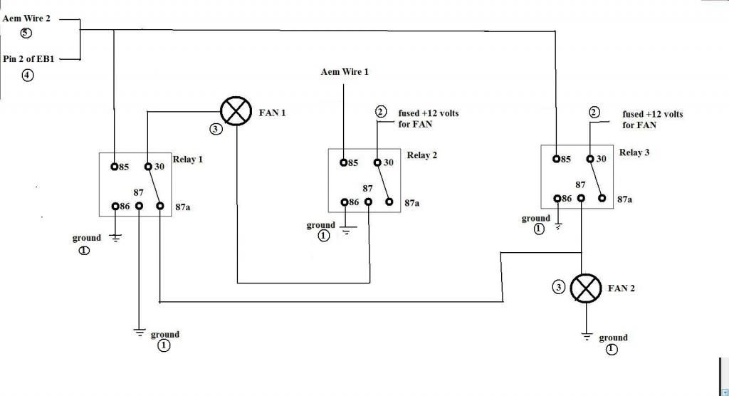
* AEM Wire 1 would be connected to a HIGH SIDE ECU Output switch to activate relay 2. You set the conditions / parameters on your ECU like what temp you want the switch to turn ON and OFF . When conditions are met , it will get the fans in LOW SPEED mode. The temp settings here should be lower than the temp settings of AEM Wire 2
How will the fans go into HIGH SPEED then ?
1) AEM Wire 2 would be connected to a HIGH SIDE ECU Output switch to activate relay 1 & 3 . You set the conditions / parameters on your ECU like what temp you want the switch to turn ON and OFF. When conditions are met , it will get the fans in HIGH SPEED mode. Your temp settings here should be higher than the temp settings of AEM Wire 1
OR
2) Then tap the other wire numbered 4 on the diagram to PIN 2 of EB1(SC300) or Pin 2 of EA1(MKIV) which should get the fans into HIGH SPEED whenever the AC compressor is ON.
NOTE : Let me emphasize it , you will be using 2 x HIGH SIDE output switches from your AEM ECU for which you will be providing power to relay coils. On our very first diagram , we were just providing ground using LOW SIDE output switches from the ECU.
MY PERSONA:L VIEW ($0.02)
I know when you turn on the AC , more heat is produced at the engine bay which in turn makes the engine hot . That is why you can turn the fans into HIGH SPEED when the AC Compressor / Magnetic Clutch is ON. But for me, that is exactly what the AEM Wire 2 output switch will do .. as soon as it senses your engine getting hotter than your preset temp / condition , it activates the switch to On and gets the FANS into HIGH SPEED.
I believe the EB1 tapped wires for turning on the fans (first to low speed then high speed when AC is ON) where meant for those NOT using a stand alone. It is redundant for those with standalones.
In fact , in my case , if I don't have a standalone ECU to switch ON the AEM Wire 1 & 2 on the diagram , I would rather use 2 Coolant Temp Switches (with the right switching temperatures) bolted into the radiator (most rads have 2 NPT ports anyway) as in one of my previous diagrams to monitor the ACTUAL temperature of the engine rather than tying the operation of fan's HIGH SPEED with the AC compressor operation. Why will I get the fans into high speed mode,,,, just because the AC is ON ? What if my AC is not on like during winter ? I will rather get the fan in HIGH SPEED mode when TRULLY my engine is hotter than my preset temperature as it is being monitored by the coolant switches or by the ECU . Those fans in HIGH SPEED mode draws quite an amount of current... so if I can turn them into high speed mode ONLY when it is necessary ....then that will be better .
Exactly I guess the same reason why you are asking for control for the low speed mode for the fans through the ECU , so they turn ON only when necessary , at a preset temperature or conditions.
Just my $0.02.
Here is a hybrid wiring diagram ..simple modification from the previous diagram :

Last edited by gerrb; 08-15-14 at 12:53 PM.
08-16-14, 10:40 AM
#22
Bryan - I really appreciate the input , thanks. Since I have never seen one of your harness , I just tried to decipher how it works based on the components , terminals , connectors and wires I see on the picture and what had been said about the blue wire being used to toggle the fans into high speed mode and having tapped some wires on the EB1 connector for SC300s & EA1 connector for MKIVs...... so I can do my share of helping people . Though there are lots of ways to modify the last wiring diagram just to make it work exactly that of PHR.
YES , here you go (it will be a hybrid of our first and last diagram of this thread)
* AEM Wire 1 would be connected to a HIGH SIDE ECU Output switch to activate relay 2. You set the conditions / parameters on your ECU like what temp you want the switch to turn ON and OFF . When conditions are met , it will get the fans in LOW SPEED mode. The temp settings here should be lower than the temp settings of AEM Wire 2
How will the fans go into HIGH SPEED then ?
1) AEM Wire 2 would be connected to a HIGH SIDE ECU Output switch to activate relay 1 & 3 . You set the conditions / parameters on your ECU like what temp you want the switch to turn ON and OFF. When conditions are met , it will get the fans in HIGH SPEED mode. Your temp settings here should be higher than the temp settings of AEM Wire 1
OR
2) Then tap the other wire numbered 4 on the diagram to PIN 2 of EB1(SC300) or Pin 2 of EA1(MKIV) which should get the fans into HIGH SPEED whenever the AC compressor is ON.
NOTE : Let me emphasize it , you will be using 2 x HIGH SIDE output switches from your AEM ECU for which you will be providing power to relay coils. On our very first diagram , we were just providing ground using LOW SIDE output switches from the ECU.
MY PERSONA:L VIEW ($0.02)
I know when you turn on the AC , more heat is produced at the engine bay which in turn makes the engine hot . That is why you can turn the fans into HIGH SPEED when the AC Compressor / Magnetic Clutch is ON. But for me, that is exactly what the AEM Wire 2 output switch will do .. as soon as it senses your engine getting hotter than your preset temp / condition , it activates the switch to On and gets the FANS into HIGH SPEED.
I believe the EB1 tapped wires for turning on the fans (first to low speed then high speed when AC is ON) where meant for those NOT using a stand alone. It is redundant for those with standalones.
In fact , in my case , if I don't have a standalone ECU to switch ON the AEM Wire 1 & 2 on the diagram , I would rather use 2 Coolant Temp Switches (with the right switching temperatures) bolted into the radiator (most rads have 2 NPT ports anyway) as in one of my previous diagrams to monitor the ACTUAL temperature of the engine rather than tying the operation of fan's HIGH SPEED with the AC compressor operation. Why will I get the fans into high speed mode,,,, just because the AC is ON ? What if my AC is not on like during winter ? I will rather get the fan in HIGH SPEED mode when TRULLY my engine is hotter than my preset temperature as it is being monitored by the coolant switches or by the ECU . Those fans in HIGH SPEED mode draws quite an amount of current... so if I can turn them into high speed mode ONLY when it is necessary ....then that will be better .
Exactly I guess the same reason why you are asking for control for the low speed mode for the fans through the ECU , so they turn ON only when necessary , at a preset temperature or conditions.
Just my $0.02.
Here is a hybrid wiring diagram ..simple modification from the previous diagram :
08-16-14, 03:31 PM
#23
There you go ,that is the diagram you need if you want to control when to turn fans at low speed which I don't think that of the PHR design has since I firmly believe they turn on at low speed once ignition is on. I base that judgement on the fact that there is only one wire for their ECU option which I believe is another way of turning the fans to high speed as they themselves said it I believe. Just take note ,you have to use high side AEM switches.
If I were you man, just do the first diagram of this thread. It is simpler . That tapping from the EB1 / EA1 connectors are more for those not using stand alones. AC ON monitoring to turn the fans into high speed is in my personal opinion inferior to monitoring ACTUAL engine temperatures. During winter that AC compressor never will turn on . Ooooops .. I forgot you are there down south.... maybe for you yes.
Well, it is unfortunate that you have been misunderstood. Hopefully things will clear up and be better.
Good Luck . Store my number... faster to communicate through phone.
12-06-14, 05:33 PM
#24
Driver School Candidate

Join Date: Mar 2014
Location: Ky
Posts: 29
Likes: 0
Received 0 Likes
on
0 Posts
Bumping an old thread, but has anyone had any luck wiring them up like gerrb's diagram using a stock ecu? What coolant temp senders did you use? Thanks for your help
09-16-15, 01:37 PM
#25
soardrft - bumping this thread for you . Post #12 is the diagram you should follow for your IS300 fans we were discussing through PMs
get two coolant temp sensors . Radiators usually have two holes to bolt in sensors. One would have a higher temp rating so fans would turn on in high speed. The lower temp rating sensor just turns them in low speed. Make sure the on and off temp characteristics of each sensor are not so near each other otherwise fans will be cycling on and off the whole time. A difference of 10 degrees for the on and off temp characteristics should be fine.
get two coolant temp sensors . Radiators usually have two holes to bolt in sensors. One would have a higher temp rating so fans would turn on in high speed. The lower temp rating sensor just turns them in low speed. Make sure the on and off temp characteristics of each sensor are not so near each other otherwise fans will be cycling on and off the whole time. A difference of 10 degrees for the on and off temp characteristics should be fine.
09-16-15, 02:02 PM
#26
Lead Lap
iTrader: (8)

Join Date: Jan 2005
Location: ca
Posts: 468
Likes: 0
Received 0 Likes
on
0 Posts
Gerrb,
I have a megan racing supra radiator
http://www.meganracing.com/products/...d=736&catid=68
I show there is only 1 port for a temp switch. is it possible to connect the low side to my ignition and my fans are on at start up while the temp switch activates the high side?
I have a megan racing supra radiator
http://www.meganracing.com/products/...d=736&catid=68
I show there is only 1 port for a temp switch. is it possible to connect the low side to my ignition and my fans are on at start up while the temp switch activates the high side?
 09-16-15, 06:09 PM
#27
Gerrb,
I have a megan racing supra radiator
http://www.meganracing.com/products/...d=736&catid=68
I show there is only 1 port for a temp switch. is it possible to connect the low side to my ignition and my fans are on at start up while the temp switch activates the high side?
Attachment 369953
I have a megan racing supra radiator
http://www.meganracing.com/products/...d=736&catid=68
I show there is only 1 port for a temp switch. is it possible to connect the low side to my ignition and my fans are on at start up while the temp switch activates the high side?
Attachment 369953
The moment you turn the key to on though , both fans are on low speed right away and when the temp sensor switch reaches goes on , they will be on high speed.
difference with 2 temp switch is no fan is on if not necessary ...
04-12-17, 05:22 PM
#30
First, thank you for these awesome diagrams and discussion!
Now my problem: I wired up per this diagram. I connected the two signal wires for testing purposes to a 12v source and found a problem. If I connect "AEM wire 2" to 12v, one of the fans turns on at high speeds. When I connect "AEM wire 1" alone, then both fans run at low speed. When I connect BOTH wires to 12v, then only that first fan will run but runs at low speed. I'm looking over the diagram and I don't think I messed anything up but I'm not ever getting both fans at high speed.
Now my problem: I wired up per this diagram. I connected the two signal wires for testing purposes to a 12v source and found a problem. If I connect "AEM wire 2" to 12v, one of the fans turns on at high speeds. When I connect "AEM wire 1" alone, then both fans run at low speed. When I connect BOTH wires to 12v, then only that first fan will run but runs at low speed. I'm looking over the diagram and I don't think I messed anything up but I'm not ever getting both fans at high speed.