2JZGTE Wiring Harness Made Easy
 02-18-14, 05:42 PM
#121

did you try replacing the EFI relays ? If the switch portion of the relay is shorted , then there is continuous flow of electricity even after ignition is cut off .
The sequence is when you turn ignition, power is supplied to pin 1 (IGSW) of ECU which in turn gives power to the relay (M-Relay) pin 24 ... through EB1 pin 8 to the EFI relay. When switch is off , then power to that EFI relay is cut off... but apparently in your situation , current is still flowing. So I wonder if the relay is internally shorted on the switch side. This I am assuming , you had a good working harness before.
The sequence is when you turn ignition, power is supplied to pin 1 (IGSW) of ECU which in turn gives power to the relay (M-Relay) pin 24 ... through EB1 pin 8 to the EFI relay. When switch is off , then power to that EFI relay is cut off... but apparently in your situation , current is still flowing. So I wonder if the relay is internally shorted on the switch side. This I am assuming , you had a good working harness before.
 02-18-14, 06:03 PM
#122
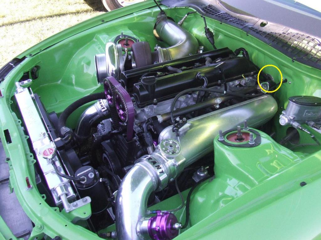
Today , I was doing a research on how to hide the 2jzgte harness wiring and doing a wire tuck on my Red Mamba 2 . Ali_SC3 pointed out that a hole is drilled on the firewall behind the engine for those shaving their engine bays or doing a wire tuck... just like pictured, observe what I encircled in yellow where the engine harness is brought into the cabin through that hole on the firewall.
This gave me a wild thought that probably can be explored by those doing a 2jzgte Wiring Harness. IF THERE IS A SPACE behind the center console / behind the radio where you can fasten the ECU and still can be accessed easily , THEN MAYBE, we can get away with not extending the Aristo Harness . The only wires that need to go to the right side panel on the passenger footwell are the body plugs anyway.
JUST A WILD THOUGHT that can be considered maybe. That helps save a lot of time and work . Imagine avoiding a lot of cutting, extending, soldering, shrink wrapping. You can build a 2jzgte wiring harness in no time.
This gave me a wild thought that probably can be explored by those doing a 2jzgte Wiring Harness. IF THERE IS A SPACE behind the center console / behind the radio where you can fasten the ECU and still can be accessed easily , THEN MAYBE, we can get away with not extending the Aristo Harness
. The only wires that need to go to the right side panel on the passenger footwell are the body plugs anyway.JUST A WILD THOUGHT that can be considered maybe. That helps save a lot of time and work . Imagine avoiding a lot of cutting, extending, soldering, shrink wrapping. You can build a 2jzgte wiring harness in no time.

Last edited by gerrb; 02-18-14 at 06:06 PM.
02-19-14, 12:28 PM
#123
Pole Position
iTrader: (6)
Join Date: Nov 2006
Location: PA
Posts: 276
Likes: 0
Received 0 Likes
on
0 Posts
The harness worked fine before. We are looking into the relay today. If the relay is ok ill look into the pin outs for the eb1
Thanks for the research we appreciate it!!
Thanks for the research we appreciate it!!
did you try replacing the EFI relays ? If the switch portion of the relay is shorted , then there is continuous flow of electricity even after ignition is cut off . The sequence is when you turn ignition, power is supplied to pin 1 (IGSW) of ECU which in turn gives power to the relay (M-Relay) pin 24 ... through EB1 pin 8 to the EFI relay. When switch is off , then power to that EFI relay is cut off... but apparently in your situation , current is still flowing. So I wonder if the relay is internally shorted on the switch side. This I am assuming , you had a good working harness before.
02-21-14, 08:37 AM
#125
You know my number, call me or text me if you have questions.
02-21-14, 10:45 AM
#126
Ryan, no I don't . What I will post there are supposed to be pictures of the finished harnesses. There is not much really to take pictures on that process. It will simply be one wire at a time being soldered / connected to the body plugs. If you look at the pictures on post 80, the way the two harnesses( aristo & sc300) are layed out, you just have to cut the wire going to the body plug and solder the corresponding wire you labeled from the Aristo (Charts you did are your guide now) . You should know by the chart which wire from the Aristo goes to which pin of a body plug. That is the reason I emphasized the charts and labeling of wires you take out from the big gray Aristo Plug so you know where to connect them.
You know my number, call me or text me if you have questions.
You know my number, call me or text me if you have questions.
02-25-14, 09:37 PM
#127
Hey man I just finished up on getting my SC300 harness ready to be merged...I consolidated your diagrams into to text....It was much easier for me to read and made a few corrections
Note: I have decided to remove my Diagnostic port not to over complicate the wiring
All plugs below have been verified per SC300 Wiring Diagrams
BODY PLUG CHART SC300 w/ W58
IK1 (Orange 23 Pin)
2 <--> AE7 (TE2)
3 <--> AF10 (VF1)
4 <--> AF4 (TE1)
5 <--> Pin 17 of the 40 pin ECU Connector
7 <--> Pin 1 of Noise Filter
8 <--> AF12(Tachometer Output from Igniter) <--> Pin 1 of 4 Pin Igniter Connector
9 <--> AF9 (Engine Coolant Temperature Dash Sensor)
11<--> (Re-use SC300 Reverse Plug)
20<--> AF8 (Low Oil Pressure Switch)
IK2 (White 25 Pin)
9 <--> AE2 (Check Engine Light)
10<--> AD1 (Low Oil Level Switch)
23 <-->Pin 3 of EB1
24 <-->Add to Front Intake Manifold Ground of GTE harness
IJ1 (Grey 14 Pin)
1 <--> AC15 (Fuel Pump Power Supply)
2 <--> Pin 2 of II1 & Pin 2 of Heater Valve Plug
4 <-->Pin 2 of the Horn Plug
5 <--> Pin 2 of the Alternator Connector
7 <--> AF6 (Ignitor Switch Power, Coils, Fuel Injector Input)<--> Pin 2 of 4 Pin Igniter Connector
8 <--> Pin 21 of the 40 pin ECU Connector (Fuel Pump ECU)
9 <-->Pin 1 of the Horn Plug
10<--> AE14 ( - Ignition Switched Power)
11<--> (Reuse SC300 Reverse Plug)
12<--> AE3 ( +B Main EFI Relay)
14 <-->Pin 22 of the 40 pin ECU Connector (Fuel Pump ECU)
II1(White 12 Pin)
1 <--> AC1 (AC -)
4 <--> AC2 (AC +)
1 <--> Pin 7 of the EB1 Connector
2 <--> Pin 2 of the IJ1 Connector & Pin 2 of Heater Valve Plug
4 <--> Pin 2 of the AC Connector
5 <--> Pin 34 of the 40 Pin Connector (AC Request Signal)
7 <--> Pin 1 of the Heater Valve Plug
Short - Not sure which plug this is?
4 <--> AE3 <--> Pin 2 of O2 sensor
EB1 (Black Fuse Plug 8 Pin)
1 <--> AC5 (AC Magnetic Clutch)
2 <-->Pin 23 of the 40 pin ECU Connector (AC Magnetic Clutch)
3 <-->Pin 23 of IK2 & to Pin 2 of the Park / Neutral Switch (& to Pin 8 of IJ2 (Manual Transmission Cars from Factory))
4 <--> Pin 33 of the 40 pin ECU Connector (Battery)
7 <--> AC1 (AC -)
8 <-->Pin 24 of the 40 pin ECU Connector (Main EFI Relay)
Pin 7 of EB1 goes to Pin 1 of the II1 Connector & to Pin 1 of the AC Connecto
EB2 (Black Fuse Plug 3 Pin)
1 <--> AE3 <--> AF1
2 <-->Pin 1 of the Alternator Connector
40 PIN ECU CONNECTOR
6 <--> AE2 (Check Engine Light)
7 <--> AE13 (REverse Light Plug)
19<--> AE7 (TE2)
20<--> AF4 (TE1)
31<--> AE3 (+B Main EFI Relay)
Alternator Connector
1 <-->Pin 2 of the EB2 Connector
2 <-->Pin 5 of the IJ1 Connector
3 <-->Pin 13 of the IJ2 Connector
IJ2 (Grey 17 Pin)
1 <-->Pin 64 of 80 pin ECU Connector (TPS Idle Sensor)
3 <-->Pin 2 of the 40 pin ECU Connector (No.1 Speed Sensor)
4 <-->Pin 11 of the 40 pin ECU Connector (Cruise Control)
6 <-->Pin 1 of PPS Solenoid (PS)
7 <-->Pin 4 of the 40 pin ECU Connector (Stop Light Switch)
8 <-->Pin 3 of EB1 (for manual transmission cars only)
10 <-->Pin 6 of IJ1 (for SC300)
11 <--> Pin 1 of the 40 pin ECU Connector (Ignition Switch)
13 <-->Pin 3 of the Alternator Connector
16 <-->Pin 2 of PPS Solenoid (PS)
SC300 Short Connector (White 6 Pin)
1 <-->Pin 8 of IK1 Connector
2 <-->Pin 20 of IK1
3 <-->Pin 3 of IJ1
4 <-->Pin 1 of EB2
5 <-->Pin 7 of IJ1
Pin 23 of IK2 to Pin 6 of IJ1....You need to do this or car will not start
Last edited by CatManD3W; 02-28-14 at 09:18 AM.
02-27-14, 02:58 AM
#128
Great .. remember some of the wiring to the body plugs are not all from the big gray Aristo plug. Going through all the diagrams over again helps you find every pin of a body plug that should have a connection. I might have missed some am sure while doing the writeup. But if you got the whole process of how to do it, you should be able to extract and verify every pin of the body plugs that should have a connection.
BTW , Ryan as I have mentioned to you on the phone.. having the Diagnostic port is just something nice to have but if it confuses the hell out of you, you don't really need to have it to get your car running. If you observe my Red Mamba I, I took out the Diagnostic Port and all the wiring associated with it to make it simple and cleaner. Am pretty sure , you are not bringing your car to a dealership where they will need the diagnostic port to connect their equipments to troubleshoot the car. It is not a stock engine for our SC anyway.
BTW , Ryan as I have mentioned to you on the phone.. having the Diagnostic port is just something nice to have but if it confuses the hell out of you, you don't really need to have it to get your car running. If you observe my Red Mamba I, I took out the Diagnostic Port and all the wiring associated with it to make it simple and cleaner. Am pretty sure , you are not bringing your car to a dealership where they will need the diagnostic port to connect their equipments to troubleshoot the car. It is not a stock engine for our SC anyway.
Last edited by gerrb; 02-27-14 at 03:07 AM.
02-27-14, 09:52 AM
#129
Great .. remember some of the wiring to the body plugs are not all from the big gray Aristo plug. Going through all the diagrams over again helps you find every pin of a body plug that should have a connection. I might have missed some am sure while doing the writeup. But if you got the whole process of how to do it, you should be able to extract and verify every pin of the body plugs that should have a connection.
BTW , Ryan as I have mentioned to you on the phone.. having the Diagnostic port is just something nice to have but if it confuses the hell out of you, you don't really need to have it to get your car running. If you observe my Red Mamba I, I took out the Diagnostic Port and all the wiring associated with it to make it simple and cleaner. Am pretty sure , you are not bringing your car to a dealership where they will need the diagnostic port to connect their equipments to troubleshoot the car. It is not a stock engine for our SC anyway.
BTW , Ryan as I have mentioned to you on the phone.. having the Diagnostic port is just something nice to have but if it confuses the hell out of you, you don't really need to have it to get your car running. If you observe my Red Mamba I, I took out the Diagnostic Port and all the wiring associated with it to make it simple and cleaner. Am pretty sure , you are not bringing your car to a dealership where they will need the diagnostic port to connect their equipments to troubleshoot the car. It is not a stock engine for our SC anyway.
03-28-14, 01:21 PM
#132

So I was looking at page 1 where it shows the portion of the harness for the auto connectors and the plugs, am I correct to assume then if the harness I have doesn't have those and instead has one 3 pin plug that I am looking at a manual harness and this 3 pin plug is for reverse lights or something?
For some crazy reason I just assumed all the auto stuff was on the body harness on auto cars but I can see how I was wrong about that (never had an auto harness) as it looks like all the auto stuff is all on the engine harness. Even I learned something.. I think, lol.
For some crazy reason I just assumed all the auto stuff was on the body harness on auto cars but I can see how I was wrong about that (never had an auto harness) as it looks like all the auto stuff is all on the engine harness. Even I learned something.. I think, lol.
03-29-14, 06:27 AM
#133
So I was looking at page 1 where it shows the portion of the harness for the auto connectors and the plugs, am I correct to assume then if the harness I have doesn't have those and instead has one 3 pin plug that I am looking at a manual harness and this 3 pin plug is for reverse lights or something?
For some crazy reason I just assumed all the auto stuff was on the body harness on auto cars but I can see how I was wrong about that (never had an auto harness) as it looks like all the auto stuff is all on the engine harness. Even I learned something.. I think, lol.
For some crazy reason I just assumed all the auto stuff was on the body harness on auto cars but I can see how I was wrong about that (never had an auto harness) as it looks like all the auto stuff is all on the engine harness. Even I learned something.. I think, lol.
 . Nobody was born with all the knowledge.
Manual tranny SCs will have the reverse light plug or maybe if modified also a speed sensor plug (for the tach I believe) on that area. If it is an auto then all those plugs should also be on the engine harness since a lot of those wiring have to go to the ECU so it can be controlled.
04-10-14, 12:04 PM
#134
Was trying to help someone trace the problem on the 2jzgte harness he built since his car wouldn't start . Checking on the harness , this is one of the mistakes so I am posting it here so others would be aware of it . If you get your pin numbering wrong , then you will be connecting wires on the wrong pins.
Q) How do you know which are the pin numbering of plugs that has slots and pins that are neither on the first or second row ... they are between just like pictured ?
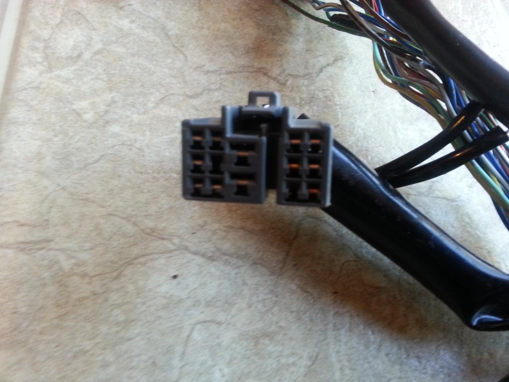
Usually , you will read it belonging to the next row .. like the first big pin at the center of the picture is not pin 3 , it will be pin 7
05-02-14, 06:56 AM
#135
I just wanted to inform other CL members that I have used this thread along with the provided SC300 wiring diagrams and I have a running and driving car....If you follow this thread like I did make a chart like Gerrb suggested.....It helps out alot when you are going back over the harness to double check that all wires are going to correct plugs etc...
THIS IS BY FAR THE BEST THREAD I HAVE EVER SEEN.....YOU THE MAN GERRB....Thanks
THIS IS BY FAR THE BEST THREAD I HAVE EVER SEEN.....YOU THE MAN GERRB....Thanks