2JZGTE Wiring Harness Made Easy
#76
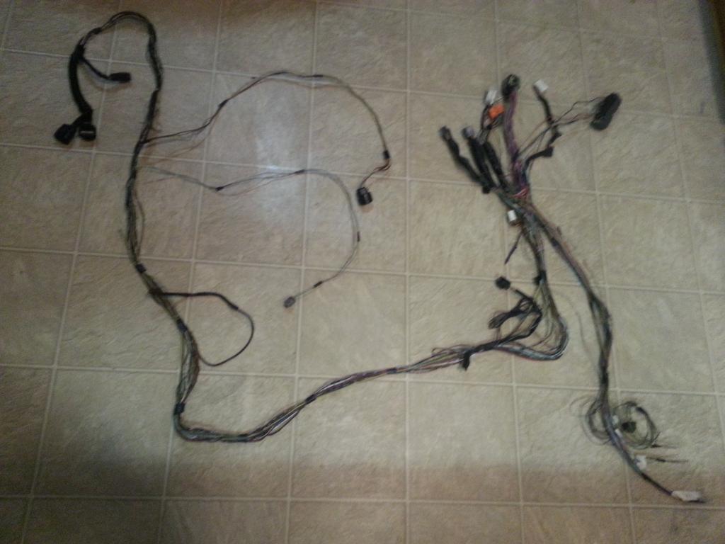
Nothing much here except overlay wires / plugs to be merged
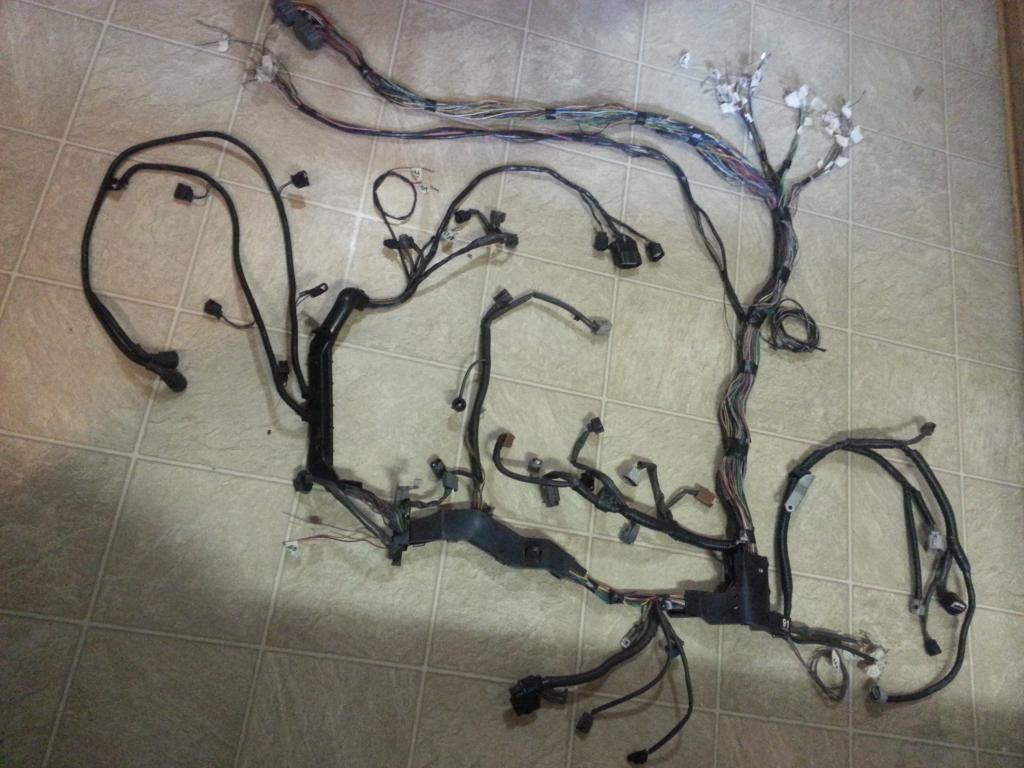

Most of my extra wires are near the auto transmission plugs . I have around 14 on that area... plain and simple ...sucker for extra wires
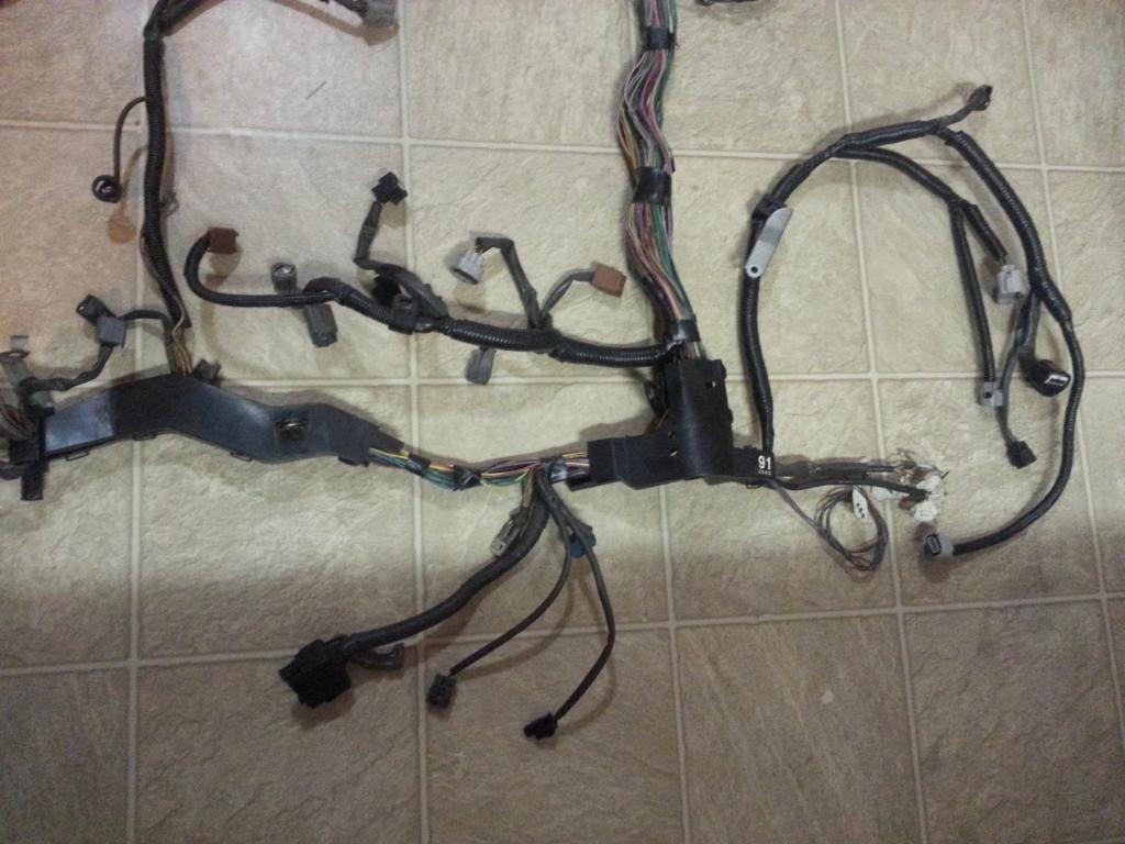
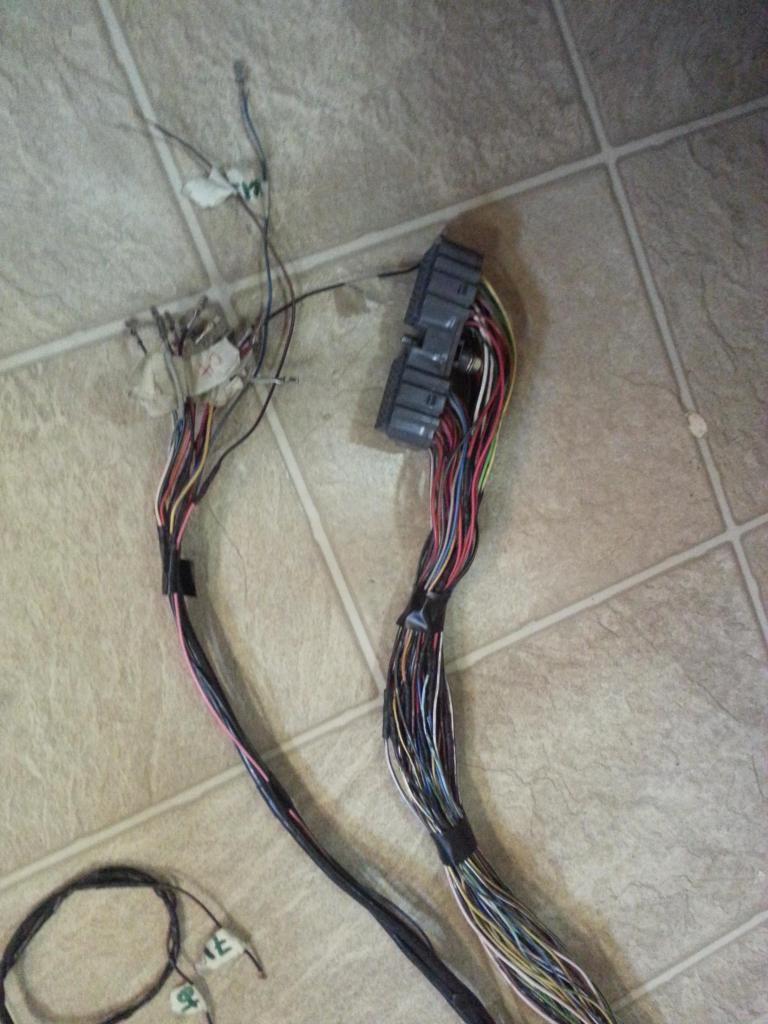
Extra wires and the 80 pin ECU connector. All these wires have already been extended.
This is the area where all the merging will happen
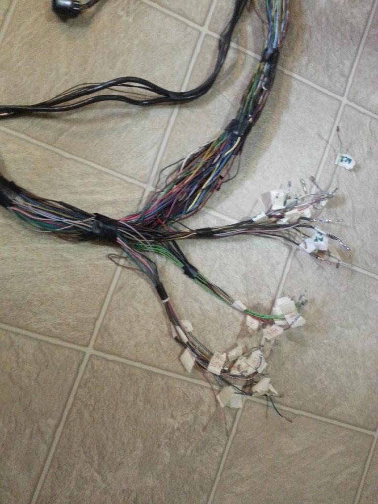


Most of my extra wires are near the auto transmission plugs . I have around 14 on that area... plain and simple ...sucker for extra wires


Extra wires and the 80 pin ECU connector. All these wires have already been extended.

This is the area where all the merging will happen

Last edited by gerrb; 02-03-14 at 05:22 AM.
#78
You remember this... front lower fusebox plugs and horn plug
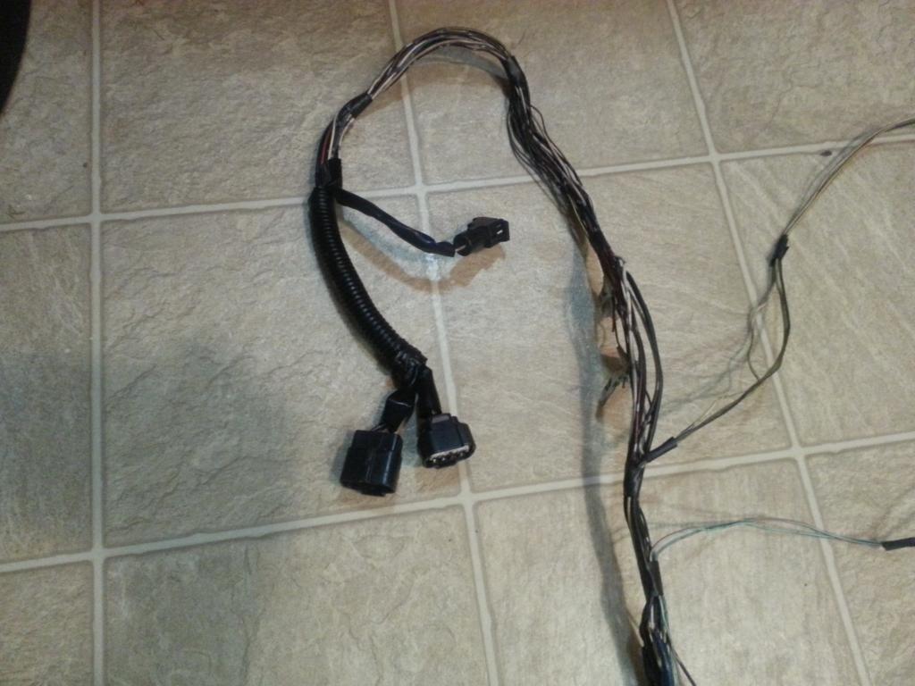
Alternator , power steering and starter plug
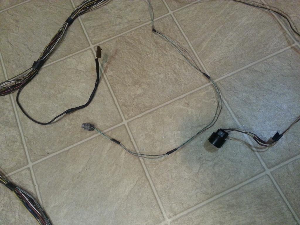
Heater Valve
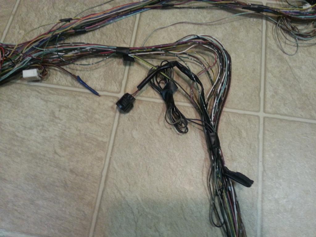
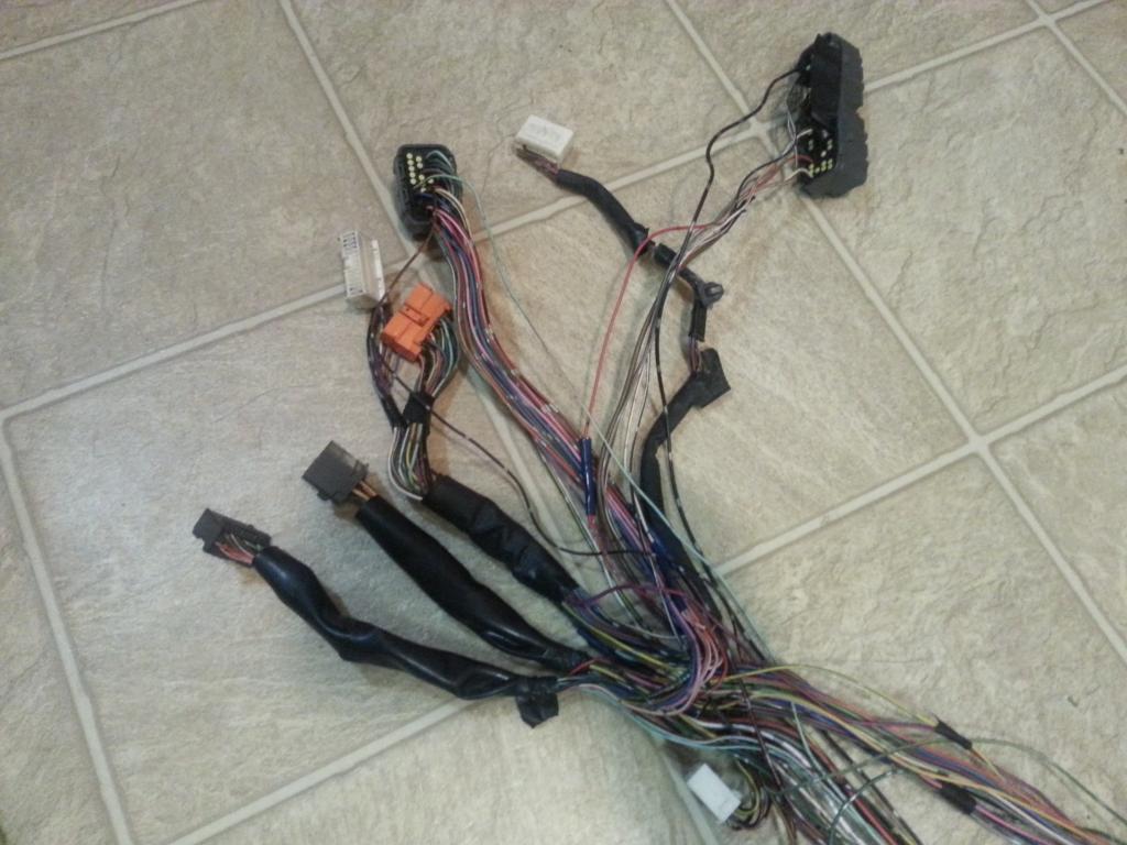
The 40 pin , IK1 , IK2 , IJ1 , IJK2 , II1 , Short Plugs
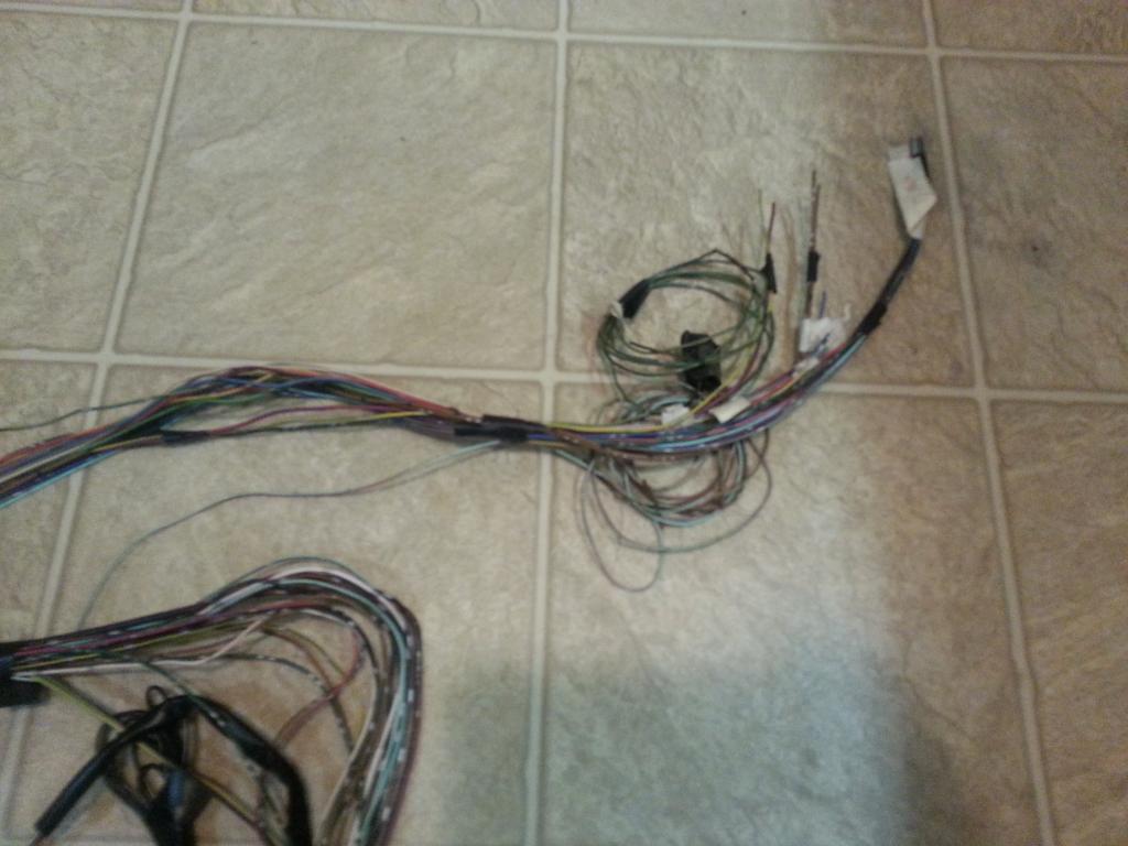
These are wires I just cut (from Diagnostic Port , Auto Transmission ) which I will use to connect to our Aristo 2jzgte harness. As I mentioned , for the manual transmission swap harness .. more wires have been removed and most of these you won't even have anymore. There is a plug with a wire rolled with this which I really don't know what it is for at least for now. But when I go through Part IV of the harness build I am sure I will find out since I will comb through the wiring diagrams looking for what else should be connected to the body plugs.

Alternator , power steering and starter plug

Heater Valve

The 40 pin , IK1 , IK2 , IJ1 , IJK2 , II1 , Short Plugs

These are wires I just cut (from Diagnostic Port , Auto Transmission ) which I will use to connect to our Aristo 2jzgte harness. As I mentioned , for the manual transmission swap harness .. more wires have been removed and most of these you won't even have anymore. There is a plug with a wire rolled with this which I really don't know what it is for at least for now. But when I go through Part IV of the harness build I am sure I will find out since I will comb through the wiring diagrams looking for what else should be connected to the body plugs.

Last edited by gerrb; 02-05-14 at 02:53 AM.
#79
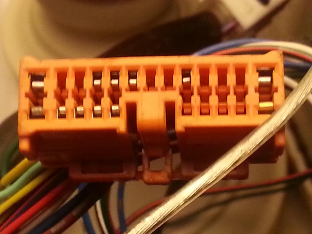
Just to prove what I said in the previous post that the Manual Transmission harness will have a lot fewer wires , this is how the two IK1 and 40 pin plugs look like
IK1 for the auto transmission has more pins / wires
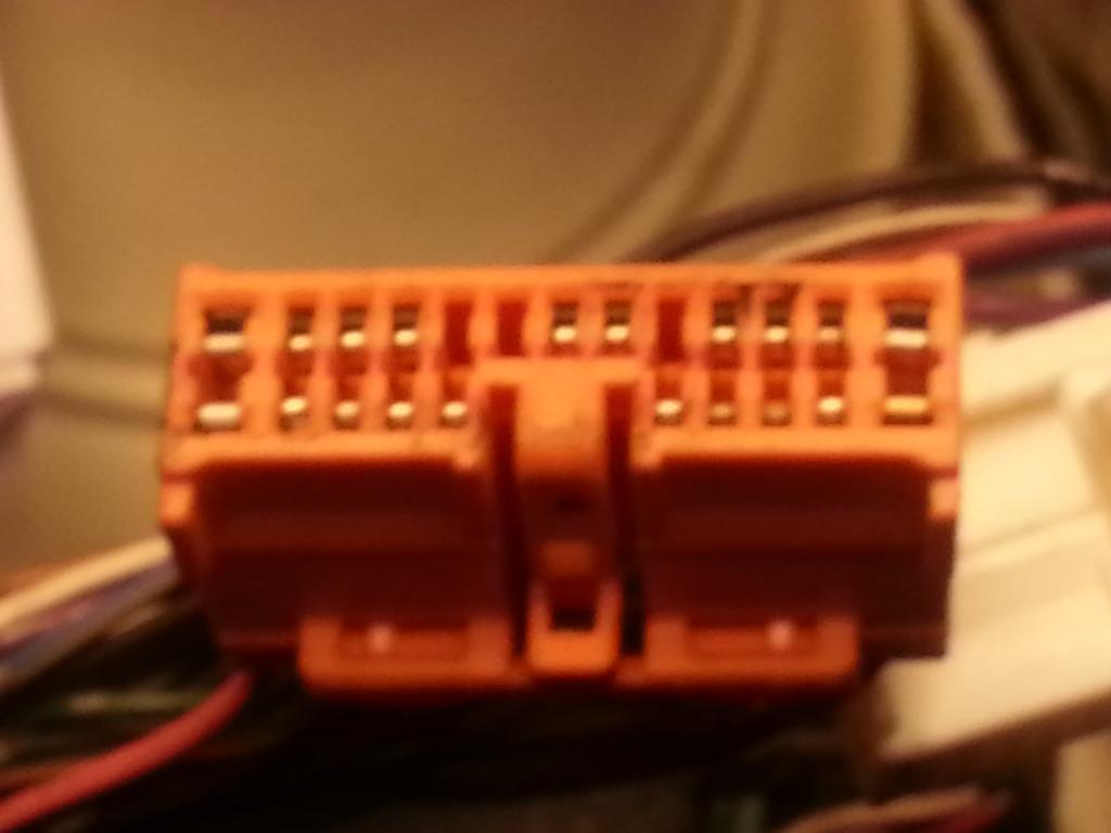
compared with the IK1 of the manual transmission
40 pin ECU connector for an SC300 with auto transmission has more pins / wires.
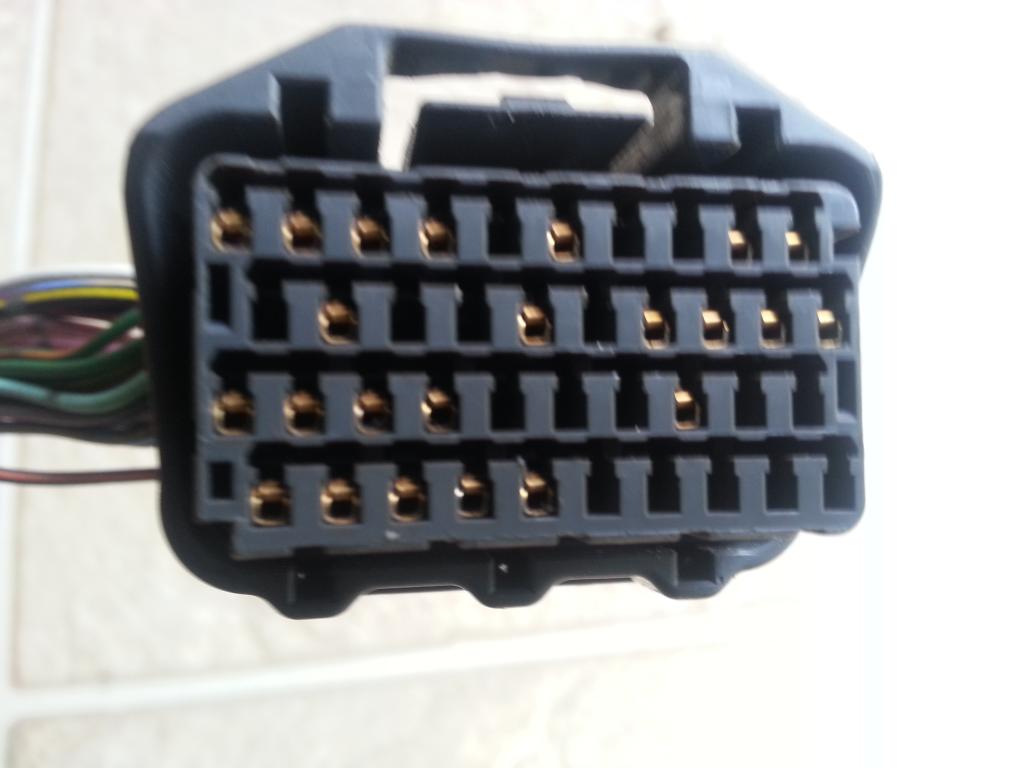
40 pin ECU connector for an SC300 with manual transmission
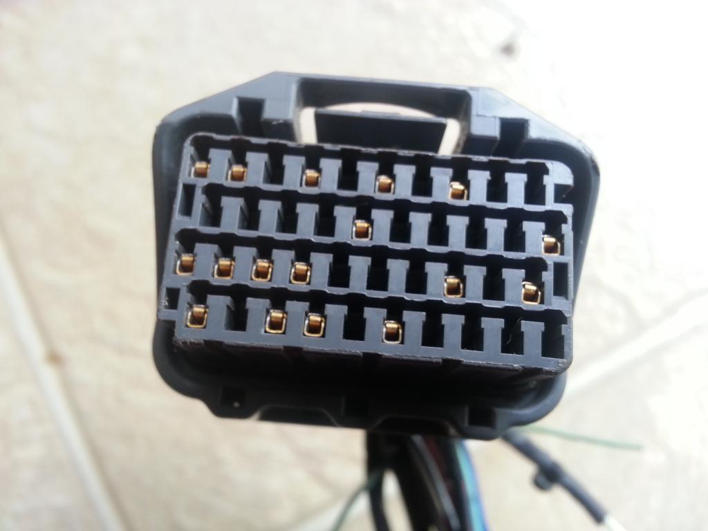
IK1 for the auto transmission has more pins / wires

compared with the IK1 of the manual transmission

40 pin ECU connector for an SC300 with auto transmission has more pins / wires.

40 pin ECU connector for an SC300 with manual transmission

Last edited by gerrb; 02-03-14 at 09:37 AM.
#80
From here , for those who already know what to do , they just overlay the SC300 harness on the 2jzgte harness or put them side by side and start connecting wires from the 2jzgte harness to the different pins on the 40 pin ECU connector and all the other plugs. They also start moving around or removing those wires / pins not needed on those plugs. That is easy for those who already know what to do.
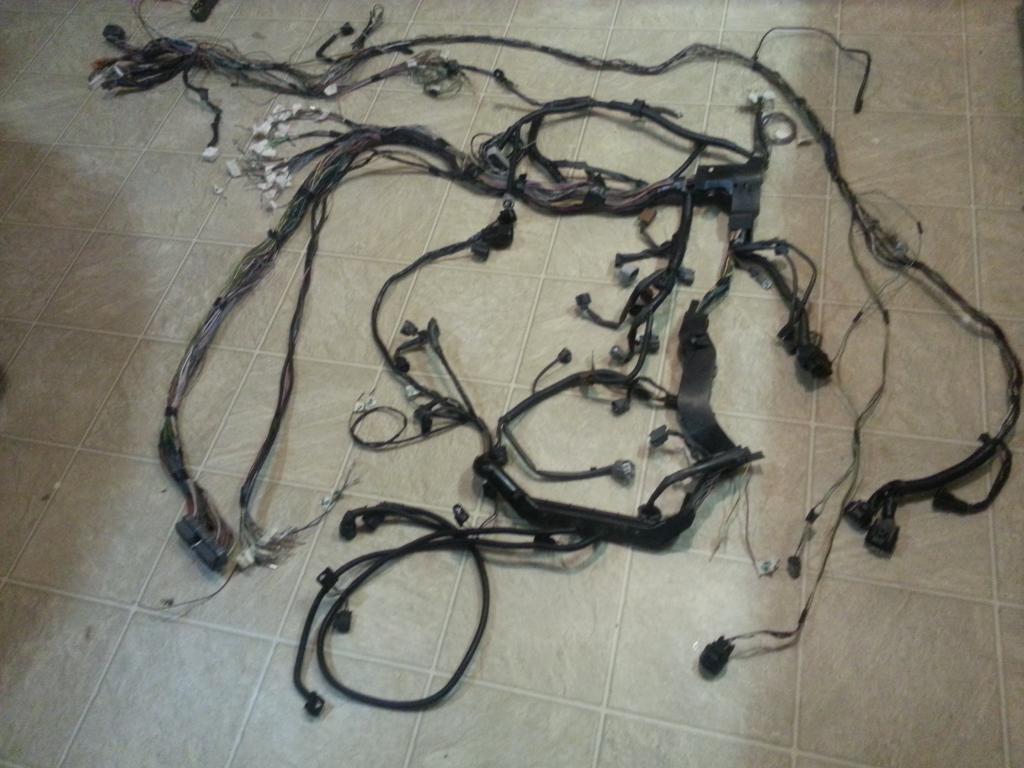
Just like pictured .... our Aristo 2jzgte harness with auto transmission plugs and the 1992 SC300 harness that will maintain the auto transmission plugs.
You already know where the fuse plugs , alternator , horn , power steering plugs should be in relation to your engine bay. So they need to be in their respective areas of the harness.
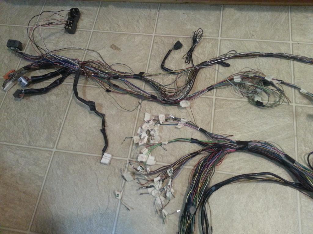
As I have said this is where all the merging of wires take place. Make sure that when you merge wires, those body plugs will be near the 80 pin ECU connector so watch out how long the wires of those body plugs you are merging should be.
The above process may still be confusing for those who never did it before . Take note what I said in the beginning of this harness build , some of those pins / wires that are currently on the different plugs like the SC300 40 pin ECU connector may not be used the same way as that on a 40 pin ECU connector for the 2jzgte. Remember ? Not because they are both 40 pin Connectors , all their pinning are exactly the same or used exactly the same way so you need to verify all the pins that are on those plugs.
So is it better to de-pin those plugs now and start connecting wires based on our CHART ? This depend on how well you know by now what is needed and not needed on a 2jzgte and from the 2jzge (SC300) connectors. So for those who have never done it before , probably so .... starting from a clean slate of plug will be less confusing for them and just add the pins one by one .
This you should have deduced from your CHART. Which wires from the Big Gray Aristo Plug goes to which pin of which plug. It is just another way of presenting what is already on your 2jzgte CHART . Let me explain this next chart a bit which I will call "Body Plug Chart" ..when I say AF1 , it means Aristo , Plug F , Pin 1. Let's take Pin 2 of IK1 . It simply means Pin 2 of the IK1 Connector (Orange with 23 pins) should be connected to the wire which we took out of the Aristo Plug E pin 7 (AE7) . If you have labeled those wires properly before , you should easily know which one it is. This same information , if you look at your CHART is already actually given but written differently under ARISTO CONNECTOR , PLUG E .... check it out , it's the SC3 data on parenthesis . So why am I presenting it this way ? Just for us to have a quick glance what is all going into the different pins of each body plug we are merging into the Aristo 2jzgte harness. We did the same thing on every plug of that 2jzgte harness .. remember your CHART ?
BODY PLUG CHART
IK1
1
2 <--> AE7
3 <--> AF10
4 <--> AF4
7 <--> Pin 1 of Noise Filter
8 <--> AF12 <--> Pin 1 of 4 Pin Igniter Connector
9 <--> AF9
11<--> AE13
12<--> AE4
13<--> AE8
14<--> AE11
16<--> AE9
17<--> AE10
20<--> AF8
IK2
9 <--> AE2
10<--> AD1
IJ1
1 <--> AC15
2
7 <--> AF6 <--> Pin 2 of 4 Pin Igniter Connector
10<--> AE14
12<--> AE3
II1
1 <--> AC1
4 <--> AC2
Short
4 <--> AE3 <--> Pin 2 of O2 sensor
EB1
1 <--> AC5
2
7 <--> AC1
EB2
1 <--> AE3 <--> AF1
40 PIN ECU CONNECTOR
6 <--> AE2
7 <--> AE13
9 <--> AE9
10<--> AE10
19<--> AE7
20<--> AF4
31<--> AE3
Let me remind you though , not because you have connected all those wires from our Aristo 2jzgte harness to those body plugs , it is a done deal .. NO it is not , there are other pins on those body plugs that needs to have wires / pins . Those we will cover on PART IV OTHERS. I will post the diagrams also just for you to know where are they coming from (e.g. A pin from one body plug maybe connected to another pin of another body plug or let's say you currently have a car with auto transmission and you are converting to a manual transmission, there are wires / pins you need to work on. That car won't start without modifying / repinning some plugs (hint : a car with an auto transmission has a PARK safety switch which you need to bypass ).
Please take note :
1) From now on when I say Body Plugs , I am referring to all the plugs we extracted from the SC300 harness meaning the 40 pin ECU connector and other plugs like fuse box plugs are included.
2) Informations that are presented on the MERGING PROCESS is all for the SC300 car since I am dealing with body plugs for the SC300. If you have the SC400 or MKIV NA , use the pertinent informations on parenthesis from our 2jzgte CHART.
3) Before you start doing the merging process, You make sure you have enough wires and pins for the different body plugs. Why pins ? It is because a 2jzgte setup will use more pins. Like the 40 pin ECU Connector for a 2jzgte will have more pins / wires than the 40 pin ECU Connector you currently have on your SC300. Or if you have an SC300 with manual transmission and want to swap a 2jzgte with auto transmission , then you know you definitely need more pins / wires which your current manual transmission body plugs do not have.
So where do you get those wires and pins for those body plugs ? Somewhere , I remember saying (in one of the Q&A on the other thread) , if you can get hold of another old harness (from a 1uzfe, 1jzgte , 2jzge or any toyota car with the same plugs) you can use for extensions then you will also have extra pins for the same body plugs.
Just like pictured .... our Aristo 2jzgte harness with auto transmission plugs and the 1992 SC300 harness that will maintain the auto transmission plugs.

You already know where the fuse plugs , alternator , horn , power steering plugs should be in relation to your engine bay. So they need to be in their respective areas of the harness.

As I have said this is where all the merging of wires take place. Make sure that when you merge wires, those body plugs will be near the 80 pin ECU connector so watch out how long the wires of those body plugs you are merging should be.

The above process may still be confusing for those who never did it before . Take note what I said in the beginning of this harness build , some of those pins / wires that are currently on the different plugs like the SC300 40 pin ECU connector may not be used the same way as that on a 40 pin ECU connector for the 2jzgte. Remember ? Not because they are both 40 pin Connectors , all their pinning are exactly the same or used exactly the same way so you need to verify all the pins that are on those plugs.
So is it better to de-pin those plugs now and start connecting wires based on our CHART ? This depend on how well you know by now what is needed and not needed on a 2jzgte and from the 2jzge (SC300) connectors. So for those who have never done it before , probably so .... starting from a clean slate of plug will be less confusing for them and just add the pins one by one .
This you should have deduced from your CHART. Which wires from the Big Gray Aristo Plug goes to which pin of which plug. It is just another way of presenting what is already on your 2jzgte CHART . Let me explain this next chart a bit which I will call "Body Plug Chart" ..when I say AF1 , it means Aristo , Plug F , Pin 1. Let's take Pin 2 of IK1 . It simply means Pin 2 of the IK1 Connector (Orange with 23 pins) should be connected to the wire which we took out of the Aristo Plug E pin 7 (AE7) . If you have labeled those wires properly before , you should easily know which one it is. This same information , if you look at your CHART is already actually given but written differently under ARISTO CONNECTOR , PLUG E .... check it out , it's the SC3 data on parenthesis . So why am I presenting it this way ? Just for us to have a quick glance what is all going into the different pins of each body plug we are merging into the Aristo 2jzgte harness. We did the same thing on every plug of that 2jzgte harness .. remember your CHART ?
BODY PLUG CHART
IK1
1
2 <--> AE7
3 <--> AF10
4 <--> AF4
7 <--> Pin 1 of Noise Filter
8 <--> AF12 <--> Pin 1 of 4 Pin Igniter Connector
9 <--> AF9
11<--> AE13
12<--> AE4
13<--> AE8
14<--> AE11
16<--> AE9
17<--> AE10
20<--> AF8
IK2
9 <--> AE2
10<--> AD1
IJ1
1 <--> AC15
2
7 <--> AF6 <--> Pin 2 of 4 Pin Igniter Connector
10<--> AE14
12<--> AE3
II1
1 <--> AC1
4 <--> AC2
Short
4 <--> AE3 <--> Pin 2 of O2 sensor
EB1
1 <--> AC5
2
7 <--> AC1
EB2
1 <--> AE3 <--> AF1
40 PIN ECU CONNECTOR
6 <--> AE2
7 <--> AE13
9 <--> AE9
10<--> AE10
19<--> AE7
20<--> AF4
31<--> AE3
Let me remind you though , not because you have connected all those wires from our Aristo 2jzgte harness to those body plugs , it is a done deal .. NO it is not , there are other pins on those body plugs that needs to have wires / pins . Those we will cover on PART IV OTHERS. I will post the diagrams also just for you to know where are they coming from (e.g. A pin from one body plug maybe connected to another pin of another body plug or let's say you currently have a car with auto transmission and you are converting to a manual transmission, there are wires / pins you need to work on. That car won't start without modifying / repinning some plugs (hint : a car with an auto transmission has a PARK safety switch which you need to bypass ).
Please take note :
1) From now on when I say Body Plugs , I am referring to all the plugs we extracted from the SC300 harness meaning the 40 pin ECU connector and other plugs like fuse box plugs are included.
2) Informations that are presented on the MERGING PROCESS is all for the SC300 car since I am dealing with body plugs for the SC300. If you have the SC400 or MKIV NA , use the pertinent informations on parenthesis from our 2jzgte CHART.
3) Before you start doing the merging process, You make sure you have enough wires and pins for the different body plugs. Why pins ? It is because a 2jzgte setup will use more pins. Like the 40 pin ECU Connector for a 2jzgte will have more pins / wires than the 40 pin ECU Connector you currently have on your SC300. Or if you have an SC300 with manual transmission and want to swap a 2jzgte with auto transmission , then you know you definitely need more pins / wires which your current manual transmission body plugs do not have.
So where do you get those wires and pins for those body plugs ? Somewhere , I remember saying (in one of the Q&A on the other thread) , if you can get hold of another old harness (from a 1uzfe, 1jzgte , 2jzge or any toyota car with the same plugs) you can use for extensions then you will also have extra pins for the same body plugs.
Last edited by gerrb; 02-04-14 at 01:26 AM.
#81
I will post pictures here (post 81) of the SC300 harness body plugs wires soldered / merged with the Aristo 2jzgte harness once am back in town. I haven't actually done that yet on the two harnesss as of today  . But would like to continue posting on this thread on my free time (got lots of it sitting on the plane & waiting at the airports ) info in which I don't need the actual harness
  .
.
 . But would like to continue posting on this thread on my free time (got lots of it sitting on the plane & waiting at the airports ) info in which I don't need the actual harness
  .
.
Last edited by gerrb; 02-03-14 at 11:04 AM.
#83
Part IV : OTHERS
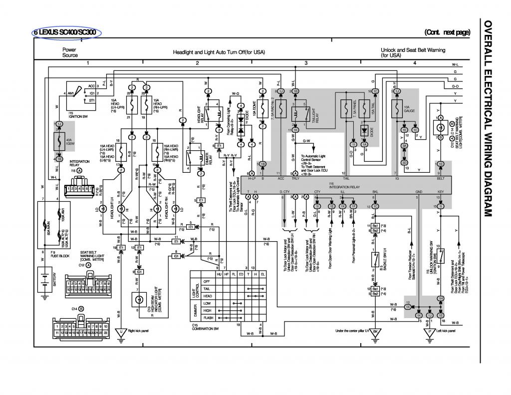
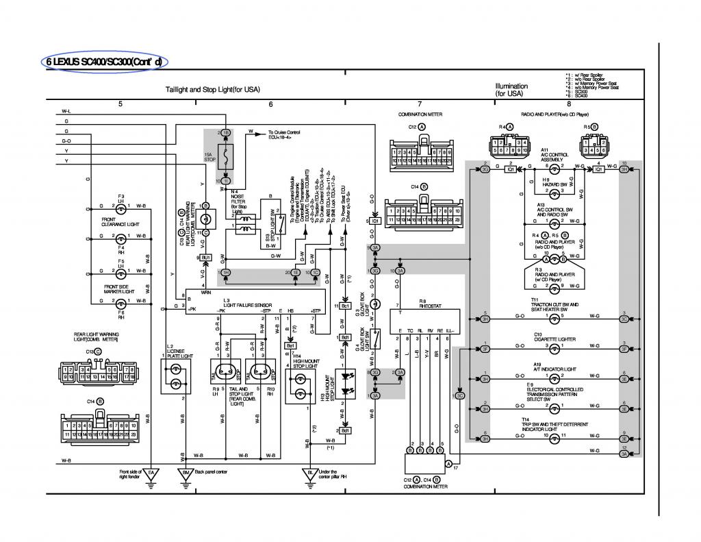
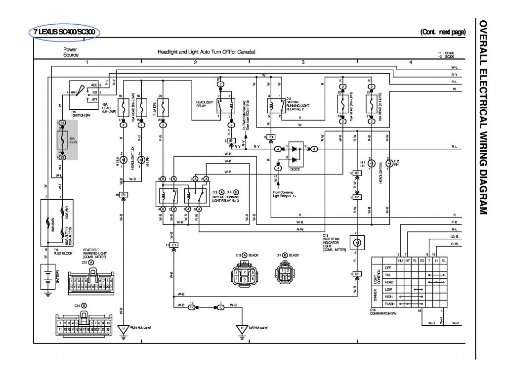
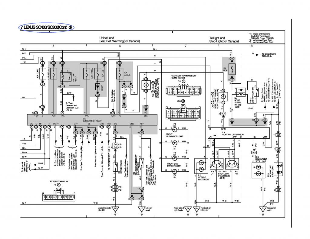
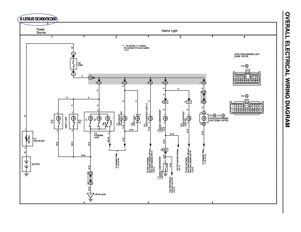
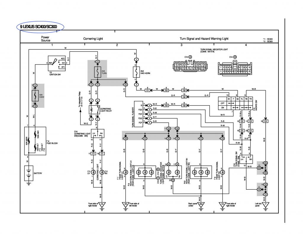
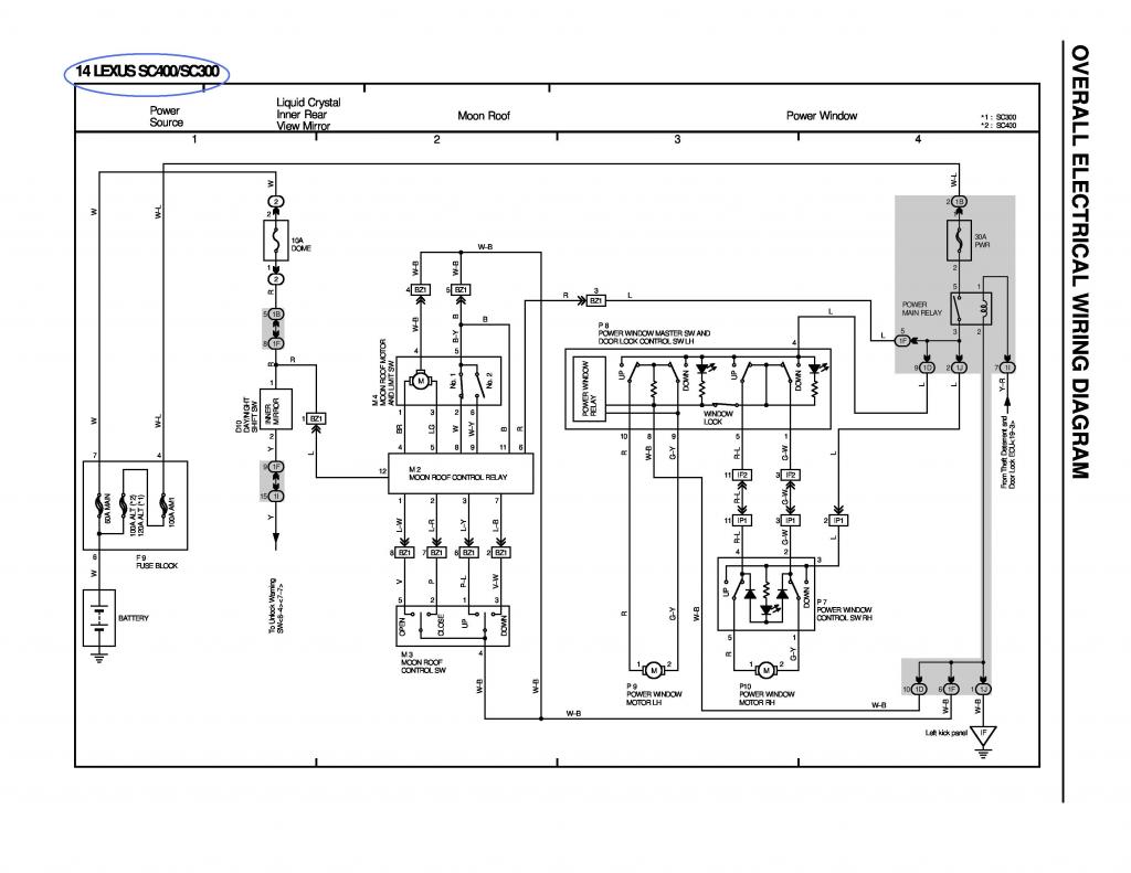
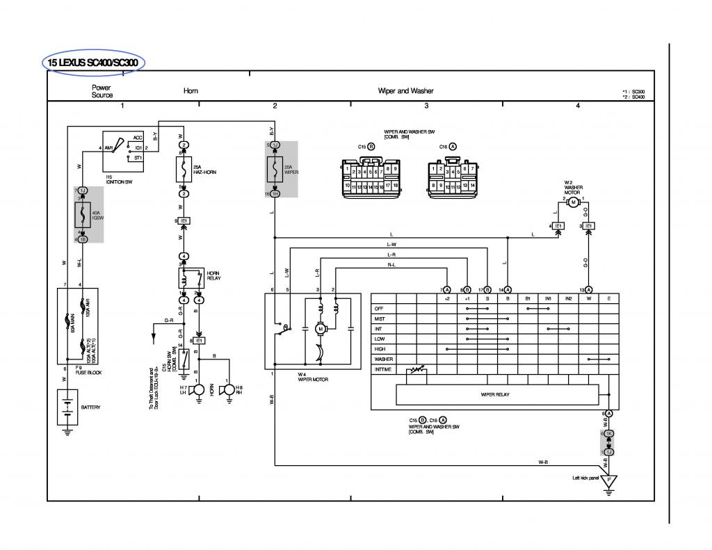
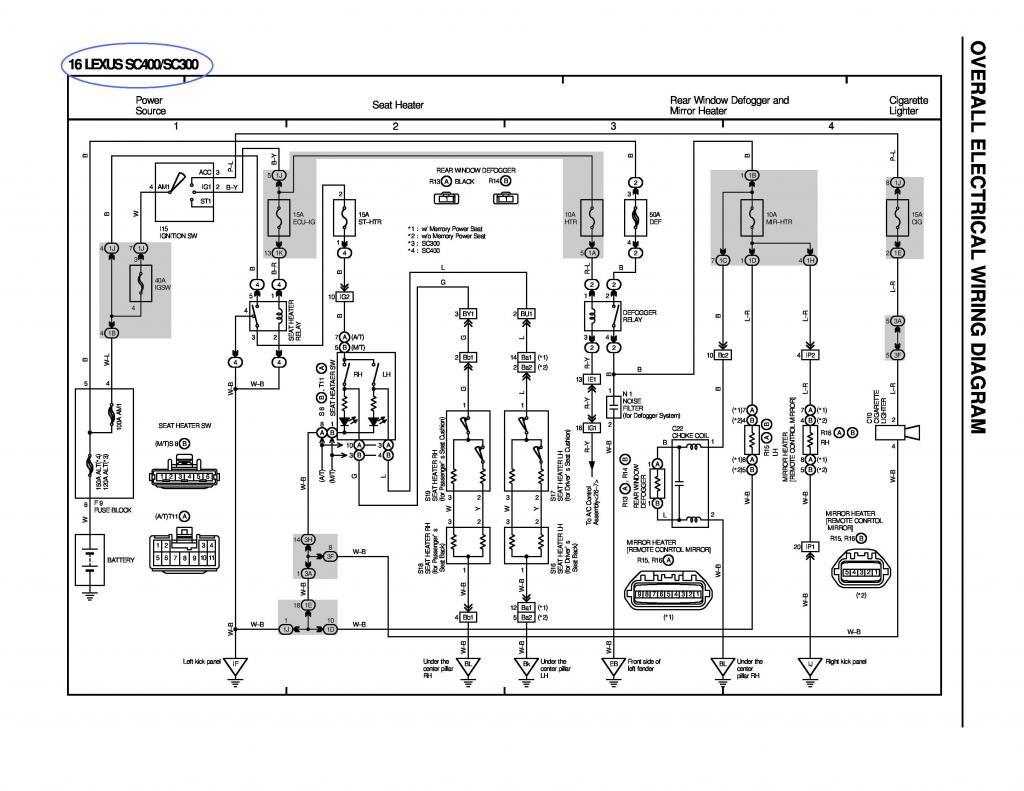
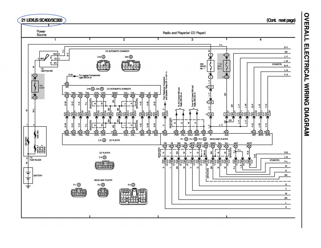
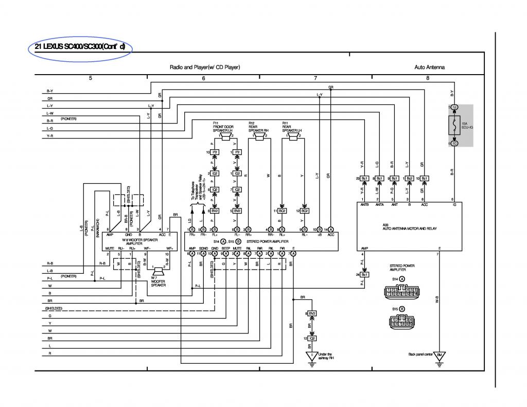
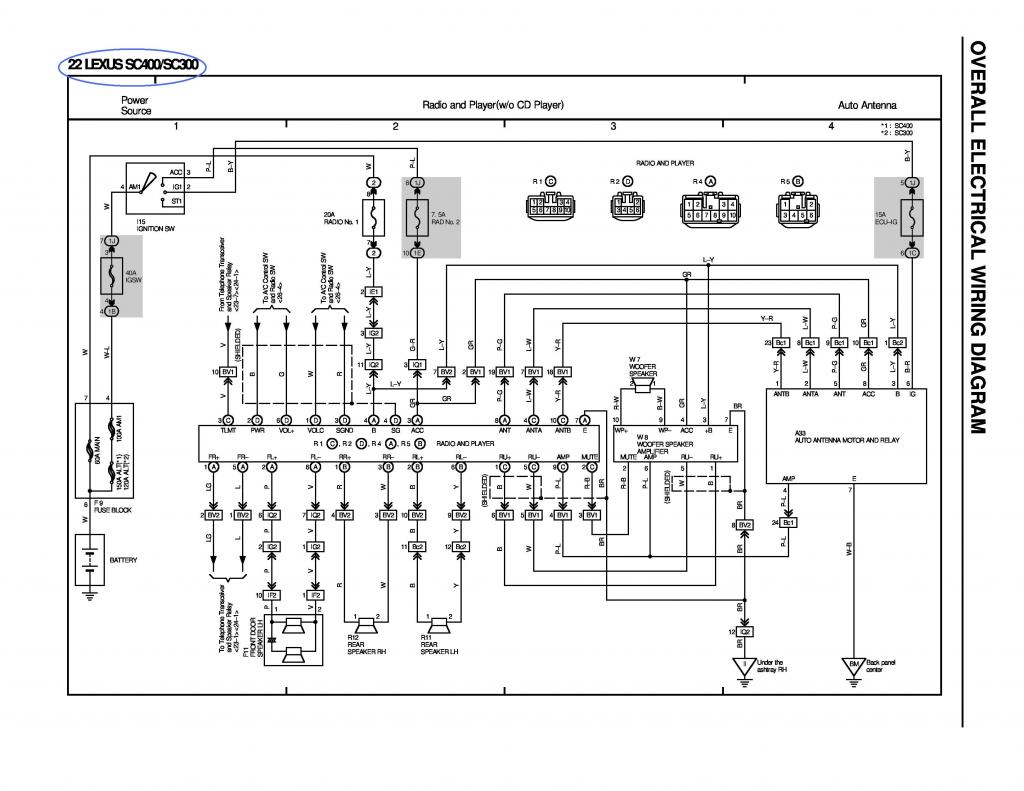
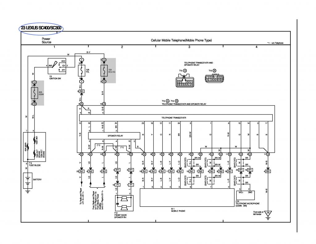
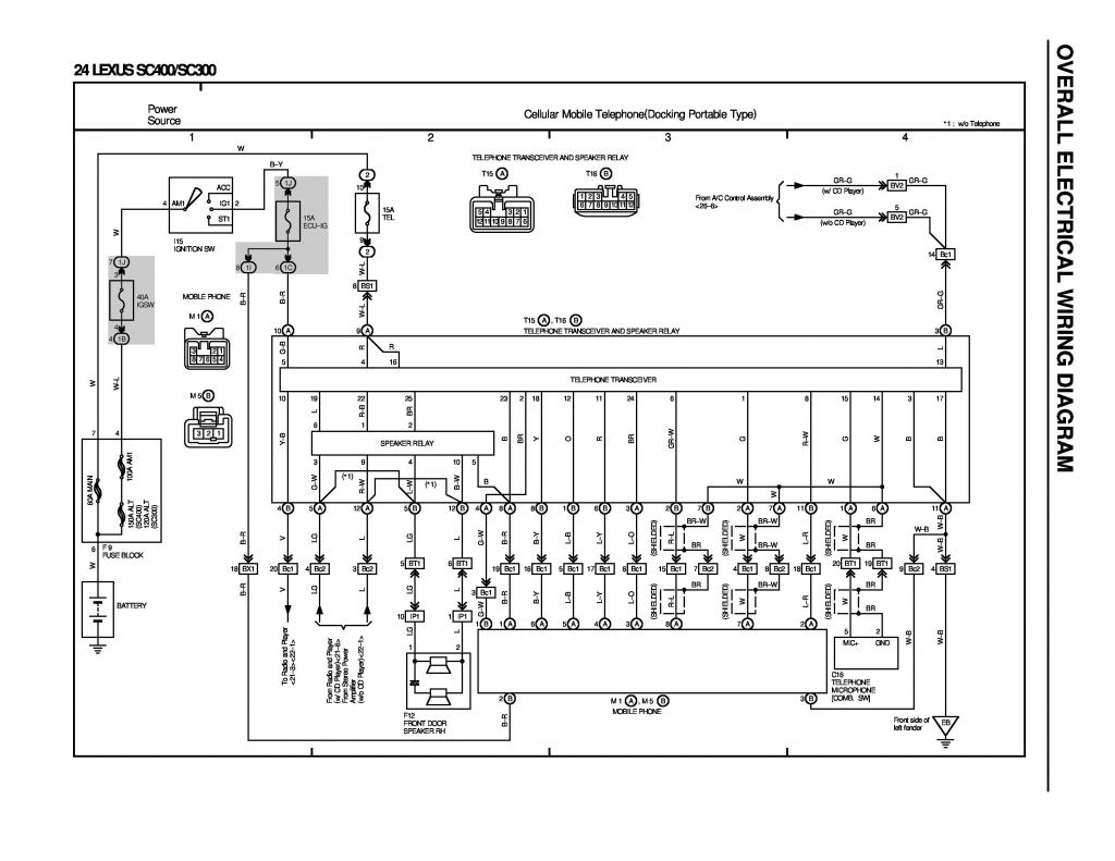
On this part of the 2jzgte harness build , we will go through all the SC300 / SC400 / MKIV wiring diagrams. We will try to find those pins and wirings that go to the different body plugs / connectors. Though there are not a lot of differences between the year / model of cars , still there are differences on their wirings. If you can go through your year / model wiring diagrams , that will be the best.
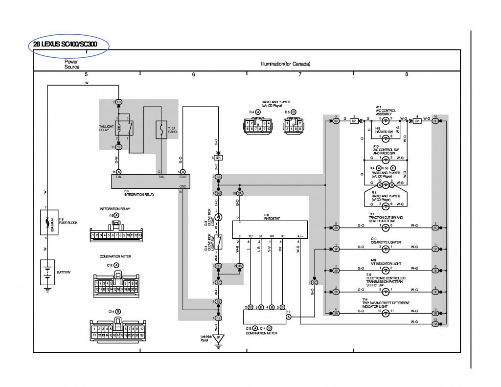
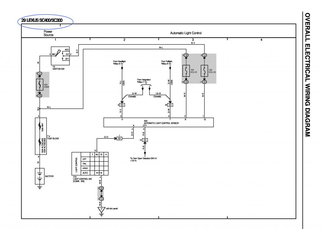
I know some of you may not have the complete wiring diagrams for the SC300 or SC400 or MKIV NA. I will post them here maybe 5 to 8 pages per post so you have all the wiring info you need for your car while we look for those wires that go through the Body Plugs and ECU Connectors. Just like I said at the start , we will try to put all the info you need in one thread so you will find it easier to build a 2jzgte wiring harness and have the tools to verify what you are doing. If you couldn't read the diagrams because of the picture size , click on the picture , and magnify them there by clicking the + sign to enlarge the picture .
.
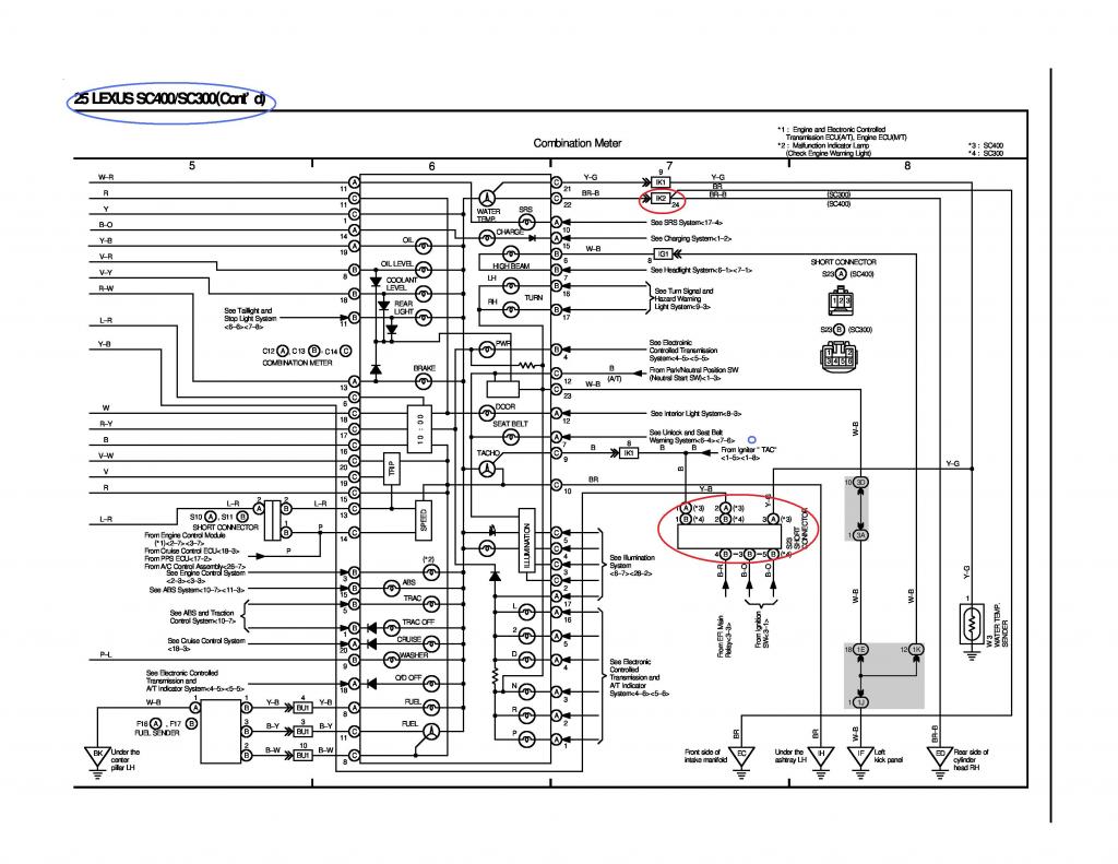
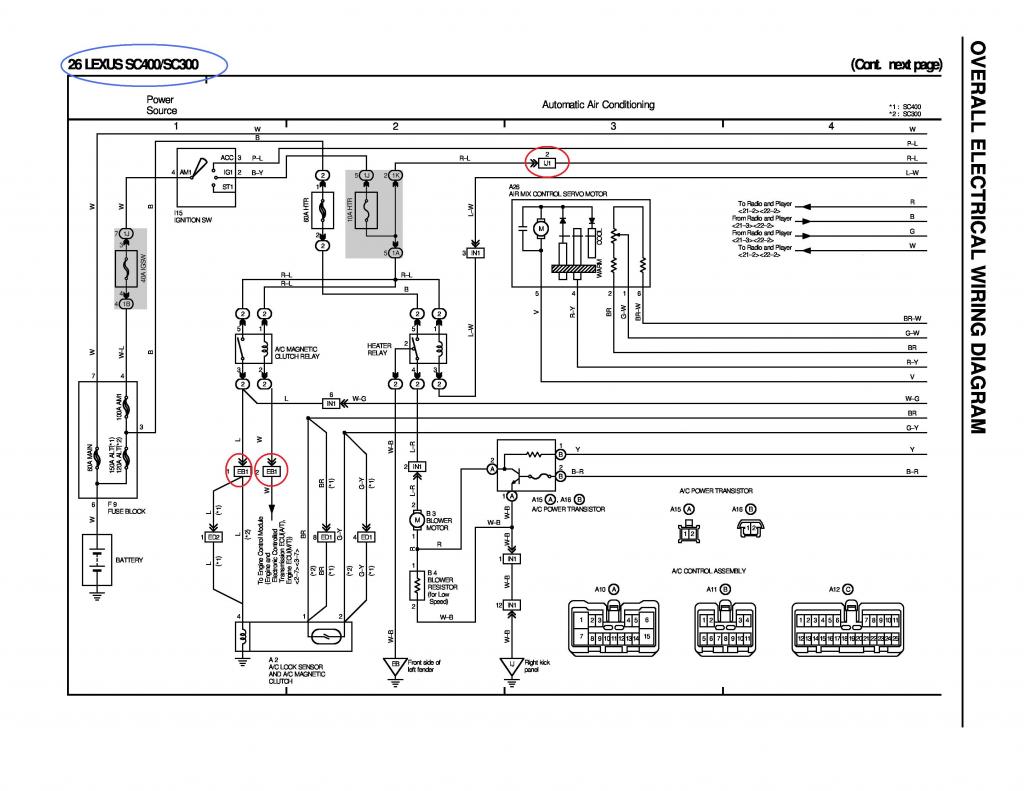
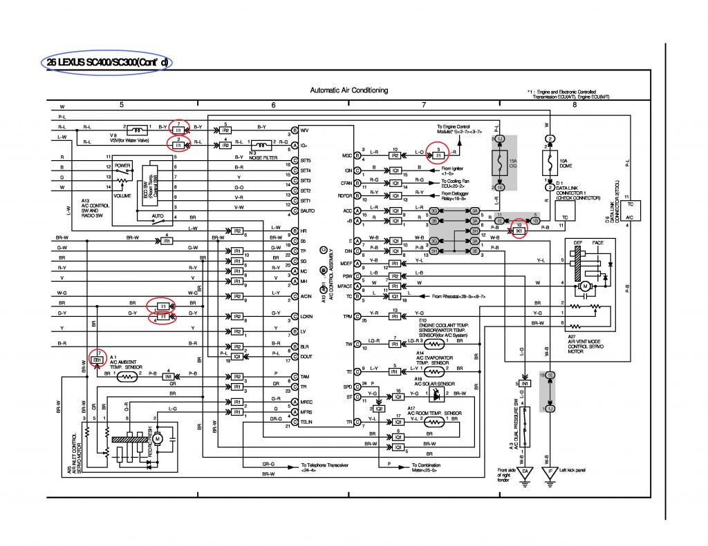
If on a diagram , you see red ellipsis, that means we haven't covered that and you will have to add that pin / wire on your body plug. There maybe some pins / wire that has no ellipsis but I still added on the list just because during the time I was working on the JPEGs I forgot to encircle them but noticed them during the write-up... sorry about that. Going through the diagrams, you should be able to complete the list of wires that go to the body plugs.
Remember , as I kept on mentioning ,I am trying to show you the process of how to do it. This write-up is not for you just to copy whatever I have written. I am pretty sure there will still be typo errors or might have missed something even if I have been proof reading what I wrote. Knowing the process, you will be able to verify for yourself what have been written here . Diagrams I am posting here are from 1992-1994 SC300/SC400 . There are some differences with the later years so make sure you use the diagrams for your particular car year model.
[SIZE="5"]SC300 / SC400 Wiring Diagrams[/SIZE]
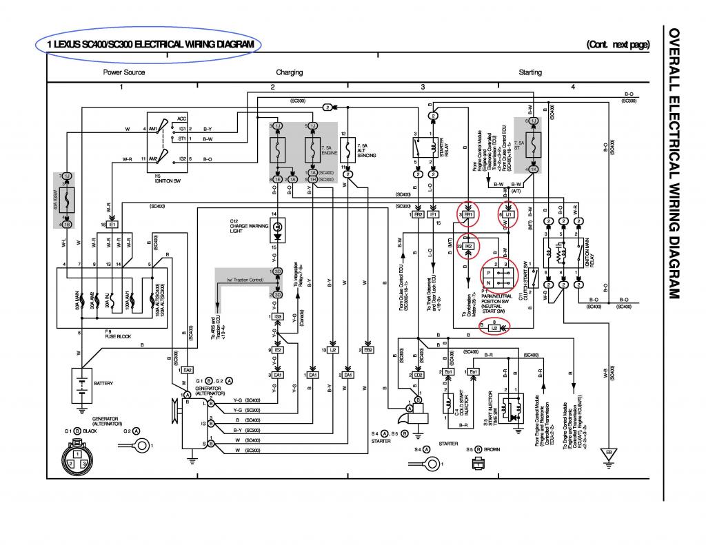
Going through each diagram , we will look for each body plug with their associated pins and wires.
[SIZE="3"]For SC300[/SIZE]
Alternator Connector
Pin 1 of Alternator Connector goes to Pin 2 of the EB2 Connector
Pin 2 of Alternator Connector goes to Pin 5 of the IJ1 Connector
Pin 3 of Alternator Connector goes to Pin 13 of the IJ2 Connector
EB2
Pin 2 of EB2 goes to Pin 1 of the Alternator Connector
IJ1
Pin 5 of IJ1 goes to Pin 2 of the Alternator Connector
IJ2
Pin 13 of IJ2 goes to Pin 3 of the Alternator Connector
[SIZE="3"]For SC300 & SC400[/SIZE]
Starter Connector
Pin 1 of the Starter Connector goes to Pin 1 of the EB2 Connector
EB2
Pin 1 of EB2 goes to Pin 1 of the Starter Connector
EB1
Pin 3 of EB1 goes to Pin 23 of IK2 & to Pin 5 of the Park / Neutral Switch (& to Pin 8 of IJ2 (Manual Transmission Cars from Factory))
IK2
Pin 23 of IK2 goes to Pin 3 of EB1 & to Pin 5 of the Park / Neutral Switch
IJ1
Pin 6 of IJ1 goes to Pin 6 of Park / Neutral Switch
IJ2
Pin 8 of IJ2 goes to Pin 3 of EB1 (for manual transmission cars only)
NOTE :
a) For those who originally have an auto transmission car and are converting to a manual transmission, , you will need to jump the pin 2 & 3 of the Park / Neutral switch which is like connecting Pin 23 of IK2 to Pin 6 of IJ1 . If you don't do that , your car is not going to start because of that Park / Neutral Safety switch that is not activated due to the fact that you don't anymore have an auto transmission.
b) On the diagram above, you see connections point EA1-1, EA1-2, EA1-3, EA2-1 for the SC400 alternator. Those are mere hard wires. There is no actual plug. So for the SC400 , you need to connect your alternator plug to those wires. The plug and wiring for their alternator is not incorporated on the engine harness while that of the SC300 is.
c) From the starter you also see the wire goes to connector ED2-2 before it goes to EB2-1 for the SC400. Since you are going 2jzgte , you won't have that ED2-2 connector anymore so the starter wire goes directly to Pin 1 of fuse box plug EB2 just like that of the SC300.
d) There are other connectors for the SC400 like Ee1-1 , Ee1-2 . Since you are doing away with the 1uzfe and installing a 2jzgte , you won't have those anymore.
e) The beauty of going through these diagrams at this point is if you miss something along the process, there is a possibility that you will catch it. I was scanning on the body plug pins associated with the diagnostic port, then I realized there is a pressure switch for an SC300 which the SC400 did not have on the diagram . The wire goes to Pin 35 of the 40 pin ECU connector. During the process of elimination I actually noticed the wire of that plug going to Pin 35 of the 40 pin ECU and I just put it aside for now till I figure out what it is. The diagram helped me figure out what it was for.
f) When you see an arrow on a diagram and numbers in parenthesis , the numbers in parenthesis tells you the page and section where that diagram goes or comes from .
g) Updating your Body Plugs Chart helps you see what is already filled up on your body plugs
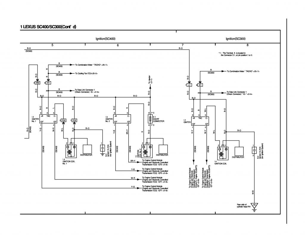
For SC300
IJ1
Pin 7 provides power to B+ of Igniter, Coil and Pin 1 of Filter
IK1
Pin 8 goes to Igniter TAC signal and to Pin 19 of Check Connector Data Link
For SC400
EB2
Pin 2 provides power to B+ of Igniter, Coil and Pin 1 of Filter
IK1
Pin 8 goes to Igniter TAC signal and to Pin 19 of Check Connector Data Link
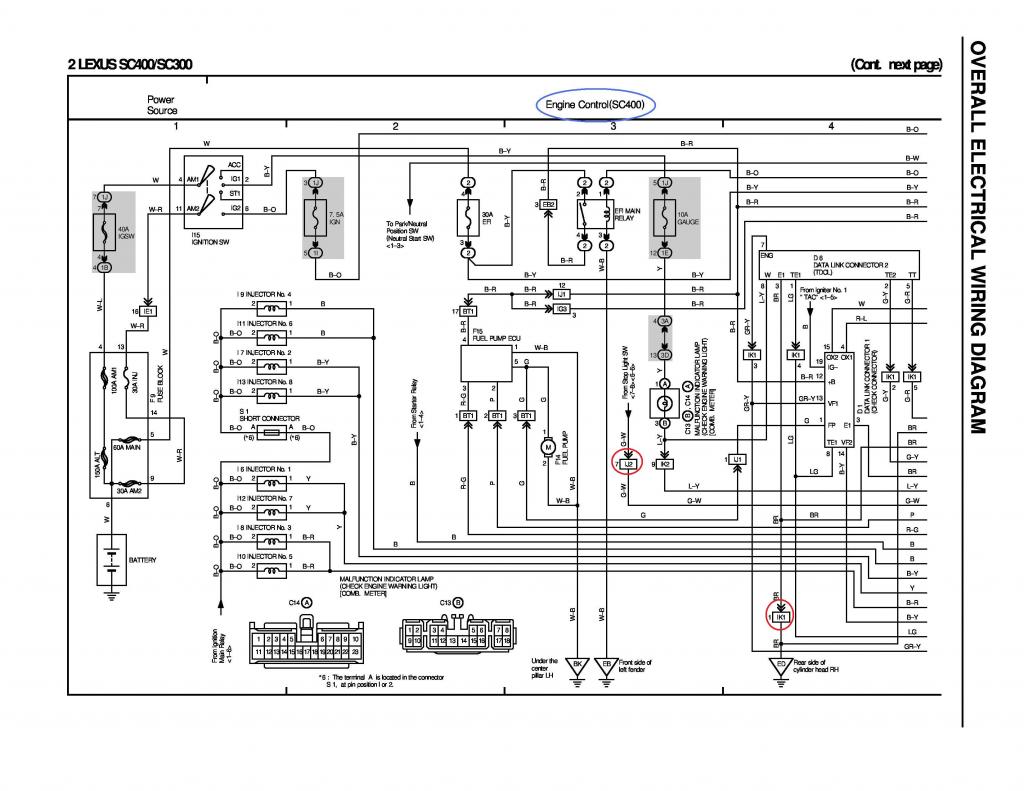
For SC400
IK1
Pin 1 of IK1 goes to Rear Side of Cylinder Head Ground and to ground of Oxygen sensors
Pin 2 of IK1 goes to Pin 19 of the 40 pin ECU Connector
Pin 3 of IK1 goes to Pin 29 of the 80 pin ECU Connector and Pin 13 of Check Connector Data Link
Pin 4 of IK1 goes to Pin 20 of the 40 pin ECU Connector and Pin 8 of Check Connector Data Link
Pin 5 of IK1 goes to Pin 17 of the 40 pin ECU Connector (diagram above shows pin 17 of the 80 pin but that is a mistake.. it should be Pin 17 of the 40 pin connector which is for TT Test Terminal)
IK2
Pin 9 of IK2 goes to Pin 6 of the 40 pin ECU Connector
IJ1
Pin 1 goes to Pin1 of the Check Connector Data Link
Pin 12 goes to pin 3 of EB2 and to Pin 2 of O2 sensors, Pin 31,32 of 40 Pin ECU Connector, Pin 2,5 of IACV and a pin of the VSVs
IJ2
Pin 7 of IJ2 goes to Pin 4 of the 40 pin ECU Connector
EB2
Pin 3 goes to pin 12 of IJ1 and to Pin 2 of O2 sensors, Pin 31,32 of 40 Pin ECU Connector, Pin 2,5 of IACV and a pin of the VSVs
Note : You are not obliged to complete the pins on the Diagnostic Port. They are optional. You would simply loose certain diagnostic capabilities. I say this because it may be hard to find the necessary pins to add. If you can better.
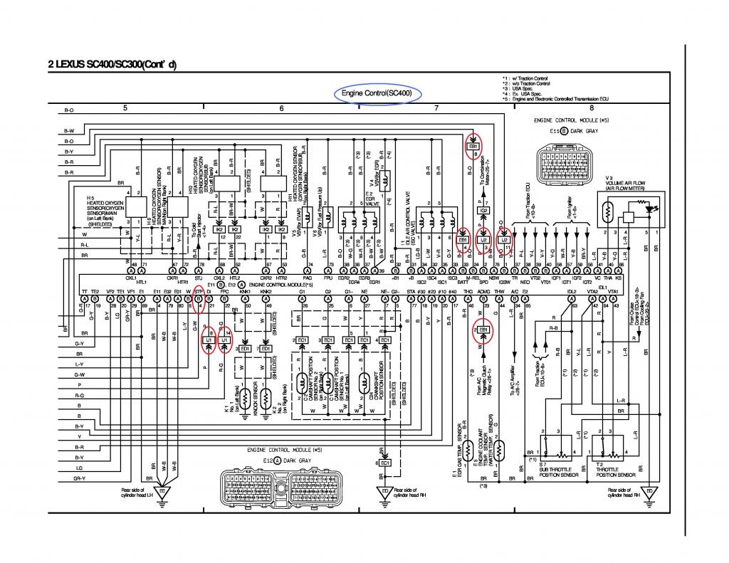
For SC400
IJ1
Pin 8 of IJ1 goes to Pin 21 of the 40 pin ECU Connector
Pin 14 of IJ1 goes to Pin 22 of the 40 pin ECU Connector
IJ2
Pin 3 of IJ2 goes to Pine 2 of the 40 pin ECU Connector
Pin 11 of IJ2 goes to Pin 1 of the 40 pin ECU Connector
EB1
Pin 2 of EB1 goes to Pin 23 of the 40 pin ECU Connector
Pin 4 of EB1 goes to Pin 33 of the 40 pin ECU Connector
Pin 8 of EB1 goes to Pin 24 of the 40 pin ECU Connector
IK2 You can remove these pins / wire since you don't need those oxygen sensors on those pins
Pin 1 of IK2 goes to Pin 67 of 80 pin ECU Connector
Pin 8 of IK2 goes to Pin 53 of 80 pin ECU Connector
Pin 12 of IK2 goes to Pin 68 of 80 pin ECU Connector
Pin 22 of IK2 goes to Pin 52 of 80 pin ECU Connector

FOR SC300
IK1
Pin 1 of IK1 goes to Pin 3 of the Diagnostic Port (You can add this since you are now going 2jzgte)
Pin 2 of IK1 goes to Pin 19 of the 40 pin ECU Connector
Pin 3 of IK1 goes to Pin 13 of the D1 Check Connector Data Link and Pin 29 of the 80 pin ECU Connector
Pin 4 of IK1 goes to Pin 8 of the D1 Check Connector Data Link and Pin 20 of the 40 pin ECU Connector
Pin 5 of IK1 goes to Pin 17 of the 40 pin ECU Connector
IK2
Pin 9 of IK2 goes to Pin 6 of the 40 pin ECU Connector
IJ1
Pin 1 of IJ1 goes to Pin 1 of the D1 Check Connector Data Link
Pin 7 of IJ1 goes to Pin 5 of Short Connector and Pin 2 of Injectors 1,2,3,4,5,6
Pin 12 of IJ1 goes to Pin 12 of the D1 Check Connector Data Link and Pin 1 of EB2 and Pin 31/32 of the 40 pin ECU Connector and Pin 2,5 of IACV and a Pin of the VSVs & Pin 4 of Short Connedtor
IJ2
Pin 7 of IJ2 goes to Pin 4 of the 40 pin ECU Connector
EB2
Pin 1 of EB2 goes to Pin 12 of the D1 Check Connector Data Link and Pin 12 of IJ1 and Pin 31/32 of the 40 pin ECU Connector and Pin 2,5 of IACV and a Pin of the VSVs & Pin 4 of Short Connedtor
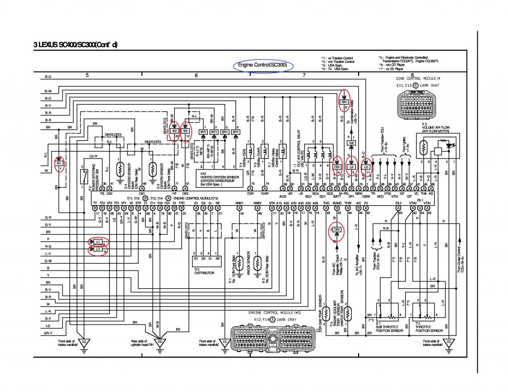
For SC300
IJ1
Pin 8 of IJ1 goes to Pin 21 of the 40 pin ECU Connector
Pin 14 of IJ1 goes to Pin 22 of the 40 pin ECU Connector
IJ2
Pin 3 of IJ2 goes to Pine 2 of the 40 pin ECU Connector
Pin 11 of IJ2 goes to Pin 1 of the 40 pin ECU Connector
EB1
Pin 2 of EB1 goes to Pin 23 of the 40 pin ECU Connector
Pin 4 of EB1 goes to Pin 33 of the 40 pin ECU Connector
Pin 8 of EB1 goes to Pin 24 of the 40 pin ECU Connector
IK1
Pin 1 goes to Pin 1 of the Power Steering Pressure Switch
IK2 You can take these out if you are not using an O2 Sensor on your swap
Pin 12 of IK2 goes to Pin 61 of the 80 pin ECU Connector
Pin 22 of IK2 goes to Pin 71 of the 80 pin ECU Connector
Power Steering Pressure Switch
Pin 1 goes to Pin 1 of IK1
Pin 2 goes to Pin 35 of the 40 pin ECU Connector
On this part of the 2jzgte harness build , we will go through all the SC300 / SC400 / MKIV wiring diagrams. We will try to find those pins and wirings that go to the different body plugs / connectors. Though there are not a lot of differences between the year / model of cars , still there are differences on their wirings. If you can go through your year / model wiring diagrams , that will be the best.
I know some of you may not have the complete wiring diagrams for the SC300 or SC400 or MKIV NA. I will post them here maybe 5 to 8 pages per post so you have all the wiring info you need for your car while we look for those wires that go through the Body Plugs and ECU Connectors. Just like I said at the start , we will try to put all the info you need in one thread so you will find it easier to build a 2jzgte wiring harness and have the tools to verify what you are doing. If you couldn't read the diagrams because of the picture size , click on the picture , and magnify them there by clicking the + sign to enlarge the picture
 .
.If on a diagram , you see red ellipsis, that means we haven't covered that and you will have to add that pin / wire on your body plug. There maybe some pins / wire that has no ellipsis but I still added on the list just because during the time I was working on the JPEGs I forgot to encircle them but noticed them during the write-up... sorry about that. Going through the diagrams, you should be able to complete the list of wires that go to the body plugs.
Remember , as I kept on mentioning ,I am trying to show you the process of how to do it. This write-up is not for you just to copy whatever I have written. I am pretty sure there will still be typo errors or might have missed something even if I have been proof reading what I wrote. Knowing the process, you will be able to verify for yourself what have been written here . Diagrams I am posting here are from 1992-1994 SC300/SC400 . There are some differences with the later years so make sure you use the diagrams for your particular car year model.
[SIZE="5"]SC300 / SC400 Wiring Diagrams[/SIZE]

Going through each diagram , we will look for each body plug with their associated pins and wires.
[SIZE="3"]For SC300[/SIZE]
Alternator Connector
Pin 1 of Alternator Connector goes to Pin 2 of the EB2 Connector
Pin 2 of Alternator Connector goes to Pin 5 of the IJ1 Connector
Pin 3 of Alternator Connector goes to Pin 13 of the IJ2 Connector
EB2
Pin 2 of EB2 goes to Pin 1 of the Alternator Connector
IJ1
Pin 5 of IJ1 goes to Pin 2 of the Alternator Connector
IJ2
Pin 13 of IJ2 goes to Pin 3 of the Alternator Connector
[SIZE="3"]For SC300 & SC400[/SIZE]
Starter Connector
Pin 1 of the Starter Connector goes to Pin 1 of the EB2 Connector
EB2
Pin 1 of EB2 goes to Pin 1 of the Starter Connector
EB1
Pin 3 of EB1 goes to Pin 23 of IK2 & to Pin 5 of the Park / Neutral Switch (& to Pin 8 of IJ2 (Manual Transmission Cars from Factory))
IK2
Pin 23 of IK2 goes to Pin 3 of EB1 & to Pin 5 of the Park / Neutral Switch
IJ1
Pin 6 of IJ1 goes to Pin 6 of Park / Neutral Switch
IJ2
Pin 8 of IJ2 goes to Pin 3 of EB1 (for manual transmission cars only)
NOTE :
a) For those who originally have an auto transmission car and are converting to a manual transmission, , you will need to jump the pin 2 & 3 of the Park / Neutral switch which is like connecting Pin 23 of IK2 to Pin 6 of IJ1 . If you don't do that , your car is not going to start because of that Park / Neutral Safety switch that is not activated due to the fact that you don't anymore have an auto transmission.
b) On the diagram above, you see connections point EA1-1, EA1-2, EA1-3, EA2-1 for the SC400 alternator. Those are mere hard wires. There is no actual plug. So for the SC400 , you need to connect your alternator plug to those wires. The plug and wiring for their alternator is not incorporated on the engine harness while that of the SC300 is.
c) From the starter you also see the wire goes to connector ED2-2 before it goes to EB2-1 for the SC400. Since you are going 2jzgte , you won't have that ED2-2 connector anymore so the starter wire goes directly to Pin 1 of fuse box plug EB2 just like that of the SC300.
d) There are other connectors for the SC400 like Ee1-1 , Ee1-2 . Since you are doing away with the 1uzfe and installing a 2jzgte , you won't have those anymore.
e) The beauty of going through these diagrams at this point is if you miss something along the process, there is a possibility that you will catch it. I was scanning on the body plug pins associated with the diagnostic port, then I realized there is a pressure switch for an SC300 which the SC400 did not have on the diagram . The wire goes to Pin 35 of the 40 pin ECU connector. During the process of elimination I actually noticed the wire of that plug going to Pin 35 of the 40 pin ECU and I just put it aside for now till I figure out what it is. The diagram helped me figure out what it was for.
f) When you see an arrow on a diagram and numbers in parenthesis , the numbers in parenthesis tells you the page and section where that diagram goes or comes from .
g) Updating your Body Plugs Chart helps you see what is already filled up on your body plugs

For SC300
IJ1
Pin 7 provides power to B+ of Igniter, Coil and Pin 1 of Filter
IK1
Pin 8 goes to Igniter TAC signal and to Pin 19 of Check Connector Data Link
For SC400
EB2
Pin 2 provides power to B+ of Igniter, Coil and Pin 1 of Filter
IK1
Pin 8 goes to Igniter TAC signal and to Pin 19 of Check Connector Data Link

For SC400
IK1
Pin 1 of IK1 goes to Rear Side of Cylinder Head Ground and to ground of Oxygen sensors
Pin 2 of IK1 goes to Pin 19 of the 40 pin ECU Connector
Pin 3 of IK1 goes to Pin 29 of the 80 pin ECU Connector and Pin 13 of Check Connector Data Link
Pin 4 of IK1 goes to Pin 20 of the 40 pin ECU Connector and Pin 8 of Check Connector Data Link
Pin 5 of IK1 goes to Pin 17 of the 40 pin ECU Connector (diagram above shows pin 17 of the 80 pin but that is a mistake.. it should be Pin 17 of the 40 pin connector which is for TT Test Terminal)
IK2
Pin 9 of IK2 goes to Pin 6 of the 40 pin ECU Connector
IJ1
Pin 1 goes to Pin1 of the Check Connector Data Link
Pin 12 goes to pin 3 of EB2 and to Pin 2 of O2 sensors, Pin 31,32 of 40 Pin ECU Connector, Pin 2,5 of IACV and a pin of the VSVs
IJ2
Pin 7 of IJ2 goes to Pin 4 of the 40 pin ECU Connector
EB2
Pin 3 goes to pin 12 of IJ1 and to Pin 2 of O2 sensors, Pin 31,32 of 40 Pin ECU Connector, Pin 2,5 of IACV and a pin of the VSVs
Note : You are not obliged to complete the pins on the Diagnostic Port. They are optional. You would simply loose certain diagnostic capabilities. I say this because it may be hard to find the necessary pins to add. If you can better.

For SC400
IJ1
Pin 8 of IJ1 goes to Pin 21 of the 40 pin ECU Connector
Pin 14 of IJ1 goes to Pin 22 of the 40 pin ECU Connector
IJ2
Pin 3 of IJ2 goes to Pine 2 of the 40 pin ECU Connector
Pin 11 of IJ2 goes to Pin 1 of the 40 pin ECU Connector
EB1
Pin 2 of EB1 goes to Pin 23 of the 40 pin ECU Connector
Pin 4 of EB1 goes to Pin 33 of the 40 pin ECU Connector
Pin 8 of EB1 goes to Pin 24 of the 40 pin ECU Connector
IK2 You can remove these pins / wire since you don't need those oxygen sensors on those pins
Pin 1 of IK2 goes to Pin 67 of 80 pin ECU Connector
Pin 8 of IK2 goes to Pin 53 of 80 pin ECU Connector
Pin 12 of IK2 goes to Pin 68 of 80 pin ECU Connector
Pin 22 of IK2 goes to Pin 52 of 80 pin ECU Connector

FOR SC300
IK1
Pin 1 of IK1 goes to Pin 3 of the Diagnostic Port (You can add this since you are now going 2jzgte)
Pin 2 of IK1 goes to Pin 19 of the 40 pin ECU Connector
Pin 3 of IK1 goes to Pin 13 of the D1 Check Connector Data Link and Pin 29 of the 80 pin ECU Connector
Pin 4 of IK1 goes to Pin 8 of the D1 Check Connector Data Link and Pin 20 of the 40 pin ECU Connector
Pin 5 of IK1 goes to Pin 17 of the 40 pin ECU Connector
IK2
Pin 9 of IK2 goes to Pin 6 of the 40 pin ECU Connector
IJ1
Pin 1 of IJ1 goes to Pin 1 of the D1 Check Connector Data Link
Pin 7 of IJ1 goes to Pin 5 of Short Connector and Pin 2 of Injectors 1,2,3,4,5,6
Pin 12 of IJ1 goes to Pin 12 of the D1 Check Connector Data Link and Pin 1 of EB2 and Pin 31/32 of the 40 pin ECU Connector and Pin 2,5 of IACV and a Pin of the VSVs & Pin 4 of Short Connedtor
IJ2
Pin 7 of IJ2 goes to Pin 4 of the 40 pin ECU Connector
EB2
Pin 1 of EB2 goes to Pin 12 of the D1 Check Connector Data Link and Pin 12 of IJ1 and Pin 31/32 of the 40 pin ECU Connector and Pin 2,5 of IACV and a Pin of the VSVs & Pin 4 of Short Connedtor

For SC300
IJ1
Pin 8 of IJ1 goes to Pin 21 of the 40 pin ECU Connector
Pin 14 of IJ1 goes to Pin 22 of the 40 pin ECU Connector
IJ2
Pin 3 of IJ2 goes to Pine 2 of the 40 pin ECU Connector
Pin 11 of IJ2 goes to Pin 1 of the 40 pin ECU Connector
EB1
Pin 2 of EB1 goes to Pin 23 of the 40 pin ECU Connector
Pin 4 of EB1 goes to Pin 33 of the 40 pin ECU Connector
Pin 8 of EB1 goes to Pin 24 of the 40 pin ECU Connector
IK1
Pin 1 goes to Pin 1 of the Power Steering Pressure Switch
IK2 You can take these out if you are not using an O2 Sensor on your swap
Pin 12 of IK2 goes to Pin 61 of the 80 pin ECU Connector
Pin 22 of IK2 goes to Pin 71 of the 80 pin ECU Connector
Power Steering Pressure Switch
Pin 1 goes to Pin 1 of IK1
Pin 2 goes to Pin 35 of the 40 pin ECU Connector
Last edited by gerrb; 02-12-19 at 03:39 AM.
#84
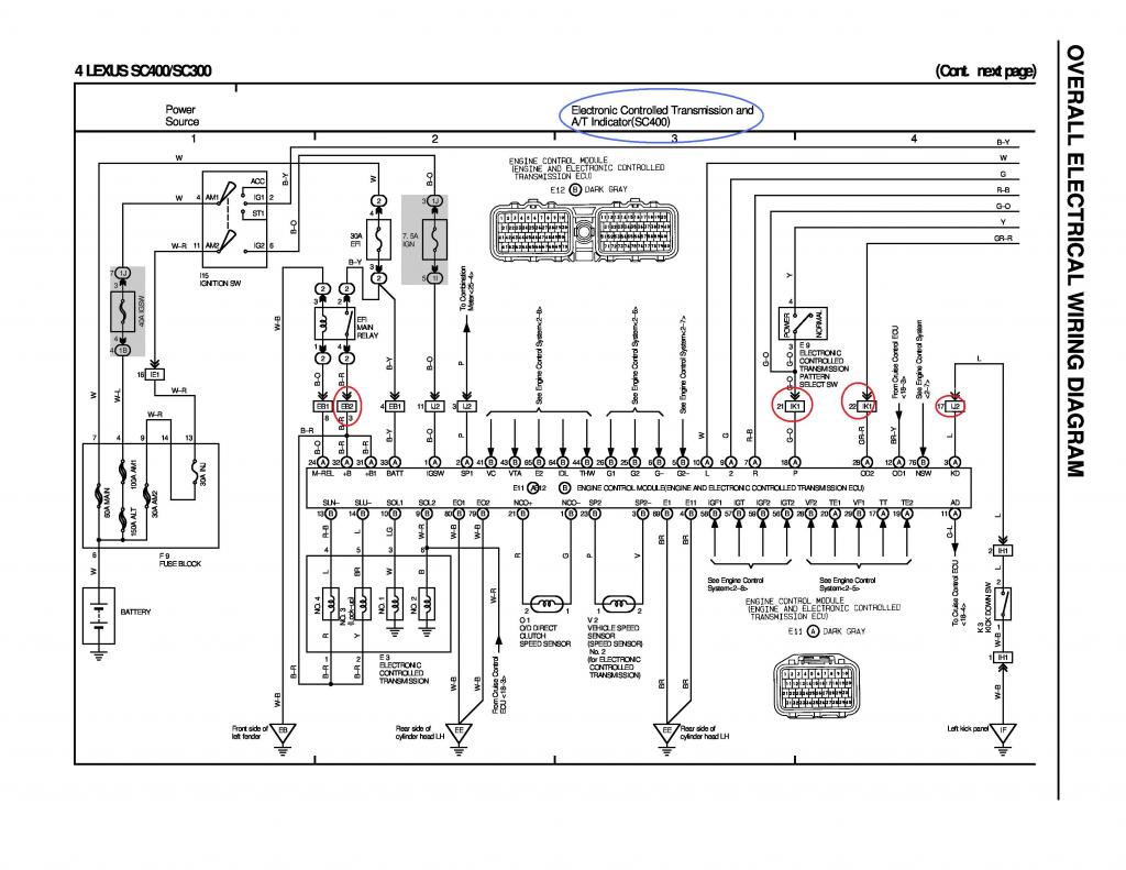
For SC400
EB1
Pin 8 of EB1 goes to Pin 24 of the 40 pin ECU Connector
Pin 4 of EB1 goes to Pin 33 of the 40 pin ECU Connector
EB2
Pin 3 of EB2 goes to Pin 32 of the 40 pin ECU Connector
Pin 3 of EB2 goes to Pin 31 of the 40 pin ECU Connector
Pin 3 of EB2 goes to SLU- / SLN- Pins of the ECT (Pin 2&3 of Transmission Solenoid)
IK1
Pin 21 goes to Pin 18 of the 40 pin ECU Connector
Pin 22 goes to Pin 28 of the 40 pin ECU Connector
IJ2
Pin 3 goes to Pin 2 of the 40 pin ECU Connector
Pin 11 goes to Pin 1 of the 40 pin ECU Connector
Pin 17 goes to Pin 3 of the 40 pin ECU Connector
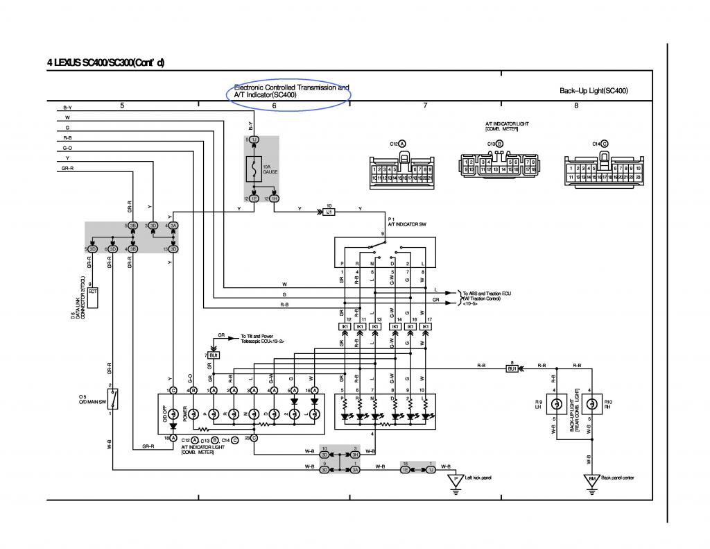
Since you are installing an A340e from a 2jzgte, you cannot use the A/T switch pin numbering on the diagram above. If you go back to the post where we worked on the A/T transmission part of the harness, the A/T switch numbering is different.
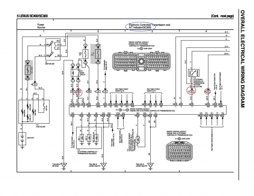
For SC300
EB1
Pin 8 of EB1 goes to Pin 24 of the 40 pin ECU Connector
Pin 4 of EB1 goes to Pin 33 of the 40 pin ECU Connector
EB2
Pin 3 of EB2 goes to Pin 32 of the 40 pin ECU Connector
Pin 3 of EB2 goes to Pin 31 of the 40 pin ECU Connector
IK1
Pin 21 goes to Pin 18 of the 40 pin ECU Connector
Pin 22 goes to Pin 28 of the 40 pin ECU Connector
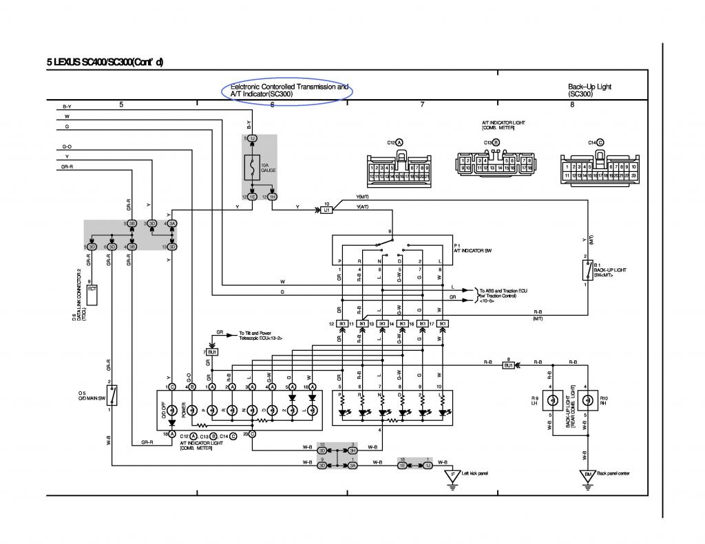
Since you are installing an A340e from a 2jzgte, you cannot use the A/T switch pin numbering on the diagram above. If you go back to the post where we worked on the A/T transmission part of the harness, the A/T switch numbering is different.
Last edited by gerrb; 02-13-19 at 05:30 AM.
#85
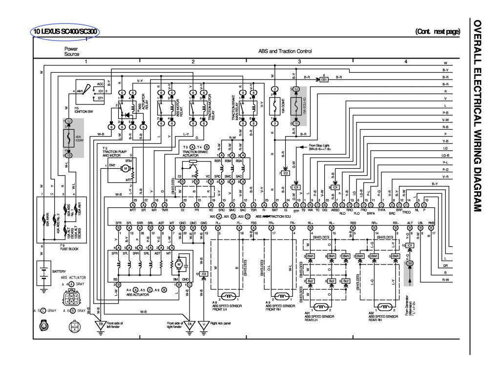
For SC300 / SC400
EB1
Pin 6 goes to Pin 23 of Data Link Connector
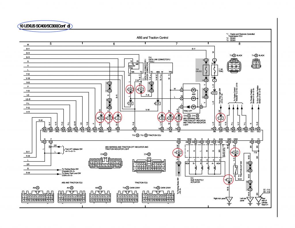
For SC300 / SC400 (only if your car has ABS & Traction Control)
IK1
Pin 10 of IK1 goes to Pin 11 of Data Link Connector and Pin 6 of Traction ECU
IK2
Pin 2 of IK2 goes to Pin 22 of Data Link Connector
Pin 4 of IK2 goes to Pin 14 of T12 Connector
Pin 5 of IK2 goes to Pin 11 of T12 Connector
Pin 9 of IK2 goes to Pin 16 of T13 Connector
Pin 13 of IK2 goes to Pin 1 of T13 Connector
Pin 15 of IK2 goes to Pin 8 of T12 Connector
Pin 16 of IK2 goes to Pin 13 of T12 Connector
Pin 18 of IK2 goes to Pin 15 of T12 Connector
IJ1
Pin 13 of IJ1 goes to Pin 14 of T13 Connector
IJ2
Pin 7 of IJ1 goes to Pin 2 of T12 Connector
Pin 12 of IJ2 goes to Pin 2 of T13 Connector
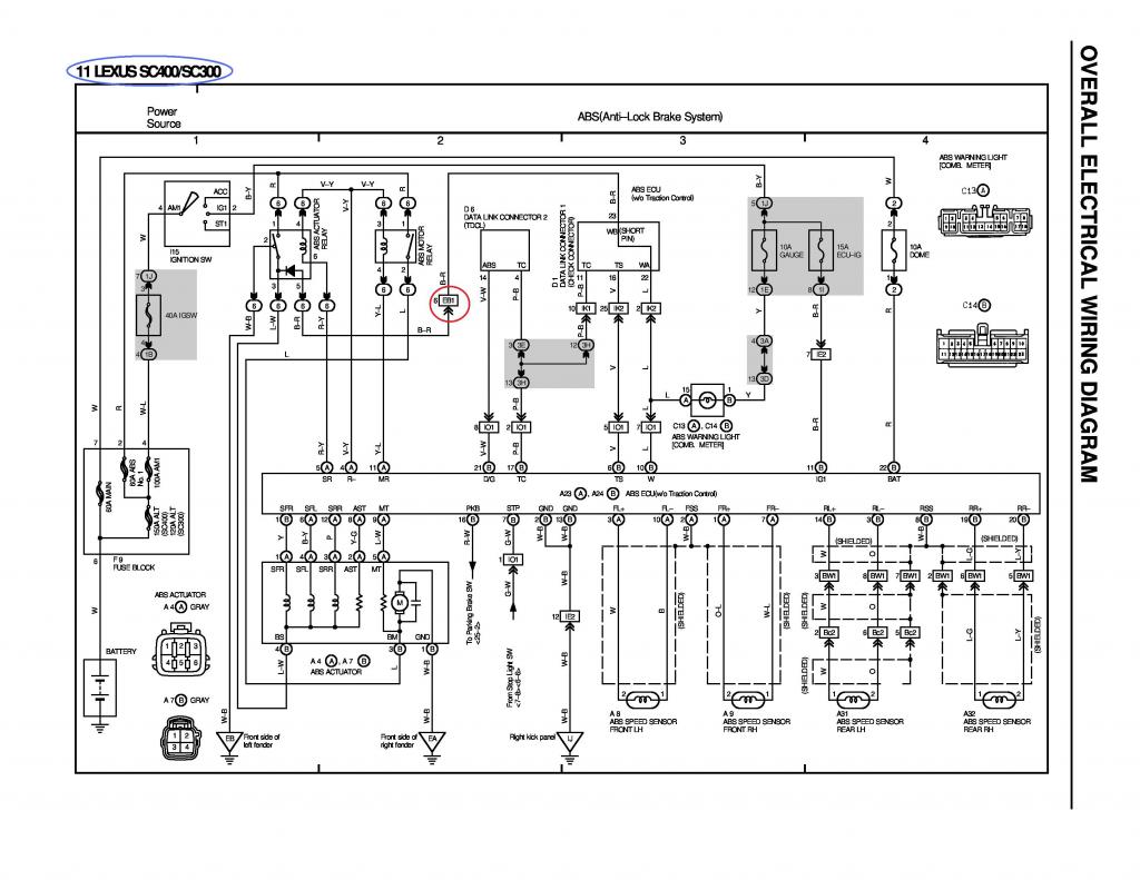
For SC300 & SC400 (for those with ABS)
EB1
Pin 6 goes to Pin 23 of the Data Link Connector
IK1
Pin 10 goes to Pin 11 of the Data Link Connector
IK2
Pin 2 goes to Pin 22 of the Data Link Connector
Pin 25 goes to Pin 16 of the Data Link Connector
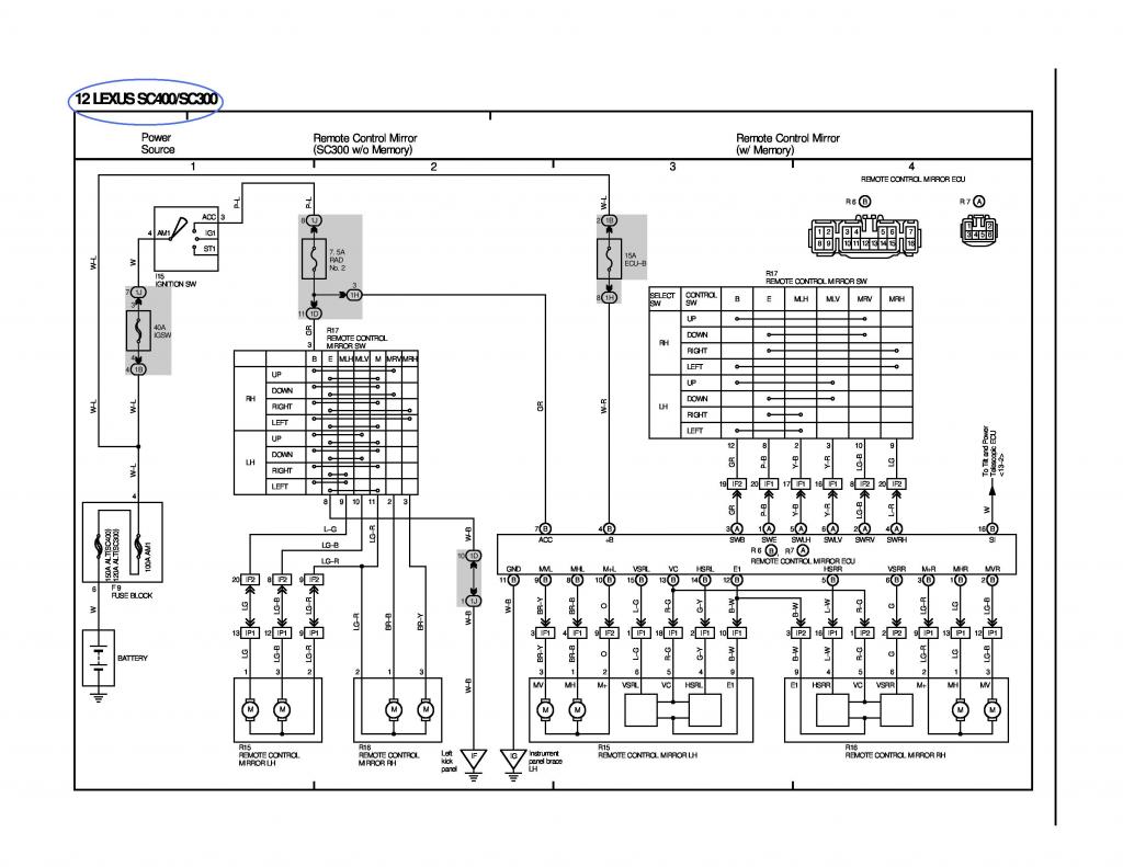
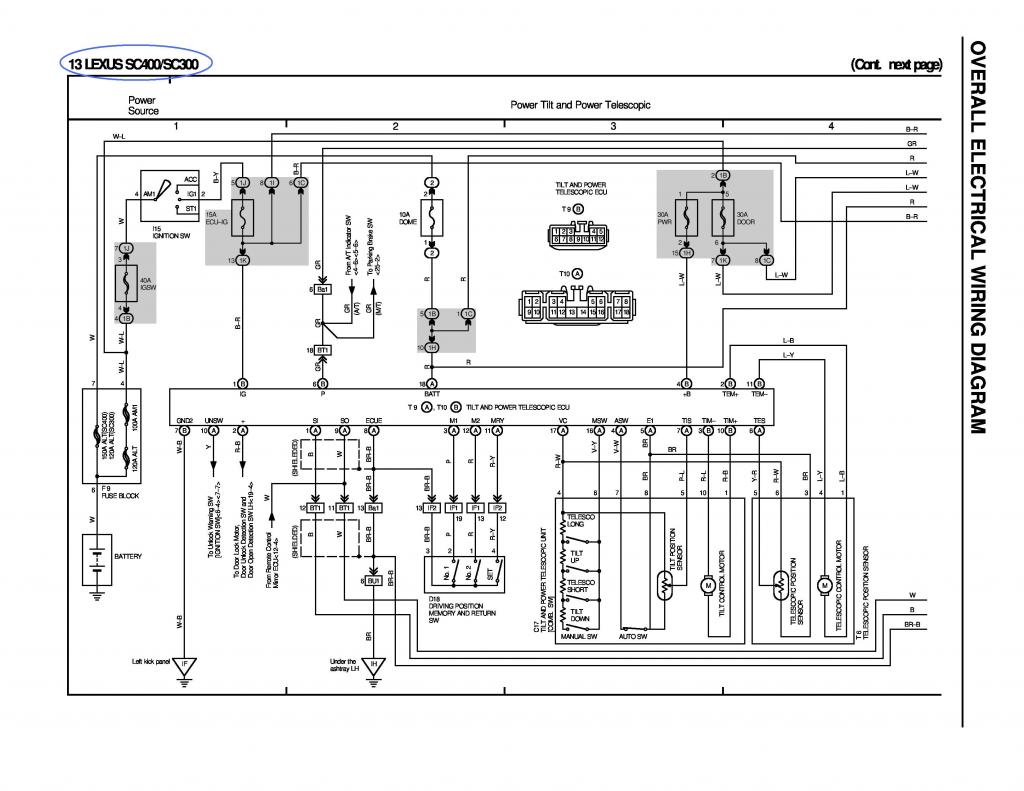
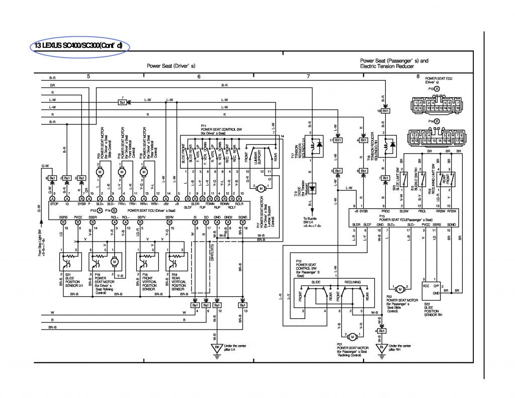
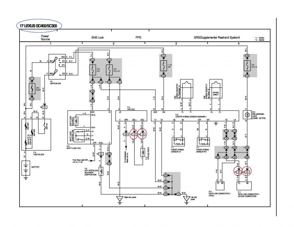
For SC300 & SC400
IJ2
Pin 6 of IJ2 goes to Pin 1 of PPS Solenoid
Pin 16 of IJ2 goes to Pin 2 of PPS Solenoid
IK1
Pin 10 of IK1 goes to Pin 11 of Data Link Connector
Pin 23 of IK1 goes to Pin 5 of Data Link Connector
Last edited by gerrb; 02-05-15 at 04:01 AM.
#86
Lexus Champion
iTrader: (13)
Join Date: Feb 2008
Location: Sacramento
Posts: 2,187
Likes: 0
Received 0 Likes
on
0 Posts
I just want to thank you for such a huge contribution to the forums. Something this detailed is really hard to come by. Everyone who will be following this when they do their swap will save lots of headache and money.
#87
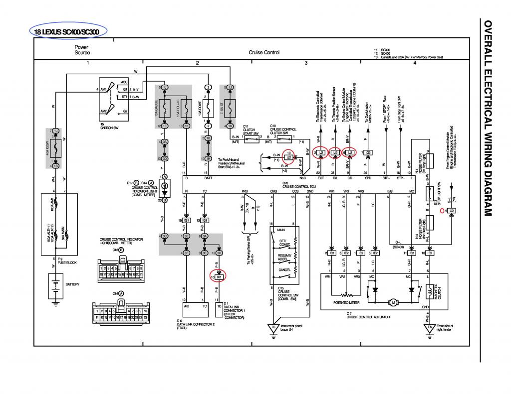
For SC300 / SC400
IJ2
Pin 1 of IJ2 goes to Pin 64 of 80 pin ECU Connector and Pin 2 of TPS
Pin 2 of IJ2 goes to Pin 9 of 80 Pine ECU Connector
Pin 9 of IJ2 goes to Pin 12 of the 40 pin ECU Connector
Pin 10 of IJ2 goes to Pin 6 of IJ1 and to Pin 6 of Park / Neutral Switch
IK1
Pin 10 of IK1 goes to Pin 11 of Datalink Connector
For SC300
Pin 10 of IJ2 goes to Pin 6 of IJ1 and Pin 3 of the Park / Neutral Switch
For SC400
Pin 4 of IJ2 goes to Pin 11 of the 40 pin ECU Connector
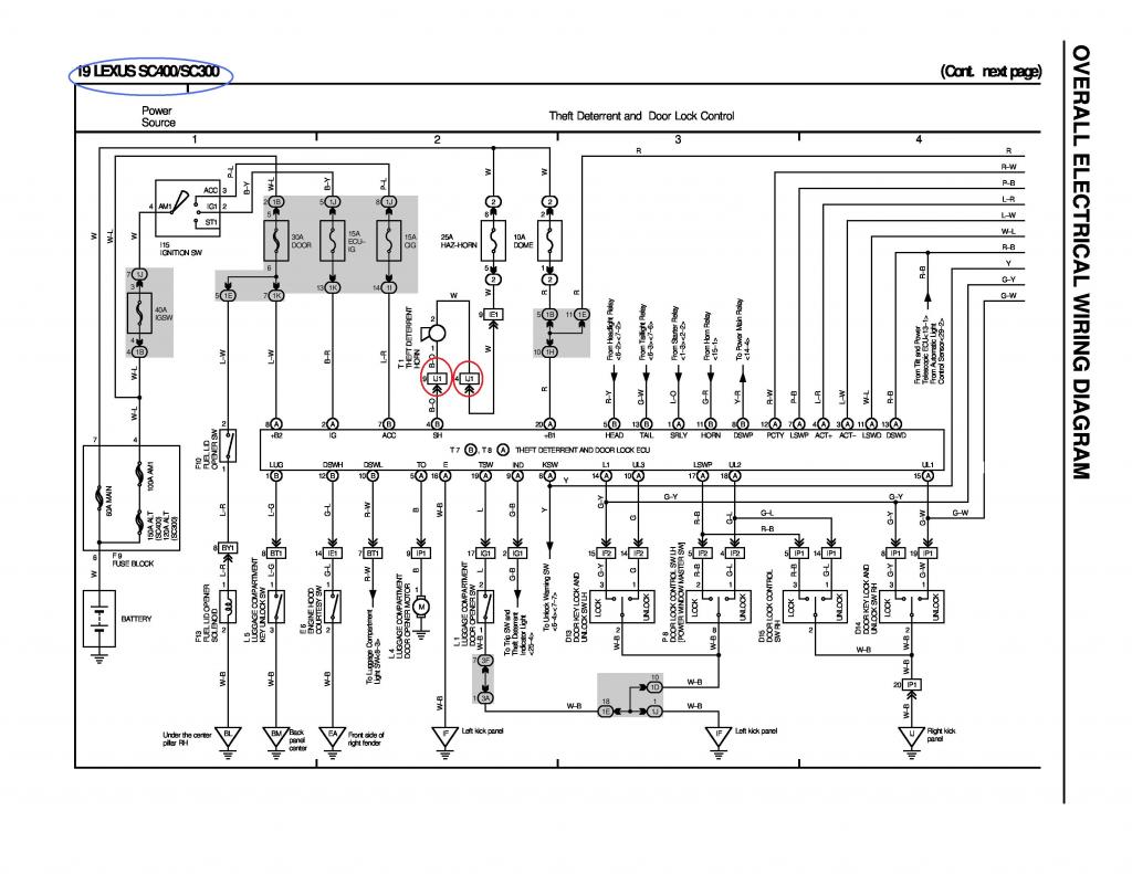
For SC300 / SC400
IJ1
Pin 4 of IJ1 goes to Pin 2 of the Horn Plug
Pin 9 of IJ1 goes to Pin 1 of the Horn Plug
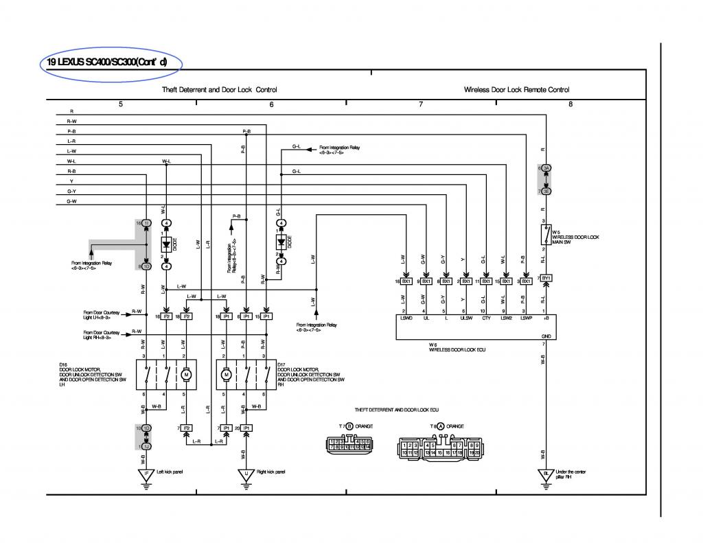
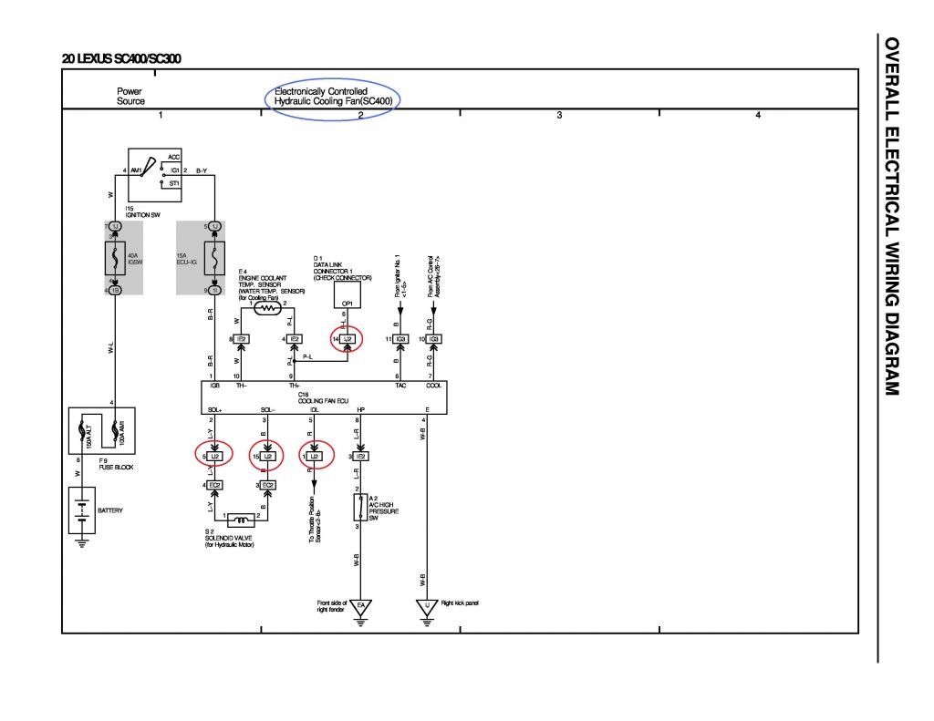
For SC400
IJ2
Pin 1 of IJ2 goes to Pin 64 of the 80 Pin ECU Connector
Pin 5 of IJ2 goes to Pin 1 of Hydraulic Motor Connector (if you want to keep Hydraulic Fan)
Pin 14 of IJ2 goes to Pin 6 of Data Link Connector
Pin 15 of IJ2 goes to Pin 2 of Hydraulic Motor Connector (if you want to keep Hydraulic Fan)
Last edited by gerrb; 03-25-15 at 02:28 PM.
#88

GOT IT
 !!! lmaol.
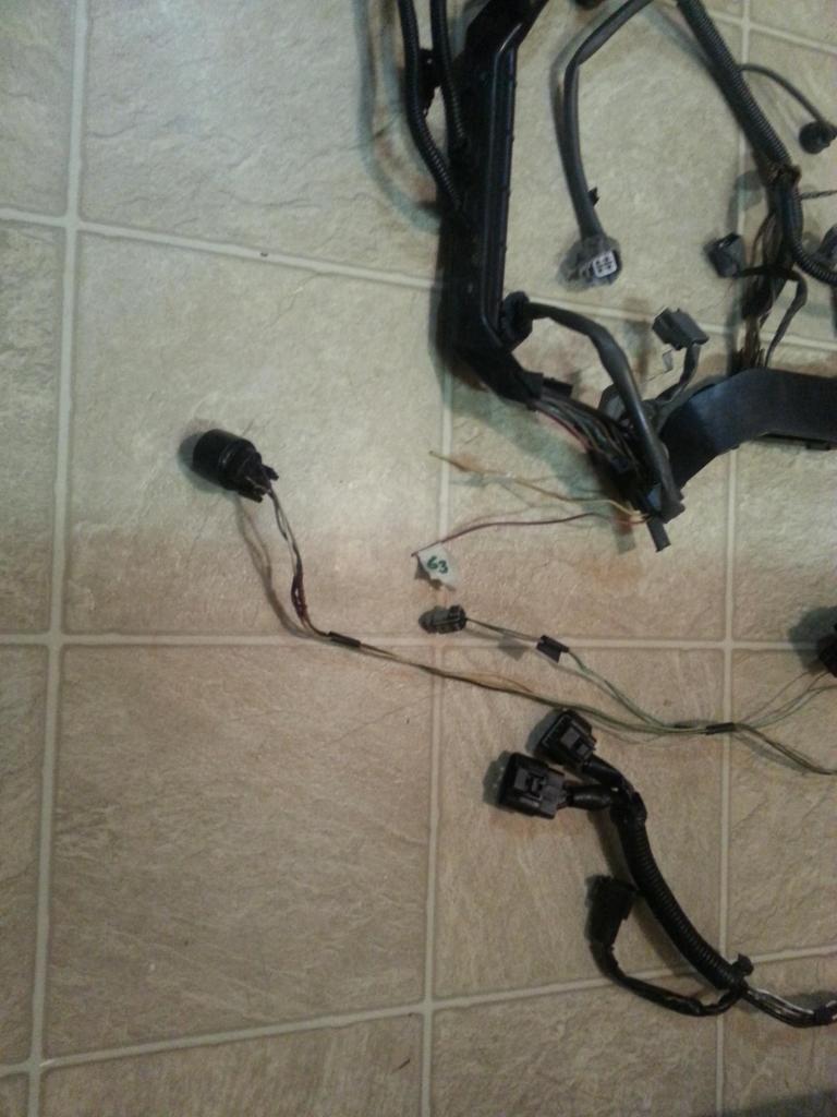
When I was doing the process of elimination on the SC300 harness , I accidentally cut the wires of the 3 pin Connector for the Speed Sensor without checking where the hell the wire goes. If you check back our chart , I just put there GOES TO BODY PLUG .. haha.. cause I didn't know where the wire goes but I knew , once I go through the diagrams one by one searching for what goes to body plugs I will find that sucker and this is it pictured above ! Again the beauty of going through Part IV .. scanning through all those diagrams , you will eventually find what you are missing.
For SC300 & SC400
IK1
Pin 6 of IK1 goes to Pin 2 of the Speed Sensor 1
Pin 7 of IK1 goes to Pin 3 of the Speed Sensor 1
Pin 20 of IK1 goes to Pin 1 of Oil Pressure Switch
IK2
Pin 10 of IK2 goes to Pin 1 of Oil Level / Oil Temp
IJ1
Pin 10 of IJ1 goes to Pin 1 of the Speed Sensor 1
Last edited by gerrb; 08-29-15 at 03:49 PM.
#89
For SC300 & SC400
IK1
Pin 8 of IK1 goes to Pin 1 of Short Connector and to Pin 4 of Igniter (TAC)
Pin 9 of IK1 goes to Pin 1 of Water Temp Gauge Sensor
For SC300
IK2
Pin 24 of IK2 goes to Ground on Front Intake Manifold
Short Connector (6 pins)
Pin 1 of Short Connector goes to Pin 8 of IK1 Connector
Pin 2 of Short Connector goes to Pin 20 of IK1
Pin 3 of Short Connector goes to Pin 3 of IJ1
Pin 4 of Short Connector goes to Pin 3 of EB2
Pin 5 of Short Connector goes to Pin 7 of IJ1
For SC400
IK2
Pin 24 of IK2 goes to Ground of Rear Side of Cylinder Head
Short Connector (3 pins)
Pin 1 of Short Connector goes to Pin 8 of IK1 Connector
Pin 2 of Short Connector goes to Pin 20 of IK1
Pin 3 of Short Connector goes to Pin 9 of IK1
For SC300 & SC400
IJ1
Pin 2 of IJ1 goes to Pin 2 of II1 & Pin 2 of VSV (Water Valve) Connector
EB1
Pin 1 of EB1 goes to Pin 4 of the AC Connector
Pin 2 of EB1 goes to Pin 23 of the 40 Pin Connector
For SC300 & SC400
II1
Pin 1 of II1 goes to Pin 7 of the EB1 Connector & to Pin 1 of the AC Connector
Pin 2 of II1 goes to Pin 2 of the IJ1 Connector & Pin 2 of the VSV (Water Valve) Connector
Pin 4 of II1 goes to Pin 2 of the AC Connector
Pin 5 of II1 goes to Pin 34 of the 40 Pin Connector
Pin 7 of II1 goes to Pin 1 of the VSV (Water Valve) Connector
IK1
Pin 10 of IK1 goes to Pin 11 of the Data Link Connector
EB1
Pin 7 of EB1 goes to Pin 1 of the II1 Connector & to Pin 1 of the AC Connector
Last edited by gerrb; 02-11-19 at 09:11 PM.


