When you click on links to various merchants on this site and make a purchase, this can result in this site earning a commission. Affiliate programs and affiliations include, but are not limited to, the eBay Partner Network.
The COP (coil on plug) ignition coils on 1998-2000 LS400 reside atop 185- 200 F Aluminum valve cover which radiates heat onto and into these components and wiring.
Electronics perform more efficiently and last longer when not operating continuously at elevated temperatures .such as on top of a hot engine.
The wiring harness loom side plastic connector shells do not like such elevated temperatures either....each time it becomes necessary to disconnect a component connector I am confronted with replacing the connector shell.
Accordingly, in order to finish the work in one session, I plan ahead and order connector shells before disconnecting particular components.
All of the COP wire harness side connectors are brittle and have lost their locking tabs because they are cooking atop hot valve covers...
To Toyota's credit, these connectors are readily available...but the 1990-1994 LS400's used rubber shrouds over many of their engine bay connectors and work like new
So, it seems logical that insulating these 8 coils from direct engine heat will yield benefits in increased coil performance.and efficiency resulting from lower operating temperature...such as lower coil resistance...
Side profile of right valve cover with COP. My guess is the valve cove triangle shaped ridge on right is deflect rising exhaust heat away from coils. Top profile of the valve cover...Polishing the Aluminum cover would reduce surface area thus amount of radiated heat...
While it would also improve the appearance, not sure impact on engine cooling...
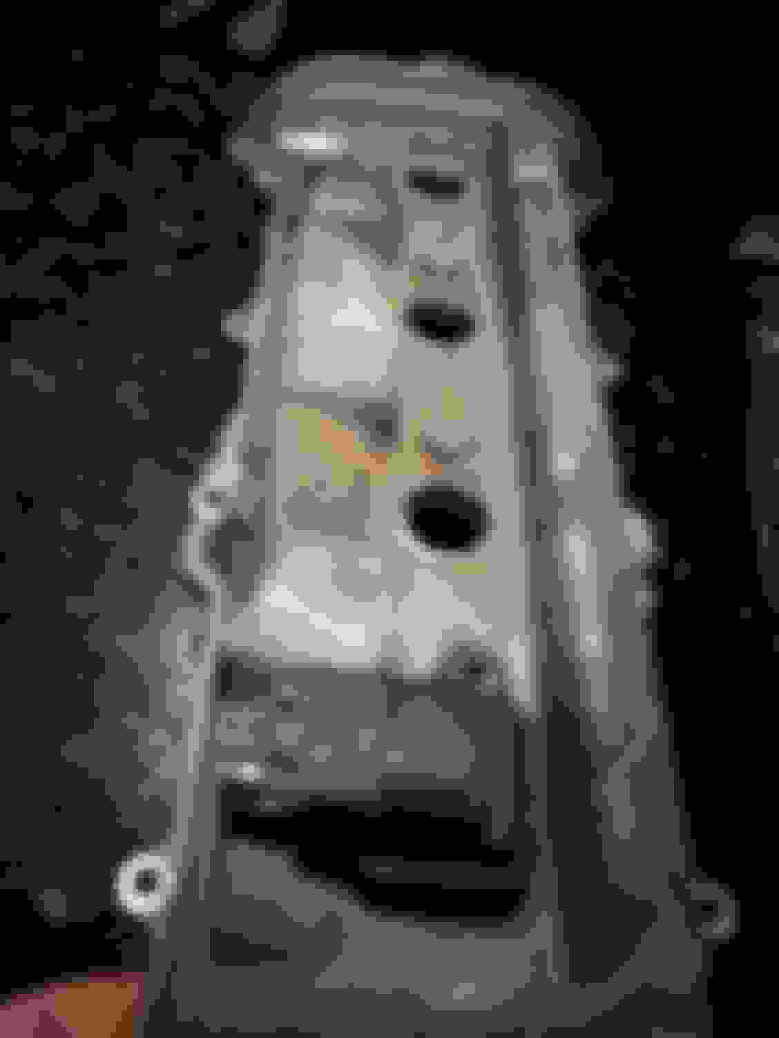
Another way is towards thermal management is to insulated the valve cover COP valley to block radiated heat from reaching the coils. Raw sample of DEI
Performance Products 3/16" heat barrier shown.
Another image depicting DEI heat barrier at bottom of coil valley. DEI's material incorporates 600 F high tack pressure sensitive adhesive... A single piece would easily be patterned to fit the entire valley.
bottom of valley has tapped bosses for mounting coils which are about 3/8" high so plently of space below coils. DEI Heat Barrier Composite composition
Use coils mounted else where and in a cool location, and run good old wires to the plugs. I bet a place like MSD would have something.
Now that is a project for another day, meanwhile am spending $10 for thermal insulating material that presents incremental improvement within the framework of the existing ignition system
how expensive are each one of those coils to replace if they go bad? It makes me glad that I have the older 97 model which uses two main coils in front w/ caps and rotors.
how expensive are each one of those coils to replace if they go bad? It makes me glad that I have the older 97 model which uses two main coils in front w/ caps and rotors.
Not inexpensive but better, more consistent performance than rotorrs, caps, spark plug wires...which degrade through use and time
1998-2000 LS400 uses COP ignition scheme.
The coils reside atop the COP assembly whereas "pencil" type coils employed on 2001-2006 LS430 reside inside the spark plug tubes to bake.
The pencil type coils are not as durable as coil near plug configuration.
Am pursuing this project in earnest as to the best approach for employing thermal insulating materials in an effort to reduce coil temperatures.
The coil on LS400 is face mounted to a 200 F + Aluminum valve cover, clamped in place with steel fasteners, so there is the issue of thermal isolation between these components.
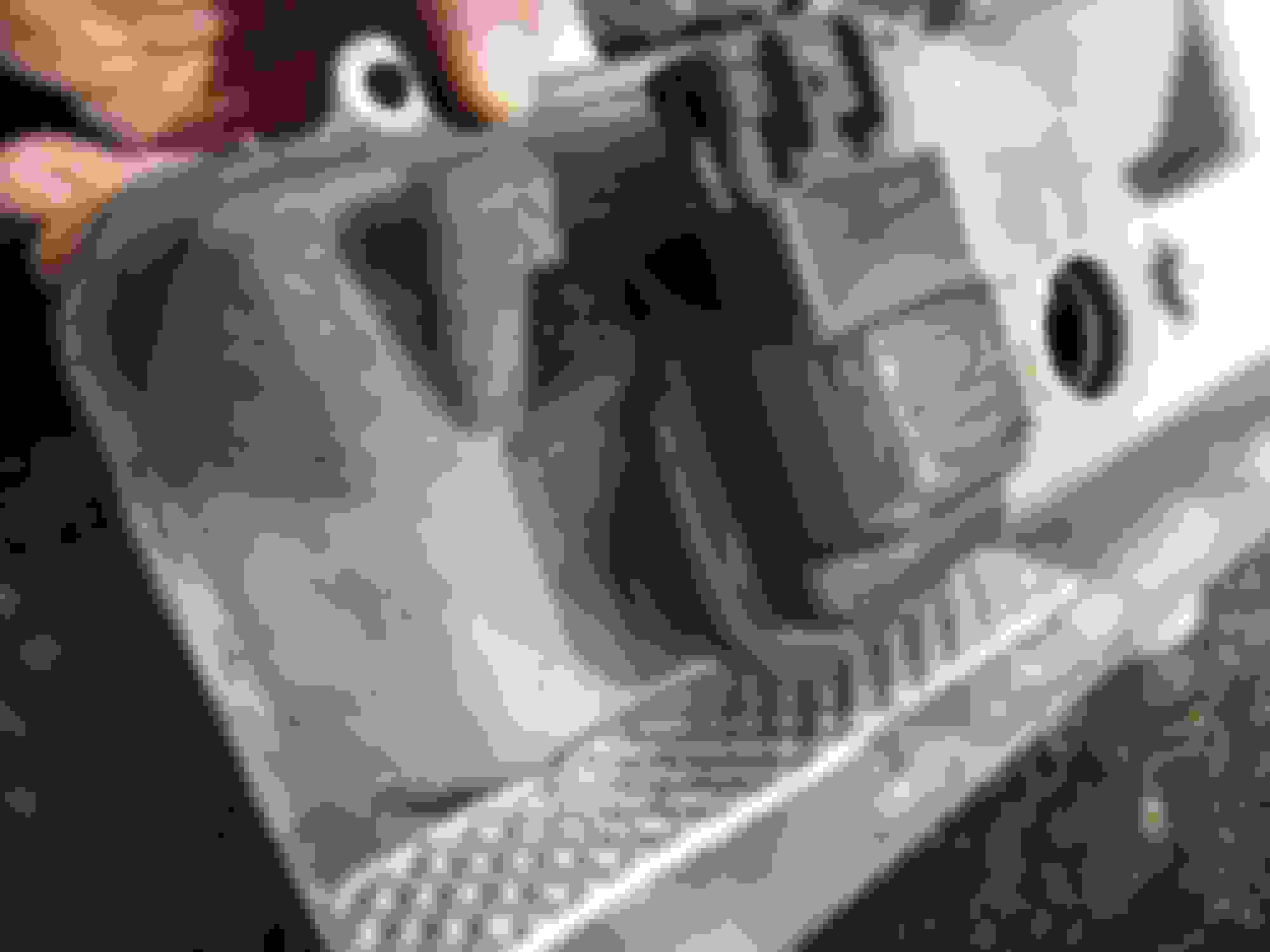
DEI offers heatshields for Corvette coilpacks (coilpacks employ sparkplug wires) which thermal isolation helps alleviate heat soak. Corvette ignition coil heat shields. Spark plug wires not depicted. These are double-sided Aluminum with foam embedded in between.
Here, due to clearances depicted above, the insulating material would need to rest flush to the valve cover face.
The balancing act then is to insulate enough of the coil for maximum effect while minimizing insulating of valve covers...
Coils can be thermally insualed from the fasteners with two 1/32" Teflon washers at each station.
Acquired a set of high performance plastic fasteners that further prevents heat from wicking up from valve cover into coil housing.
Appreciate input from anyone who has worked a solution.
Thanks.
Text from article in link above:
Ignition coils -- What every tech needs to know
June 16, 2011 � by Jim Anderson The process of burning fuel and air powers most of the vehicles in the U.S. and around the world. At its most basic level, this combustion is a chemical process. The burning of fuel and air requires first that the two gasses be mixed, compressed and then ignited by the addition of heat.
The required heat can come from a number of sources. In a diesel engine, the burning reaction is started by the heat caused as the mixture is heated by very high compression. In a gasoline engine, ignition is usually accomplished by an electric spark that is made to arc or jump across the spark plug�s terminals. It is the current of the spark, flowing through the resistance of the gap, which causes the heat needed to start combustion.
The required heat can be delivered in other ways; Ford, for example, has been experimenting with an engine that uses laser beam energy to start the combustion process. Very early engines, built before the invention of the ignition coil, used hot tubes or even flames to start the combustion. The point is that this heat has to be added at exactly the right time and in the right location for greatest engine efficiency. Every technician needs to know how this works.
The business end of a spark plug
Understanding ignition systems, and how they really work, begins with a look at the business end of a spark plug. For typical spark plugs, there is a single center electrode and a �J� shaped ground electrode. Depending upon the polarity of the voltage applied, it is possible for the arc to travel from the center electrode to ground or the other way around. Usually, it is the center electrode that is made negative. This way the spark travels to the center electrode from the ground electrode.
Normally there is not a conductive path between center and the ground electrodes. The goal of the ignition system is to create that conductive path through the air or whatever else is between the electrodes. The molecules of air cannot normally support conduction because the outer layers of their atoms/molecules have no free electrons. To make the air conduct requires a voltage that is high enough to literally rip the electrons loose from atomic forces that are holding them. This process is called ionization.
It takes not only high voltage, but a concentrated high voltage to accomplish ionization. This is where the design of the spark plug and its electrodes becomes important. In order to concentrate the high voltage, sharp edges must be present. When the plug is new, the center electrode is a perfect cylinder with a flat top. The top edge of that center electrode is sharp and helps to concentrate the voltage. The metal shield on this GM coil shields the coil�s magnetics from eddy-current losses that might occur in the metal of the engine. It also serves to protect the coil from excess engine heat.
(All coil photos by Mike Mavrigian.)
In current technology there are two things that can be done to improve the performance of the spark plugs. The first is to go to smaller, more pointed electrodes through the use of very high temperature metals like iridium. Sometimes called �fine wire� plugs, these spark plugs have center electrodes that are half the size and diameter of ordinary plugs
[PAGEBREAK]
The second thing is to add platinum tips or pads to the ends of the electrodes. Platinum is inert at combustion chamber pressures and temperatures. This metal virtually eliminates electrode wear as a consideration. The only reason to replace a plug anymore is if that plug has been contaminated or fouled (usually by a very rich fuel condition) and can no longer fire properly.
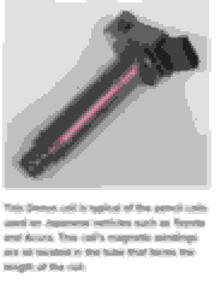
There are a number of factors you need to know in terms of what kind of voltage it will take to jump the spark plug. The first is the shape of the electrodes as noted above. Worn, rounded spark plug electrodes aren�t capable of efficiently focusing the high voltage. As a result, it takes more voltage to fire worn plugs. This Denso coil is typical of the pencil coils used on Japanese vehicles such as Toyota and Acura. This coil�s magnetic windings are all located in the tube that forms the length of the coil.
Other factors include the nature of the materials between the plug electrodes. This can be more complicated than you might think. For the typical spark plug there is a ceramic cone that supports the center electrode and serves to separate the center and ground electrodes. This ceramic can be contaminated with fuel, fuel residue or oil that gets past the rings or valve stem seals, and combustion by-products. While not a problem in a healthy engine, shunting deposits do represent an alternative path for the high voltage that could cause a misfire.
One of the design features of the spark plug is that this ceramic is designed to reach a set operating temperature or �heat� during the normal operation of the engine. The reason for this is to burn off those contaminating residues on the ceramic.
One of the advantages of current technology ignition systems is the speed at which the coil goes from 0 to the required firing voltage. The faster this happens, the more likely the arc will occur across the electrodes and not through any spark plug deposits. The change-over to lead free fuel has also helped by greatly reducing spark plug deposits. An engine that is in a poor enough condition that spark plug fouling is a concern should be considered for rebuilding or replacement.
You would expect that the principle gases in and around the spark plug would be fuel and air. While this is true for the most part, in some cases it is not correct. When the gases in the area are contaminated, the voltage needed to jump the spark gap can be affected. The principle sources of contamination are EGR valve flow and poor volumetric efficiency. Coil packs such as this Ford unit use double-ended coils. This means that one plug will fire negatively and the other positively. This affects where the platinum disc needs to be on the spark plug.
The term �volumetric efficiency� refers to how well the cylinder fills on each intake cycle. The cylinder has a known displacement depending on the size of the original engine design. Gasses flowing in and out of an engine have inertia. They don�t start moving as soon as the intake valve opens, nor do they want to stop moving the moment the valve closes. In some engine designs there is an overlap period between when the intake valve opens and when, finally the exhaust valve closes. The effect is most noticeable at idle. The result for the ignition system is that sometimes what is really flowing in and around the spark plug electrodes is a mixture of fresh air, freshly evaporated gasoline, un-evaporated fuel droplets and possibly exhaust gas. It is also possible to have contaminants such as water, water vapor, antifreeze, and even stale, non-volatile gasoline.
The solution for this is to have a duration or life to the spark. In most ignition systems, once the spark jumps, the electrodes will continue to burn for at least 1,000 microseconds and maybe more. The idea is to keep the gap lit up long enough to ensure that some volatile fuel and air will be ignited.
The required spark plug firing voltage is also affected by the pressures inside the cylinder. The pressure results from compression and also from heavy loading of the engine. The largest firing voltages happen typically in snap throttle acceleration conditions. The change in engine speed, the change in fuel ratio, and the load on the engine contribute to the higher required voltage.
[PAGEBREAK]
Types of ignition coils
Current technology coils are of several basic types. Pencil coils are typically an inch in diameter and up to four inches long. These coils are designed to fit in between the cams of DOHC and SOHC engines. The normal practice for pencil coils is to include the switching electronics needed to control the coil, in a small pocket near the outer end of the coil package.
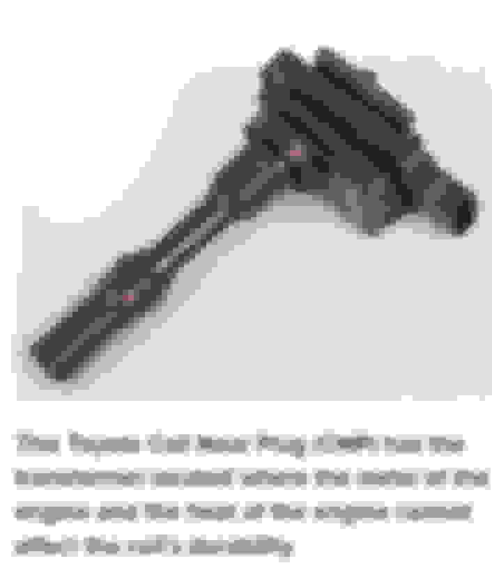
Pencil coils have the advantage that they are made to fit within the small area available between the cams. While they package very well on to the engine, pencil coils have the disadvantage of their location. That part of the engine typically operates at very high temperature. The metal surrounding the coil can interfere with the magnetic action of the coil, reducing its output. This is a major consideration in direct injection engines. Pencil coils are also more expensive to manufacture, and possibly less reliable in actual use, than conventional coils. This Toyota Coil Near Plug (CNP) has the transformer located where the metal of the engine and the heat of the engine cannot affect the coil�s durability.
Coil Near Plug (CNP) applications use a short, plastic insulated stick or a rubber spark plug boot to reach down into the engine and the spark plug. This keeps the transformer portion of the coil up and away from the metal of the cylinder head. While CNPs do not package as neatly as pencil coils, their operating temperature is lower and thus their reliability is greater. CNPs are perhaps one-third less expensive to manufacture than comparable coils. Some CNPs include integrated electronic packages while others do not.
Still in use on some engines are the coil pack type ignition coils. Inside the coil packs are double ended coils that can be connected to simultaneously fire the plug for one cylinder under compression and also a second cylinder on its exhaust stroke. The spark that occurs on the cylinder under �exhaust� is a wasted spark that serves no purpose. Still, this arrangement allows a single coil pack to serve a pair of cylinders. On the next rotation of the engine, what was a wasted spark will become a useful spark when that cylinder is under compression. This is Ford�s Coil On Plug (COP). The distance between the coil and the top of the spark plug is filled with a rubber boot. Inside the boot is a spring that contains a special slug of ferrite designed to reduce ignition system noise.
The disadvantage of coil pack type systems is that they still use spark plug wires and boots to conduct the spark from the coil to the spark plugs. Spark plug wires and boots have long had warranty-related problems and are being design-eliminated from most current technology engine designs. Coil packs are also comparatively big and heavy as compared to CNPs.
There are still millions of road vehicles and agricultural vehicles that still use a distributor, distributor cap, rotor and spark plug wires. With this type of system, cylindrical, oil-filled coils may be used. In this type of system, the coil is designed to supply sparks to as many as eight cylinders. The cap and rotor act as a high voltage switch that distributes the output of the coil to the required spark plug. The cap, rotor and spark plug wires are all subject to wear and contamination issues. Also, the coil in this type of original-equipment system doesn�t have time to store a full amount of spark energy for every combustion event. The net result is that these systems have lower output voltages and lower reliability than the newer systems that replaced them. Typical to Japanese-made CNPs, this hard plastic tube features soft boot material at each end. The large doughnut on one end serves to keep moisture out of the spark plug well. The doughnut must be vented to allow vapors and gasses that leak past the spark plug to escape. Ignition coil construction
The basic construction of an ignition coil begins with two coils of wire. The primary consists of approximately 100 turns of what is called magnet wire. Really, there is nothing special about �magnet� wire other than being intended for the making of electromagnetic assemblies such as transformers or coils. For the typical ignition coil, the primary is a single strand of copper wire of approximately 22 gauge. The wire is insulated with a thin layer of polyester insulation.
This insulation allows the primary to be wound into a coil shape (to maximize inductance) without the individual turns shorting out to their neighbors. Winding the coil in a circular, tube like shape helps to concentrate the inductance.
The secondary of the coil is typically wound on to a plastic bobbin that has been divided into sections or bays. The wire used in the secondary is much finer than the primary wire. This too is magnet wire. Typically, this type of wire is a single strand, 42 to 44 gauge wire that is coated with a dozen or more very thin layers of insulation. For comparison, this wire is smaller in diameter than the average human hair. It depends on the type of coil being made, but as many as 10,000 turns of the fine wire is wound onto the secondary bobbin. The secondary coil will have a resistance of between 6,000 and 10,000 ohms. The primary coil mounts inside the secondary coil. Stretched out, there might be as much as half a mile of wire wound onto the secondary bobbin. Many coil designs use a magnet in the circuit. The magnet can be seen here where the T lamination joins the C-shaped lamination. The magnet increases coil output while also reducing coil size.
Inside both the primary and the secondary coils is the lamination stack. The lamstack can be 20 to 30 layers of thin electrical grade steel that is laid out in a rectangular path. Often, two �C� or �U� shaped pieces are made so that they can be assembled, face to face, with one side routed through the primary and secondary coils. The two C�s do not quite make a full path. A gap of roughly 1mm (0.039 inch) is left in the otherwise rectangular path. This gap is important to the storage of magnetic energy in the primary of the coil.
[PAGEBREAK]Making the stack out of so many layers of steel has the purpose of breaking up eddy current losses that would otherwise limit the output of the coil. Some coils use a very special powdered metal whose particles are insulated with plastic to form the magnetic core of the coil. The coil primary is 100+ turns of heavy wire wrapped in this case on a plastic bobbin. The lamstack will fit through the square hole in the center.
Once the coil pack is made, it is necessary to fully impregnate the coil with epoxy resin. The resin is forced under pressure into every nook and cranny of the coil. The resin serves to insulate, and capture the high voltage inside the operating coil. The epoxy also serves to keep moisture out of the coil and to distribute the heat that is created while the coil is in normal operation. The downside to the epoxy is that it is relatively brittle and can crack during severe thermal cycling of the coil.
How the coil actually works
In actual use, one side of the primary coil is connected to the positive side of the vehicle battery. The opposite end of the coil is connected through an ignition coil driver transistor to ground. When the driver is turned �on,� current will start to flow in the primary coil.
With a battery supply of 14.0 volts, and a primary resistance of 0.5 ohms, by Ohms law it would seem that a current of 28 amps would flow. This is not the case for several reasons. The first reason is that the primary current flow is limited and opposed by the inductance of the primary coil. As viewed on an oscilloscope, the current rises at what looks like about a 45 degree angle to about 7 amps. The current, working with the primary coil inductance, stores energy in a magnetic field that surrounds the primary coil. It varies, but the dwell time needed to store energy in the coil primary is usually between two and four milliseconds.
The engine computer will know in advance when it wants a spark from the coil. The target is to start the dwell period enough in advance of spark event for the primary coil current to reach full energy storage. This time depends somewhat on battery voltage and more on the exact internal temperature of the ignition coil. This may be harder to predict. For this reason, most coil electronics include a coil current limiting feature. When the target current level is reached, the coil driver transistor is turned partially off, limiting any further rise in the current. The goal is to keep the coil current limit time as short as possible to avoid excess heating in the coil driver. The coil limit time can be seen as a flat portion that comes after the 45 degree ramp of the charge curve, and just before the spark event.
The turn-on and dwell of the coil is controlled by a square wave pulse from the engine control computer. The rising edge of the square wave turns on the coil driver, beginning the dwell period. The time the pulse stays �on� represents the computer�s command for coil �on� time or dwell period. When the computer pulse drops back to zero, the driver is turned off and the current ceases to flow in the primary coil.
When the coil primary current is turned off, the energy stored in the magnetic field around the primary coil will collapse back into the coil that created it. It is this collapsing magnetic field that induces into the primary coil windings a flyback voltage of approximately 400 volts. The difference is in the speed of the collapse. The faster the magnetic lines of force are moving, the greater the voltage that will be created in the primary coil. It is the collapsing magnetic field that creates the 400 volt pulse in the primary coil. This is a Delphi coil pack for General Motors. This Delphi coil features three separate coil packs in a single package called a cassette. While the cassette does provide nice engine compartment packaging, it does mean that all three coils must be replaced if only one coil fails.
This primary pulse is transformed between the primary and the secondary. The approximately 100 to one turns ratio, (secondary to primary) means that the voltage will be stepped up to 100x 400 or approximately 40,000 volts at the output of the secondary coil.
Of course there is something of a trade-off here. While the voltage was stepped up from primary to secondary, the current is stepped down. Typical secondary currents are in the milliamp range. However, this is enough to create the heat that starts the burning reaction.
Some coils use a rare earth magnet embedded in the laminations to improve coil performance and reduce coil size. The magnet biases the lamination of steel in one direction.
The primary coils magnetic field pulls the magnetic field in the opposite direction against the magnet�s field. When the primary current is turned off, the field collapses. Because the steel was biased by the magnet, the resulting change in magnetic flux is much greater. The increased flux change results in a higher coil output for a given size.
[PAGEBREAK]
Coil operation on the vehicle
Even though the coil may be capable of an output of 40,000 volts, this almost never happens in real life. What will happen is that the voltage will rise as high as it takes in order for the spark plug gap to ionize. Based on the variables discussed earlier, the voltage required could be as low as 3,000 volts or as high as 30,000 volts.
The lower voltage can be enough to ionize the gap under high speed, light load conditions. The maximum required voltage happens under heavy acceleration where the load is high and the fuel mixture is rich.
Typical ignition firing voltages are between 8 kv and 22 kv. Having a higher voltage available from the coil may not be an advantage. Spark plug wires, boots, caps and rotors can be damaged by excess voltage. If the plug has not fired by 30 kv, the connection may have been lost either internally or externally.
As the voltage increases further, and has no place to go, it may jump out of the side of the boot, the spark plug wire or even the coil package itself.
Allowing the coil voltage to rise too high often results in system damage.
Typical ignition coil waveforms
By far the best tool for diagnosing ignition coil problems is the oscilloscope. On some coil designs it is possible to measure the primary and secondary coil resistances from outside of the coil. The primary resistance is a low value (typically 0.5 ohms) and is difficult to measure accurately even with a digital ohmmeter. While it is possible to measure the secondary resistance, the answer you get might really not tell you very much. The coil�s resistance is quite sensitive to the actual temperature inside the coil. The temperature related change might effectively �hide� the resistance change caused by shorted turns in the coil secondary. Even a small percentage of shorted turns can dramatically reduce the available coil output voltage. Figure 1�This is a basic charge curve wave form. The slope is caused by the inductance of the primary opposing the rise in current. The flat spot at the top is coil current limiting. (All screen photos courtesy IATN.)
There are three distinctive coil waveforms that define the performance of the coil. The first is the coil primary current waveform (see Figure 1). A properly operating coil will have a smooth, linear change from 0 amps at the start of the dwell period to whatever value the car maker determined was required for a full energy spark. Please remember that some coils will show a flat area at the top of the ramp that represents coil current limiting.
[PAGEBREAK] Figure 2�This is input pulse from the engine�s control computer. The rising edge turns on the coil driver. The time of the pulse from start to finish is the �dwell� or energy storage time. The falling edge is the command to �fire� the ignition coil.
The coil primary voltage (Figure 4) is the 400 volt flyback voltage spike that occurs when the coil current is turned off. The amplitude and shape of the waveform indicates not only the value of the spike but the ability of the coil to oscillate after the initial spark. In a normally operating coil, energy oscillates back and forth producing damped sine waves. Figure 3�This curve shows a Ford multi-spark system. At idle, it may be useful to have a longer spark duration. This system partially re-dwells the coil and then fires a second and third lower-energy spark. If the fuel and air have not begun combustion by the time of the added sparks, the main benefit will be to prevent unburned gasses from entering the catalytic converter.
These sine waves are a good indication of the �Q� or the quality of the coil and its ability to freely exchange energy. Shorted turns and other quality problems with the coil are more readily apparent on an oscilloscope.
A key point to make here is that the primary coil and the secondary coil surround the same lamination stack. This means that what is seen in the primary waveforms is an indication of what could be going on in the secondary or vice versa. Shorted turns in the secondary are often seen in the primary current waveform. When you have that circumstance, the waveform will step up vertically for maybe one or two amps before it takes off at the usual 45 degree angle. Figure 4�The primary voltage waveform shows an initial spike of about 400 volts. The voltage then falls to represent the �maintain� voltage seen in the secondary across the spark gap. It is this spike that the transformer turns ratio converts into the voltage needed to bridge the spark plug gap.
Most techs do not have the needed high voltage probe to look directly at the secondary waveforms. The good news is that usually such a measurement is unnecessary. The faults that may occur in the secondary are often visible in the primary waveform.
[PAGEBREAK]
Ignition coil failure modes
As noted, there are several different types or styles of ignition coils. Each has their own construction difficulties and possible failure modes. The most common failure for the setting of a MIL or trouble code indicates a particular cylinder is misfiring (indicating that the combustion event did not happen). This can occur at very low levels in a normally operating engine. The trouble code is set when the percentage of misfires rises above the standards set by the manufacturer. This might be a rate of about 0.1% of the combustion events.
The lack of combustion may be due to a spark plug defect, a coil defect or a defect in the boots or wires associated with that cylinder. A very common problem involves spark plugs. When the connection to the spark plug opens or the plug becomes un-fireable, the voltage from the coil will rise. Oftentimes this will create a breakdown in the insulation of the spark plug boot or wires. This results in an arc that passes through the side of the boot and nails the nearest point at ground potential. Once an arc has occurred, the pinhole created by the arc represents permanent damage to that boot.
The next high voltage pulse will pass more easily through the pin hole further damaging the boot. When it gets bad enough, the arc will occur first even though the spark plug has been restored to normal firing condition. The solution is to replace the damaged boot and damaged spark plug. The coil has really not failed.
As noted above, coils are made of numerous materials including copper, steel, plastic and possibly brass or aluminum. Each of these materials has a different coefficient of thermal expansion. As the coil heats and cools in normal operation, these coefficients work against each other. These forces effectively try to tear the coil apart. The visual damage is often seen as cracks in the epoxy or housing. The reduced diameter electrodes of the fine wire spark plug have two benefits. The first is that they help concentrate the high voltage, making it easier to bridge the gap. Secondly, the fine wire plug, and its concentrated field, also help to prevent spark blowout in high swirl applications such as GDI.
Coil failures can also be the result of shorted windings in either the primary coil or the secondary coil. If the coil driver fails, it may not be able to limit the coil primary current to safe levels.
The primary is not designed to handle anything like 28 amps. The heat which that amount of current will cause will surely melt and destroy the primary coil if it is allowed to happen.
Other possible failure modes include mechanical damage to the coil itself or the electrical connections to the vehicle wire harness. Coils with obvious mechanical damage such as broken or cracked connectors or high voltage towers should be replaced.
There is no wear-out factor in the coil itself other than thermal cycling and the damage it may cause. Boots and wires do age, resulting in reduced insulation value over time. The key to correct ignition system diagnosis is to understand the details of how the system you are working on really functions.
I came across your excellent writeup and, if you don't mind, I have a quick question/confirmation i'd like your view on about driving the COP denso coils:
If I connect pin4 to +12v on ,pin1 to GND and pin2 (IGT) to 5V and pin3(IGF) thru a momentary switch to GND, will that allow me to generate a spark when pushed?
In effect, i guess I'm asking how to drive the COP coil and spark plug independent of the car's system
I'm not looking to do this on the car, but rather to reuse some of the still working coil/sparkplug I recently replaced as an igniter for a foundry. It's common to use the old style ignition coils for that but I have not found anyone describing the use of a COP coil. Given it's small and somewhat self contained, it seem ideal.
Hope you get to see this, Sorry if i posted it in the wrong place, i don't know the site very well.
Last edited by paddua; 05-05-21 at 04:07 PM.
Reason: typos
 10-22-17, 10:20 AM


 The process of burning fuel and air powers most of the vehicles in the U.S. and around the world. At its most basic level, this combustion is a chemical process. The burning of fuel and air requires first that the two gasses be mixed, compressed and then ignited by the addition of heat.
 The metal shield on this GM coil shields the coil�s magnetics from eddy-current losses that might occur in the metal of the engine. It also serves to protect the coil from excess engine heat.
 This Denso coil is typical of the pencil coils used on Japanese vehicles such as Toyota and Acura. This coil�s magnetic windings are all located in the tube that forms the length of the coil.
 Coil packs such as this Ford unit use double-ended coils. This means that one plug will fire negatively and the other positively. This affects where the platinum disc needs to be on the spark plug.
 This Toyota Coil Near Plug (CNP) has the transformer located where the metal of the engine and the heat of the engine cannot affect the coil�s durability.
 This is Ford�s Coil On Plug (COP). The distance between the coil and the top of the spark plug is filled with a rubber boot. Inside the boot is a spring that contains a special slug of ferrite designed to reduce ignition system noise.
 Typical to Japanese-made CNPs, this hard plastic tube features soft boot material at each end. The large doughnut on one end serves to keep moisture out of the spark plug well. The doughnut must be vented to allow vapors and gasses that leak past the spark plug to escape.
 Many coil designs use a magnet in the circuit. The magnet can be seen here where the T lamination joins the C-shaped lamination. The magnet increases coil output while also reducing coil size.
 The coil primary is 100+ turns of heavy wire wrapped in this case on a plastic bobbin. The lamstack will fit through the square hole in the center.
 This is a Delphi coil pack for General Motors. This Delphi coil features three separate coil packs in a single package called a cassette. While the cassette does provide nice engine compartment packaging, it does mean that all three coils must be replaced if only one coil fails.
 Figure 1�This is a basic charge curve wave form. The slope is caused by the inductance of the primary opposing the rise in current. The flat spot at the top is coil current limiting. (All screen photos courtesy IATN.)
 Figure 2�This is input pulse from the engine�s control computer. The rising edge turns on the coil driver. The time of the pulse from start to finish is the �dwell� or energy storage time. The falling edge is the command to �fire� the ignition coil.
 Figure 3�This curve shows a Ford multi-spark system. At idle, it may be useful to have a longer spark duration. This system partially re-dwells the coil and then fires a second and third lower-energy spark. If the fuel and air have not begun combustion by the time of the added sparks, the main benefit will be to prevent unburned gasses from entering the catalytic converter.
 Figure 4�The primary voltage waveform shows an initial spike of about 400 volts. The voltage then falls to represent the �maintain� voltage seen in the secondary across the spark gap. It is this spike that the transformer turns ratio converts into the voltage needed to bridge the spark plug gap.
 The reduced diameter electrodes of the fine wire spark plug have two benefits. The first is that they help concentrate the high voltage, making it easier to bridge the gap. Secondly, the fine wire plug, and its concentrated field, also help to prevent spark blowout in high swirl applications such as GDI.


